SORAK
Special Operations Radio Antenna Kit OE-452/PRC
NSN 5985-01-279-7942
© Brooke Clarke 2005 - 2016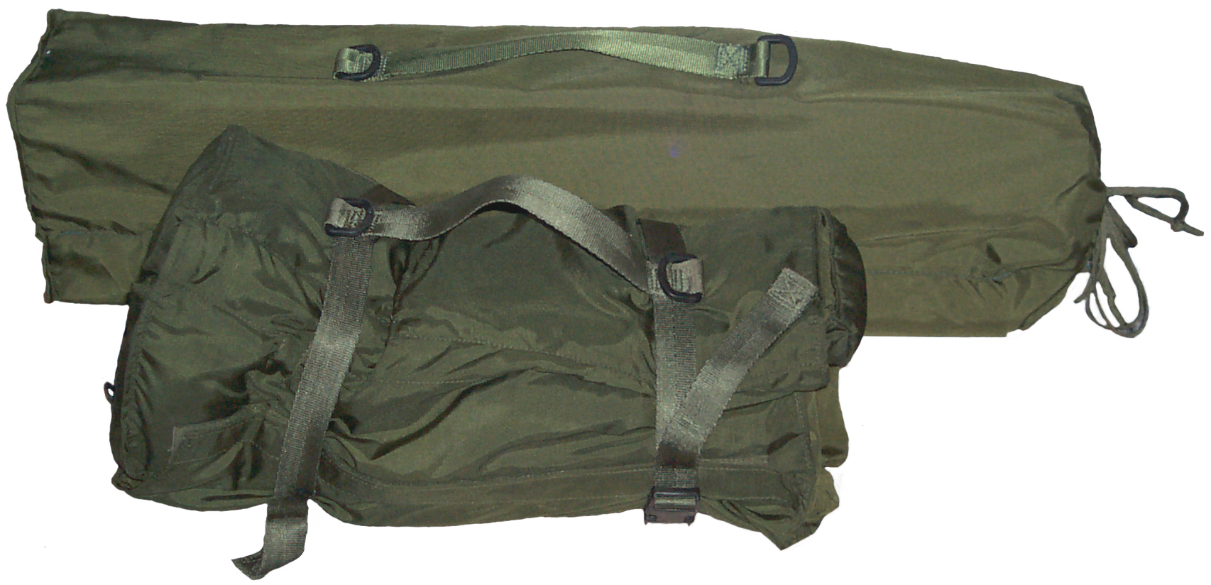
| Radio |
Frequency (MHz) |
| PRC-70 | 2 - 75.975 |
| PRC-74, 74A | 2-11.999 |
| PRC-74B, -74C |
2-17.999 |
| PRC-77 | 30.00 to 75.95 |
| PRC-104() | 2 - 29.999 |
| PRC-119 SINCGARS | 30 to 87.975 |
| PRC-132 | 1.60 - 49.99 |
There are beads crimped to the antenna wire so that you can
stop at the desired lengths. Instead of using three
different bead configurations they depend on knowing which beads
have already been passed.
| Beads |
Length |
| stop at first bead |
117' |
| pass one bead stop at 2 beads |
175' |
| pass one bead pass two beads stop at one bead |
234' |
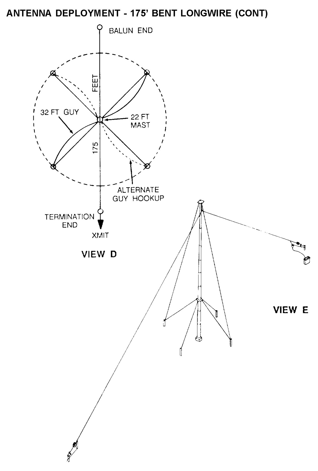
175 Foot Bent Longwire, 234' total
|
In this configuration the near end of the
antenna wire is connected to the radio using the BALUN and
the far end is terminated with 430 Ohms. This
configuration is primarily intended for use in the VHF low
band, very much like the OE-303. |
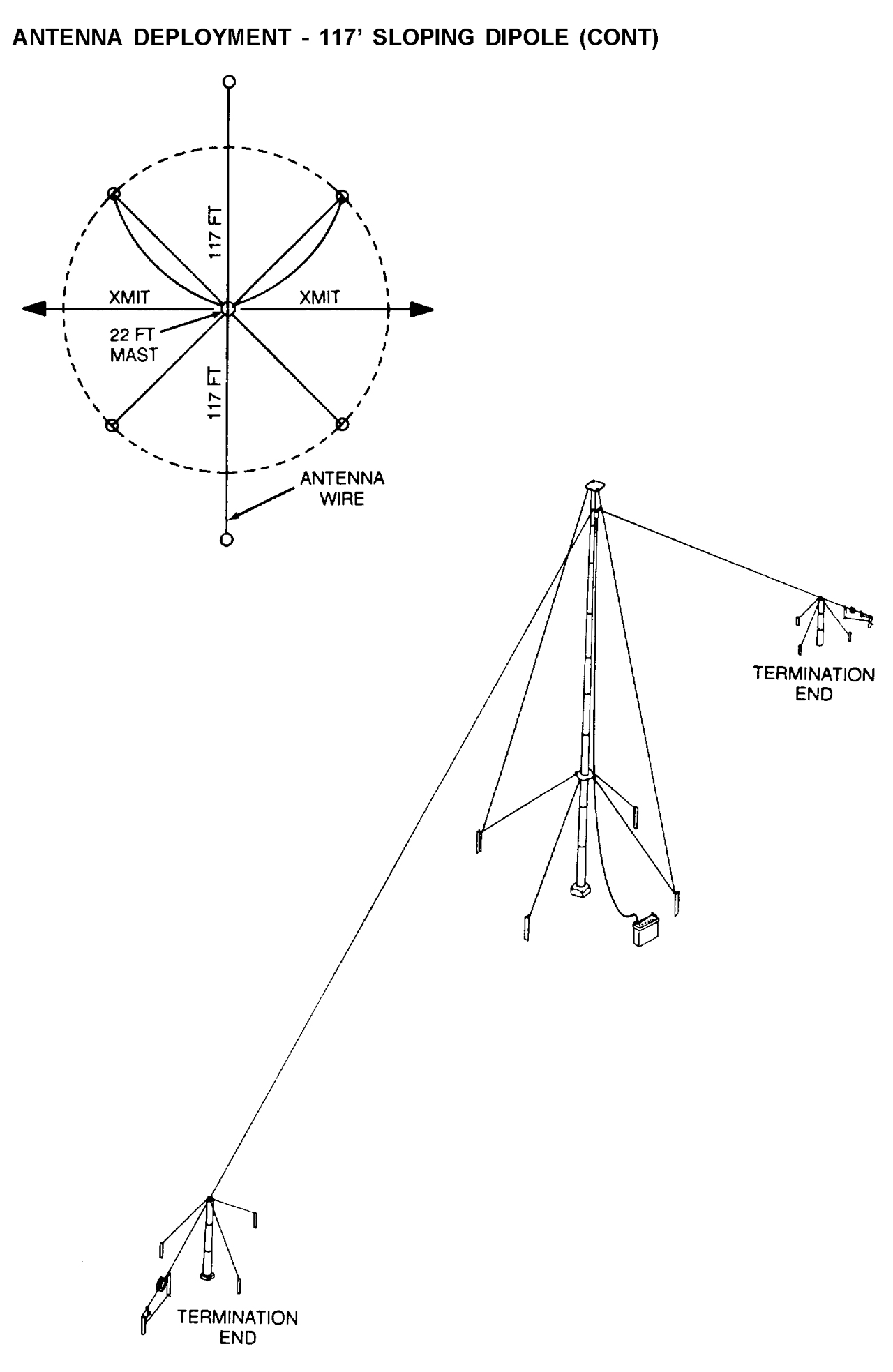
117 Foot Sloping Dipole 234' total
|
This would almost be called an inverted "V"
in ham radio literature. I say "almost" because in
this case the antenna is not resonate and the wire ends
are terminated, whereas for a ham radio antenna the ends
would be left open. Note that the common formula for
calculating a wire dipole is total length (ft.) = 468 /
Freq (MHz). Using this formula you would calculate
that for 2 MHz the length should be 234 feet. Since
the wire ends are terminated the length is not really
critical except that it needs to be greater or equal to a
half wavelength at the frequency of operation in order to
get useful radiation. At the lower H.F. frequencies the antenna height for 1/4 wave varies from 123' at 2 MHz to 8 feet at 30 MHz. So for the low H.F. frequencies that antenna is close to the ground and operating in the NVIS (Near Vertical Incidence Skywave) mode where the signal is sent almost straight up. This is similar to the AS-2259 except the SORAK mast is much taller and the wires are much longer so it should work much better than the AS-2259. In the 2 to 10 MHz range there's good radiation straight up, good for NVIS operation. Note the diagram in the manual says that the gain at 2 MHz is about -14 dB and at 10 MHz about -10 dB numbers not uncommon for NVIS work. |
117 Foot Sloping Vee
|
The plan view of this antenna looks like a
standard rhombic that has had the two far legs removed and
the terminations added to the existing legs.
Intended for use in the 4 to 12 MHz frequency range. It looks like when they made the manual the figure for the 234' Sloping Vee was cut and pasted into this section, i.s. both figures look the same. I think this one should show a wire length of 117' instead of the 234' shown. So there's come confusion between the two versions of a sloping Vee (hald rhombic). |
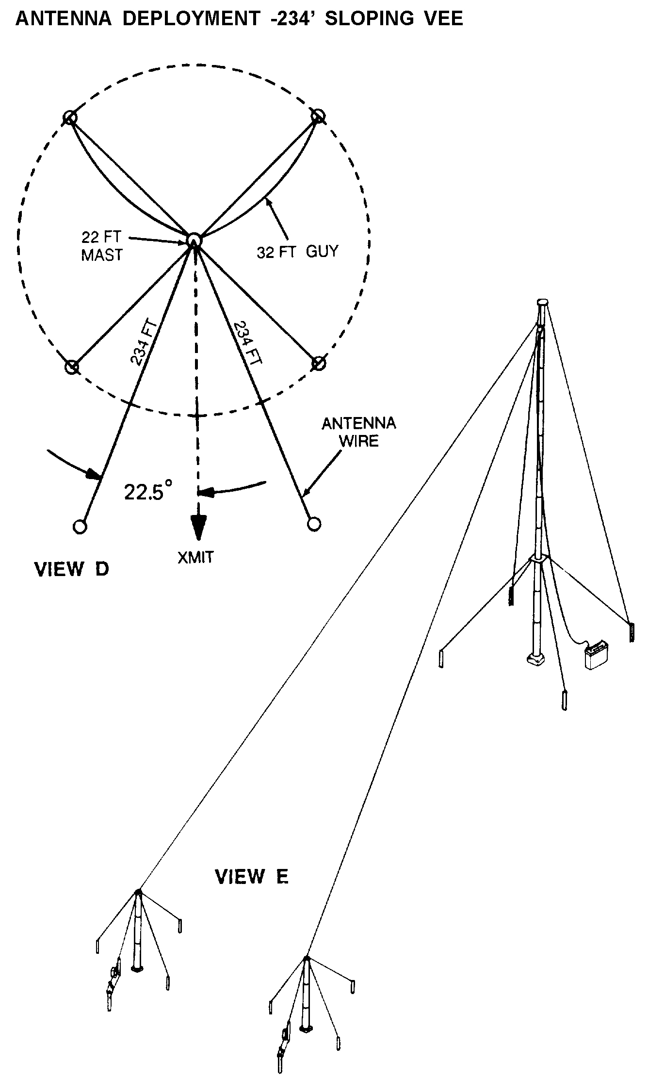
234 Foot Sloping Vee
|
The plan view of this antenna looks like a standard rhombic that has had the two far legs removed and the terminations added to the existing legs. Intended for use in the 8 to 24 MHz frequency range. Single bead on antenna wire. |
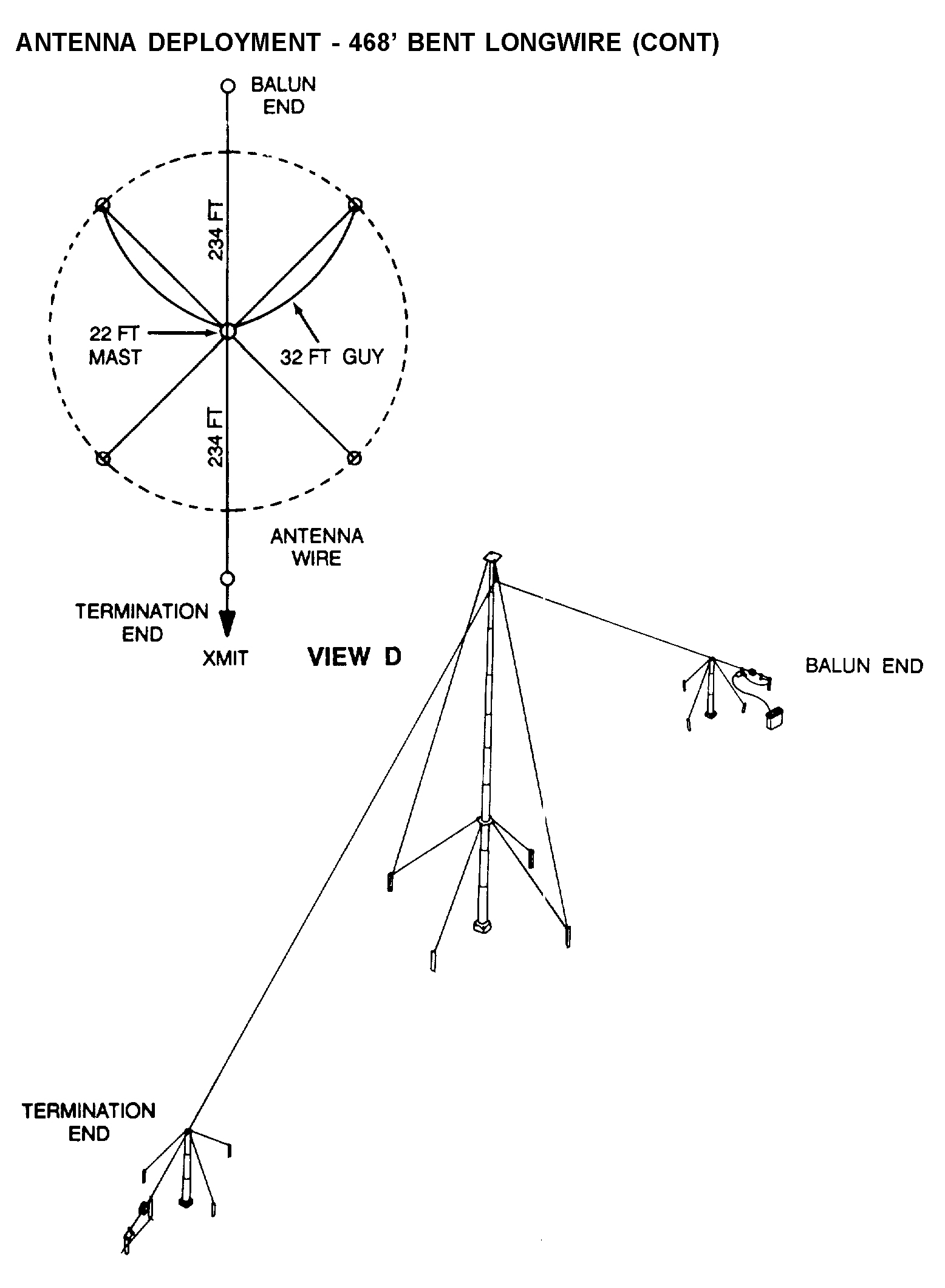
468 Foot Bent Longwire
|
This is what's more commonly called a Half
Rhombic similar to the OE-303,
but in this case made longer to work in the HF frequency
range. The radio is connected to one end that's
supported on a 6' mast using a 6' coax, the 22' mast is
holding up the center and a termination is connected to
the far end also supported by a 6' mast. This
configuration should provide the longest range (1500 to
2500 miles) operation over the 2 to 20 MHz range.
It's a directional antenna with the main lobe radiating
off the antenna toward the termination. In the 8 to 20 MHz H.F. frequency range the pattern is in the 10 to 20 degree elevation range, but at 30 MHz there are many many lobes in the 50 to 90 degree range where they are of no value. The peak gain may be as high as 8 dB. |
Wire Length
There are two antenna wire reels and each of them can be unrolled to three lengths: 117', 175' or 234' if only the existing beads are going to be used.
There are always two legs because of guy tension and/or electrical symmetry.
But there's no requirement of equal lengths, so each leg can be either 117', 175' or 234' independently of the length of the other leg. This might improve the match and or pattern for some frequencies
Plan Arrangement
There are two physical arrangements of the antenna legs. They are either in a straight line or in a Vee. The straight line antennas are called dipoles, or long wires and the others "Vee".
Connections
Stock Balun & 2 Terminations
There are always three electrical nodes: two terminations and one feed balun. The blaun can be installed either at an end or at the center.
It may not make sense to feed a "Vee" from an end even though it's possible and might make for a interesting experiment.
Dipole (Balun & 2 wires)
This would require setting the length of the antenna wires to make a resonate dipole antenna. This can be done using the supplied white noise bridge and knowing the equation: dipole end to end length in feet = 468 / frequency in MHz. to estimate the length and then pacing this off on the ground to make a first try. Then erecting the dipole and checking with the noise bridge. The percent error in resonate frequency and be used as a percent correction to the length to tune the antenna.
Loop (Balun & no terminations)
A new connection type would be to connect the two antenna wires together and connect the balun to the other two wire ends forming a loop.
An example of that would be to install the balun at the top of the 22' mast, run each wire down to a 6' mast and then run the wire along the ground and join the two ends at the base of the 22' mast.
Maximum length inverted delta loop with top feedDipole
22' mast - 6' mast = 16' triangle height, from the Pythagorean theorem (Wiki)
let D = length of horizontal wire on ground from 22' mast to 6' mast.
then the length of the wire from the ground to the top of the 6' mast is 6;, then to top of 22' mast is 234'-6'-D or 228-D
[228-D)^2] = [51984 - 456D + D*D] = 16^2 + D^2 = 256 + D*D, or 51984 - 456*D = 256, or 51728 = 456*D, D=113.4'
sloping wire = 234 - 6 - 113.4 = 114.6'
This is not an option because there's is no dipole center connection method supplied in the SORAK kit of parts. But it could be easily added from the GRA-50. Adding the frequency calibrated tape measure from the GRA-50 would allow the SORAK to work like a GRA-50.
Permutations & Combinations
All of the antenna configurations above could be modified by changing the wire length. That also might improve the pattern/gain/match for some frequencies.
One example the 234' inverted V that now works down to 2 Mhz could be extended to 1 MHz by making each leg 234' long (468' total).
TS-4350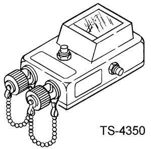 |
The TS-4350 is a power meter that is used with a transmitter to measure forward and reverse power allowing determination of VSWR. This is very similar to the PRM-34 Test Set or better the URM-182A TS-3754/U VHF Low Band Power Meter "...it is marked 2-88MHZ, it has a internal load feature, forward and reflected power setting and will read 0 to 50 watts". K1HF |
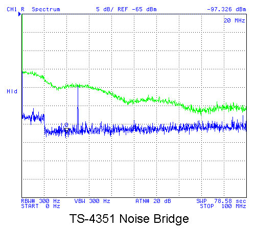
TS-4351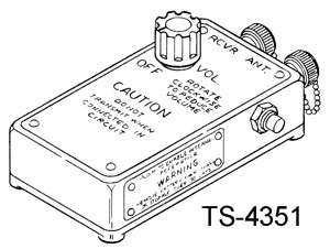 |
TS-4351 is a noise bridge that can be used to check antenna VSWR at the frequency set on the receiver |
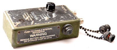 Off turns off the internal 9 volt battery. Pressing button on side turns off noise. Probably usable for HF and VHF low band. I got this one from Mike Murphy. |
 |
| Plomar Engineers
used to make a "R-X Noise Bridge" that covers 1 to 100
MHz, but it's now obsolete. manual
+ added info at Bama, they show up on eBay. Wiki "Antanna Analyzer" is about the noise bridge. |
Googling for "Antenna Noise
Bridge" will bring up ready made units and kits. Far Circuits has the PCB for the QST Dec 1987 Noise Bridge for under $10. AEA - Autek Research MFJ Enterprises Palstar New Jersey QRP Club - Rainbow Antenna Analyzer |
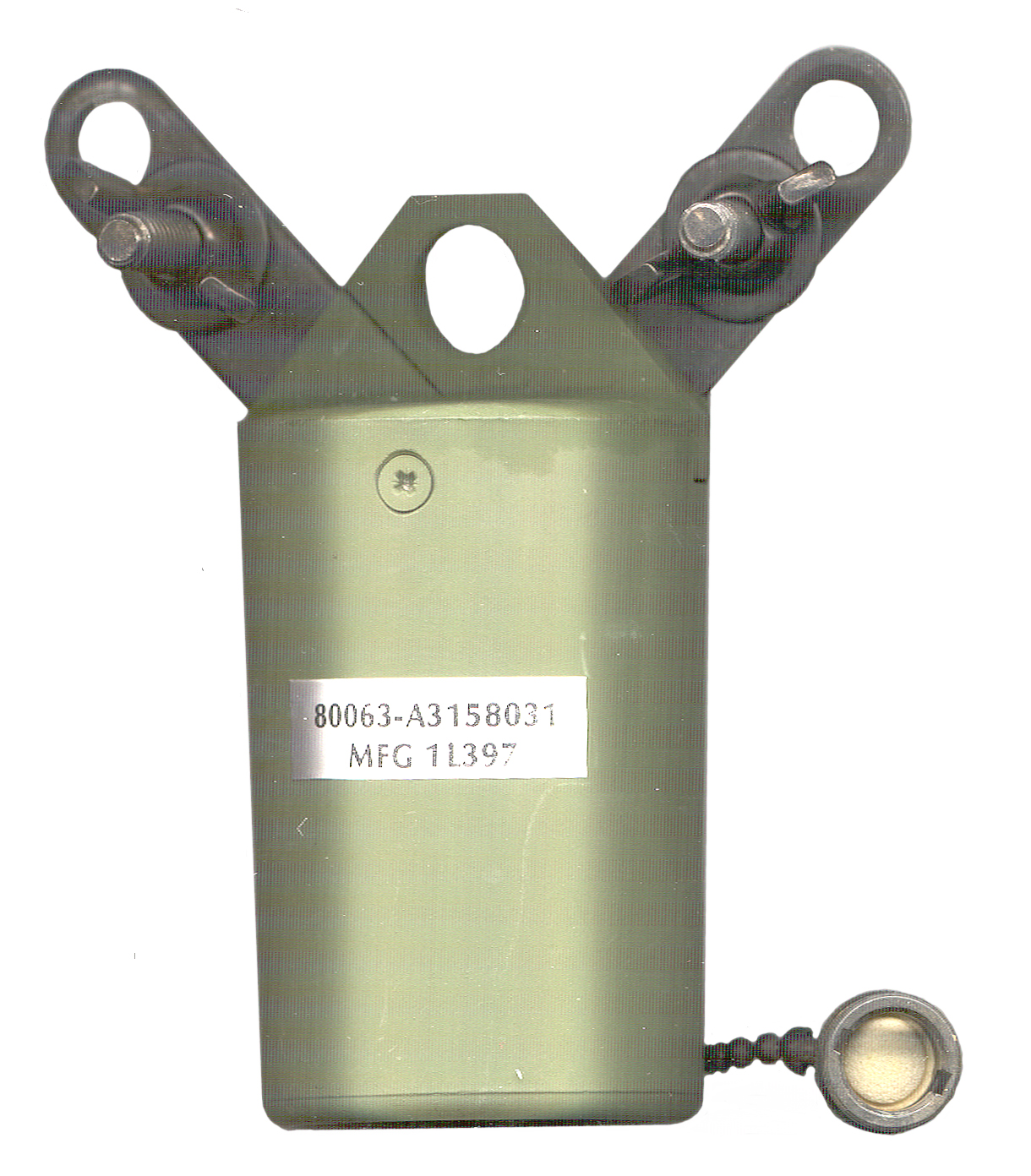 BALUNTermination
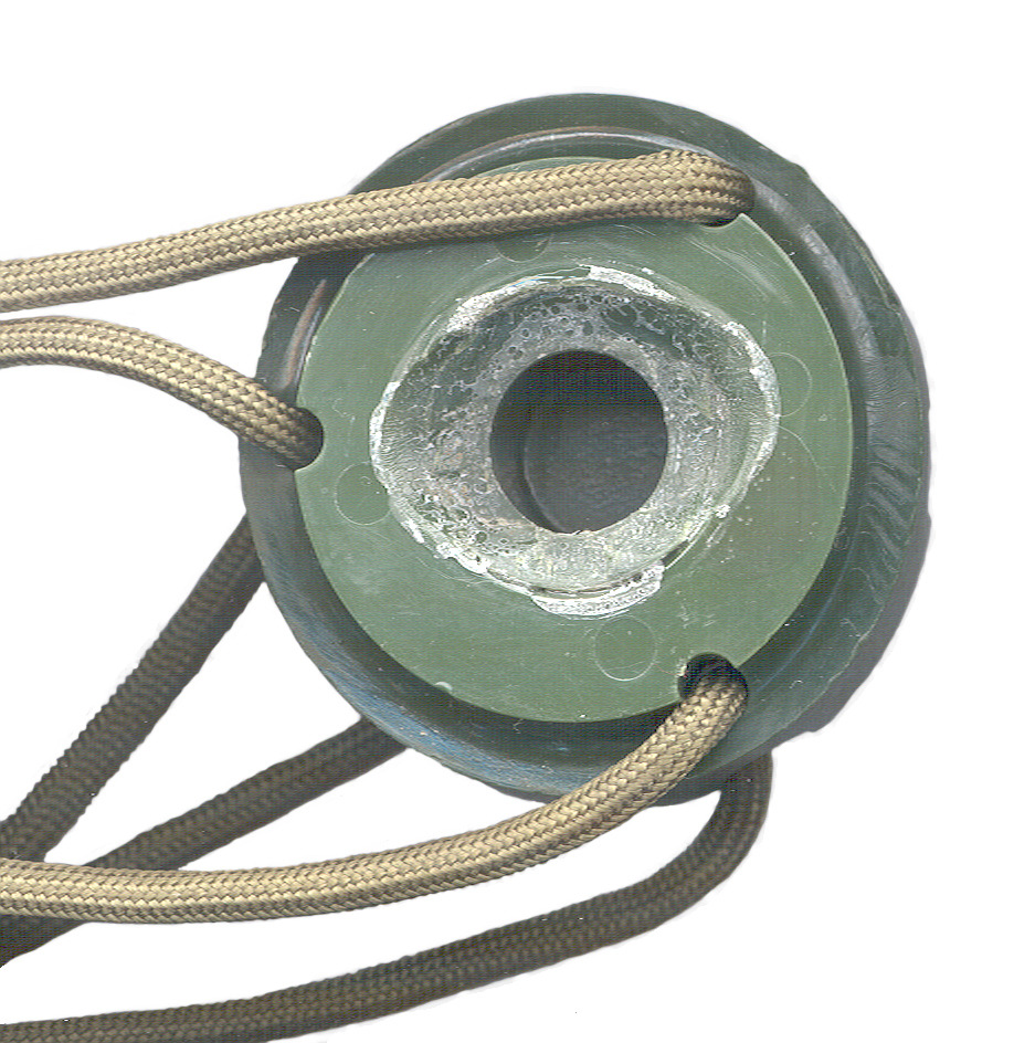 One
of the 6 foot masts has had it's cap decapitated. I
don't know when this happened, but suspect that it was caused by
the heavy 22 foot mast banging against the shaft part of the 6'
mast while the 6' mast cap was on the ground or floor.
Putting the light weight 6' masts right next to the heavy 22' mast
in the same carry bag doesn't look like a good thing to to.
One
of the 6 foot masts has had it's cap decapitated. I
don't know when this happened, but suspect that it was caused by
the heavy 22 foot mast banging against the shaft part of the 6'
mast while the 6' mast cap was on the ground or floor.
Putting the light weight 6' masts right next to the heavy 22' mast
in the same carry bag doesn't look like a good thing to to.
[an error occurred while processing this directive] page created 13 Jan 2005.