Background
Model Numbers
Description
Gearing
Escapement
Worn Pallets
Worn bushing
Missing Items
Seconds Hand
Coil Winding Vibratory Motor
Winding
Mechanism
Main Spring
Battery Power
Spring Winding Cam
Synchronizing Coil
Laminated Core
Laminated Core Electrical Steel
Sync Coil Data
Strange Armature Material
Sync Relay
Sync Button
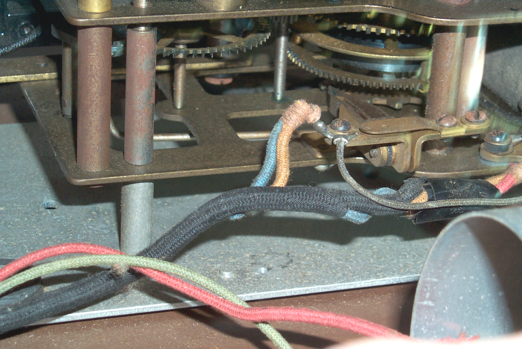
Sync Wiring
Idea for Synchronizing
Radio Time Signals
Electro-magnets & Shunt Resistors
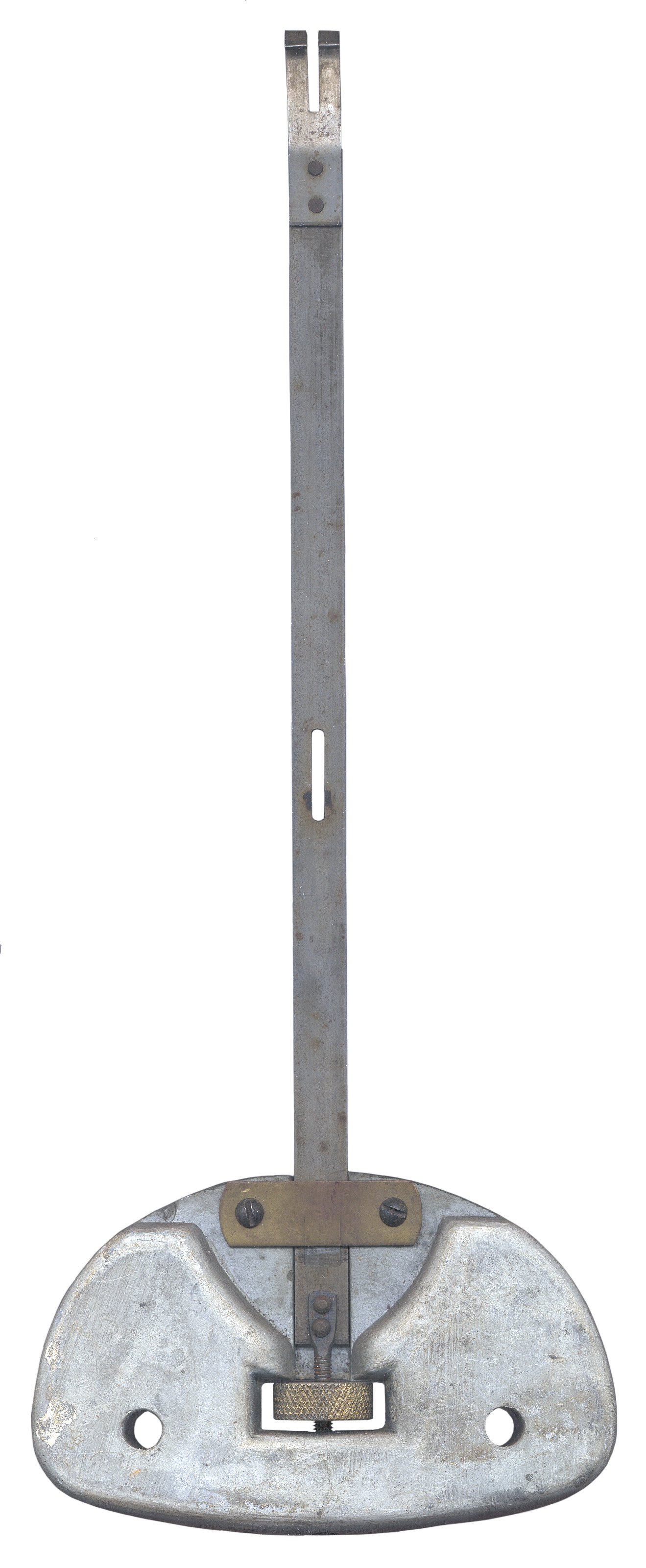
Pendulum
Suspension Spring
Round Case
Cleaning
Burnishing
Lubrication
Assembly
Mainspring Barrel
Drawings
No. 6 Battery Adapter
Questionable Packing
Really Bad Packaging by mickiecat1
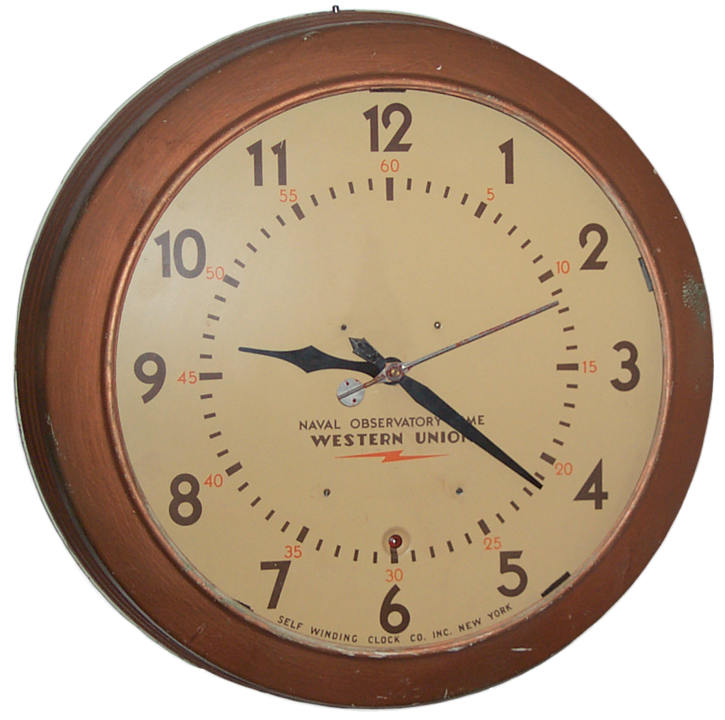
Black Western Union,
Naval Observatory Time
Links
Background
The
first
"Western Union" clock I got only had minute and hour hands
and I wanted one with a big second hand. See that page for most
the the info I have on these clocks.
Model Numbers
Model
|
Dial
dia"
|
Dial
dia
|
Shape
|
Pendulum
|
Beat
|
Case
|
Back
|
Dial
ctr
to Mtg scr"
|
25
|
11
|
12
|
|
|
|
Metal
|
Metal |
6
|
25
|
15
|
16
|
|
|
|
Metal |
Metal |
8 5/16 |
27
|
10
|
11
|
|
|
|
Wood
|
Metal |
5
5/8
|
| 27 |
12 |
13
|
|
|
|
Wood |
Metal |
5
5/8 |
28
|
10
|
11
|
|
|
|
Wood |
Metal |
5
5/8 |
| 28 |
12 |
13
|
|
|
|
Wood |
Metal |
5
7/8
|
35
|
10
|
11
|
|
|
|
Wood |
Metal |
5
5/8 |
| 35 |
12 |
13
|
|
|
|
Wood |
Metal |
5
7/8 |
37
|
11
|
12
|
Round
|
|
|
Metal |
Metal |
6 |
| 37 |
15 |
16
|
Round |
|
|
Metal |
Metal |
8 5/16 |
41
|
|
|
|
Mercury
|
60
|
|
|
|
42
|
11
|
12
|
|
|
|
Metal |
Metal |
6 |
43
|
11
|
12
|
|
|
|
Metal |
Metal |
6 |
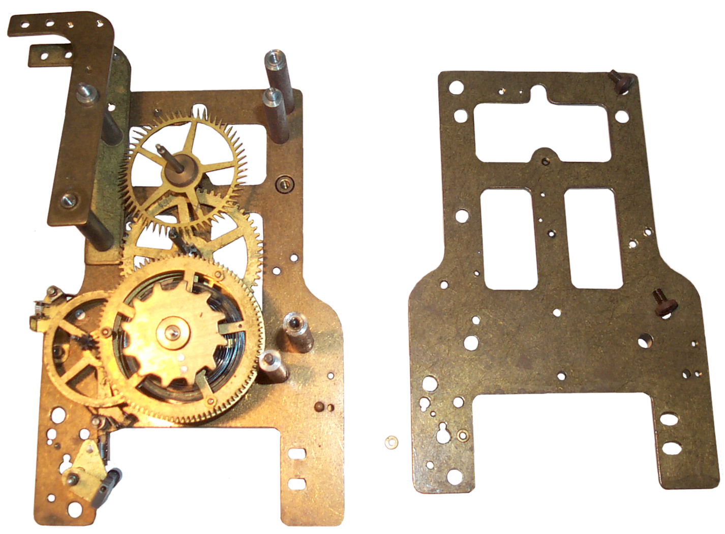
Description
Overall diameter about 19" by under
5" thick. 15" opening in case to view dial.
The dial is 16" in diameter.
Glass missing from case, maybe should be 15.5" OD.
Movement # 402449. Subtracting the number on the other
S.W.C.C. movement yields ( 402,449-39,580) 362,869. It's
very unlikely that by chance I have the first or last of the
Western Union clocks, so an estimate would be that they made over
400,000 thousand clocks between 1934 and 1970. Probably
making most of them in the earlier years.
Henry says that the sweep second had was a request from the
broadcast (radio & TV) business that needed to start their
shows at the exact top of the hour.
Marybeth inputs -
- movement 402449 made early 1930s
- The winder cam has 12 lobes, i.e. every 5 minutes
- model # is 37SS
- although the 15" diameter glass is not readily available
the 15.375" works with some sticky backed Velcro under each
tab
- I'm missing a circlip that holds down the minute hand.
- I'm missing the cover attachment knurled screw.
- This clock has the movement moved lower than clocks
without a second hand so as to place the escapement shaft in
the center of the dial other clocks (of all makers) place
the hour shaft in the center of the dial and add the other
hands around it. This is a very different design that
has all the hands revolving around the seconds shaft
- The movement is still the "F" but has a bunch of
"appendages" to handle all the extra stuff
- The case is probably "Battleship Gray", but I need a way
to figure that out
- When the small knurled nut is removed from the movement it
should be clipped into a large safety pin. That way if
it's dropped your can find it and also it will not roll when
clipped.
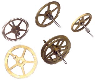
Gearing
The pendulum has a 1/2 half second
beat or 1 second period so the escape wheel (60 T) advances makes
one revolution per minute.
The pinion gear (8T) on the escape wheel advances one tooth each
7.5 seconds.
The first idler shaft gear wheel ( 60 T) takes 60 * 7.5 sec or 450
seconds ( 7.5 minutes) to make a turn.
The pinion gear ( 8 T) on the first idler shaft takes 56.25
seconds for each tooth.
The gear ( 64 T) at the front of the minute shaft is attached to
it's shaft and takes 56.25 s * 64 = 3,600 ( 60 minutes) seconds to
make a turn.
The gear (28 T) on the front of the minute shaft takes 60 min / 28
minutes to move 1 tooth.
The second idler gear (56 T) takes 56 * 60 min / 28 = 120 minutes
to make a turn.
The second idler pinion (12 T) takes 10 minutes for a each
tooth.
The hour gear (72 T) takes 10 min * 72 = 720 minutes (12 hours) to
make one turn.
The second idler gear drives the minutes hand gear (28 T) (not the
minutes shaft) since both the minute shaft gear and the minute
hand gear connect to second gear and both have the same
number of teeth ( 28 T) the minute hand moves at the same rate and
in the same direction as the miunte shaft.
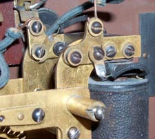
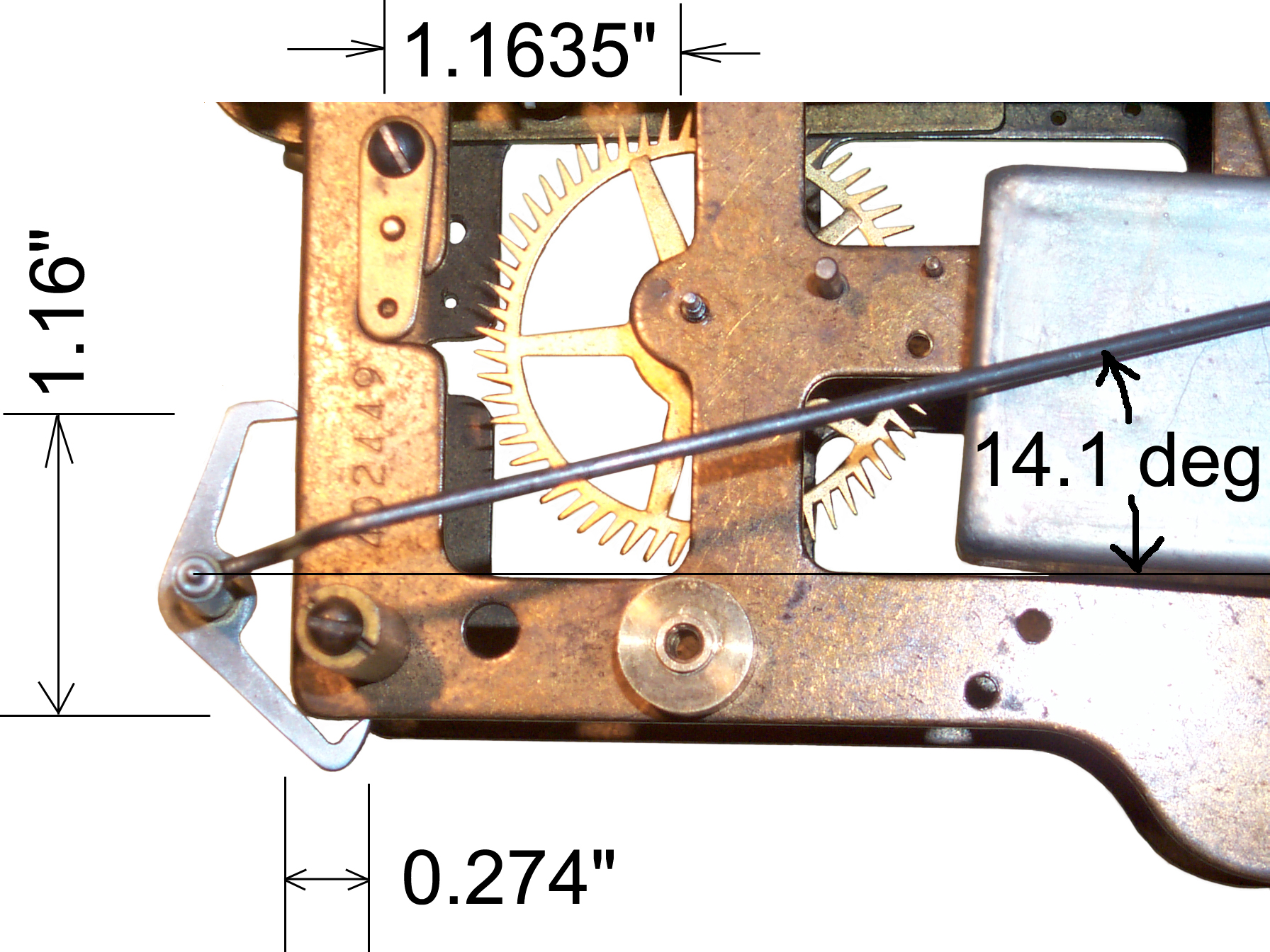
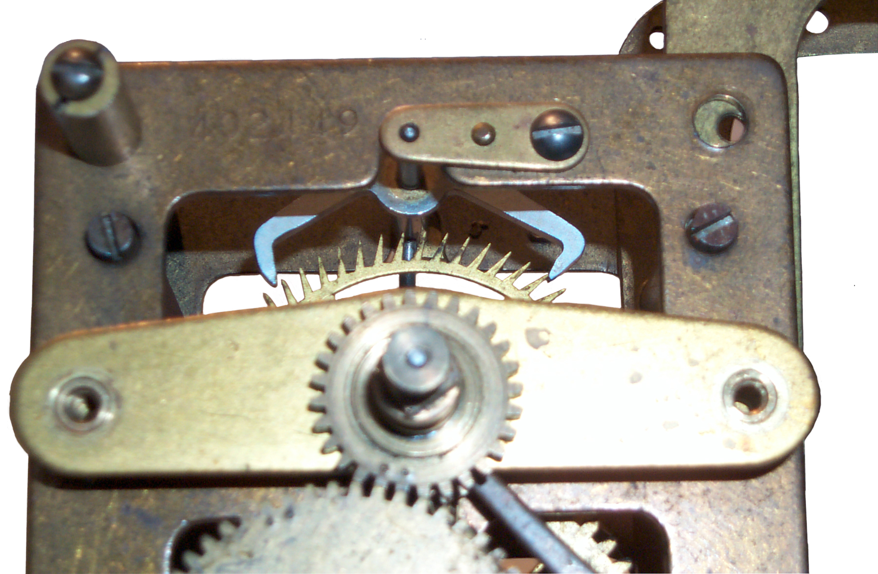
Escapement
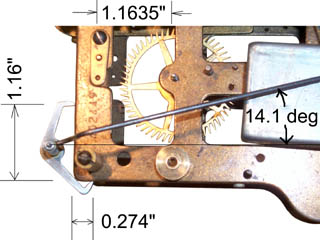
I've
tried a number of ways to measure the anchor, and none of the
prior methods worked for me. But this method of
photographing the anchor held on a corner of the frame and with
the flats of the pallets parallel to the frame seems to give very
good results.
The silver rectangle on the right is used as a spacer to get the
crutch rod at the correct height and it's being pulled to the
frame by rubber bands hooked on the end just to the right of the
photo.
The distance between the pallet faces can be computed as
SQRT(1.16*1.16 +0.274*0.274)=1.192"
The distance between the center of the anchor shaft and the escape
wheel shaft center can be measured a number of ways and they all
are within a few mils of 1.1635"
The interesting thing is the 14.1 degree angle of the crutch
relative to the frame. It was measured on the photo and so
may not be accurate. The arc tangent of .274/1.16 is 13.3
degrees. So the crutch is very close to, if not exactly,
square to a line between the pallet faces.
This is s/n 402419 which is one of the newer clocks fitted with a
single coil synchronizer.
The escape wheel has 60 teeth. The diameter across the
points of the escape wheel is 1.865" and at the root of the teeth
is 1.591". 90 degrees divided by 6 degrees per tooth is 15
degrees for a design that has no drop. This anchor spans 13
teeth leaving 12 degrees for drop.
This anchor has a different outline from the older anchors, like
on
s/n 79006, but the pallet faces
are in the same place.
I've heard that this escapement is different from the standard
escapement where the wheel has 30 teeth. For a 60 tooth
wheel the design is different. So the designs published in
clock books for 30 tooth wheels are not the same.
Worn Pallets

The pallet faces have grooves worn
into them that are very deep to the point of generating some
recoil. The other S.W.C.C. clocls I have do not have this
problem.
This is a dead beat, or Graham escapement, it's just not working
that way now.
The links (called cocks) have a pin that can be removed simply by
pressing on the cock while the pin is on a hard surface.
With the pin out of the cock the anchor can be lowered deeper into
the escapement wheel to see how it works. This will have to
wait since now, 27 Jun 2007, the clock is completely apart and has
been cleaned.
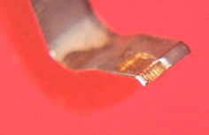
The wear to the back is on the dead face and probably is not too
important, but the wear on the narrow front face has changed the
shape and now causes the escape wheel to turn backwards a little.
Can this be repaired? ans: Yes but not easily.
A better thing to do is move the escape wheel so that it meets the
pallet on the side that is still good. It's almost as if the
factory setup does not center the escape wheel on the pallet but
instead puts it on one side just so that it later can be moved to
double the time until a repair is needed.
Pallet Adjustment
The Graham style anchor is held not by the frame but rather by a
link on both the front and rear frames. The links are
attached by both a screw and a pin to the frame. The hole in
the link that passes the screw is a tight fit. This means
the link is not an adjustment, but rather a way to remove the
anchor - crutch part, like to release the main spring. If
the link screw hole was enlarged then the link could swing about
the pin allowing some up or down adjustment of the anchor.
This might allow balancing the drop on both sides.
The front and rear frame are almost identical stamped parts.
I think the link location was a seperate step that probably was
done using a fixture on each frame plate to set the anchor shaft
hole directly above the escapement wheel shaft the correct
distance. Then the holes for the screw and pin were drilled.
This means that the anchor crutch and escapement wheel are
interchangeable between clocks.
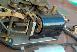
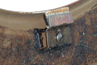
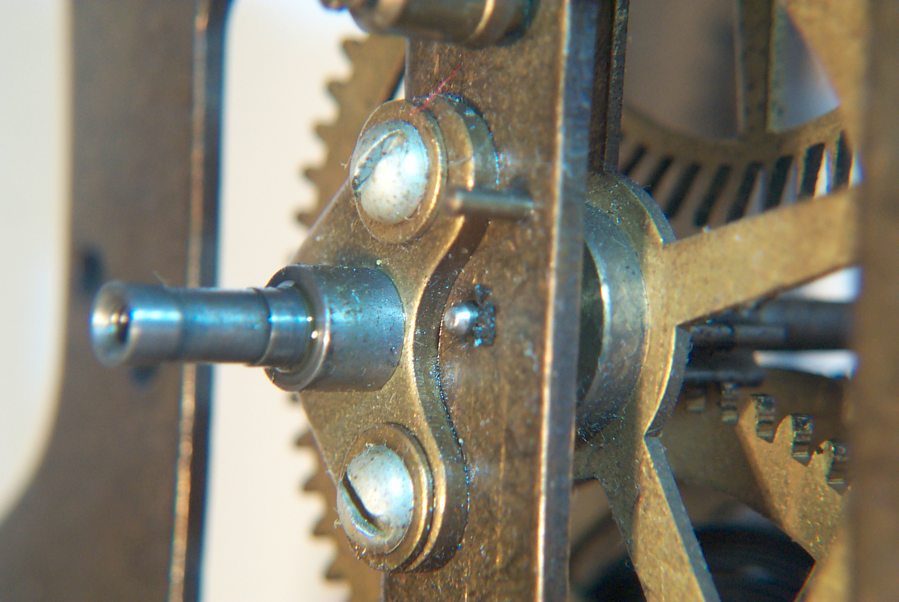
Worn Bushing

The bushing that is driven by the main spring on the front has
black goo around it. That's consistent with the pallets
being worn (see above).
This clock got a lot of use.
The stub shaft probably should not be removed since the holes for
the two screws are oversize to allow adjusting the stub shaft
position. That's why there are flat washers under the screw
heads. This shaft holds an intermediate gear that mates to
similar gears above and below it.
Missing Items
- 15.5" dia front
glass - have received and installed two of them
- Knurled screw to hold front cover onto frame
- FS 172 Minute Hand Clip
- Pendulum support spring and it's two pins
- Vibratiing motor contact roller (black insulating plastic
sleeve) & it's attachment screw. Thre's one on top and
another on the bottom, probably should replace both to be safe.
Seconds Hand
I've seen 4 different ways a second
hand is handled on the Self Winding Clock Co. clocks:
- This clock has a sweep seconds hand (a hand marking seconds
on a timepiece mounted concentrically with the other hands and
read from the same dial as the minute hand). But in this
case the all the hands are mounted on the seconds shaft.
- A regular second hand (a hand marking seconds on a timepiece
not mounted concentrically with the other hands and read from
it's own scale) maybe an inch long located between the dial
center and 12:00 with a hole almost two inches in
diameter. The second hand serves the normal purpose of a
second hand. The hole serves the purpose of allowing
someone to see the contact points of a master clock to confirm
that they are separated from each other, i.e. are not fused
together. If they are fused together all the slave
clocks are stopped.
- A regular second hand maybe an inch long located between the
dial center and 12:00. This second hand is on the 'cape
shaft and is a simple thing to add. The Minute and
Hour hands are on the hour shaft.
- No second hand is also very common. Although the 'cape
shaft is just behind the dial. Virtually all of today's
digital clocks that operate from a quartz crystal do NOT have
a seconds display. That's because they are not accurate
enough.
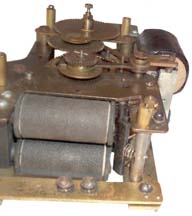
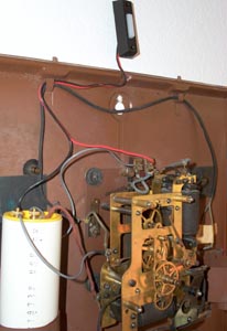
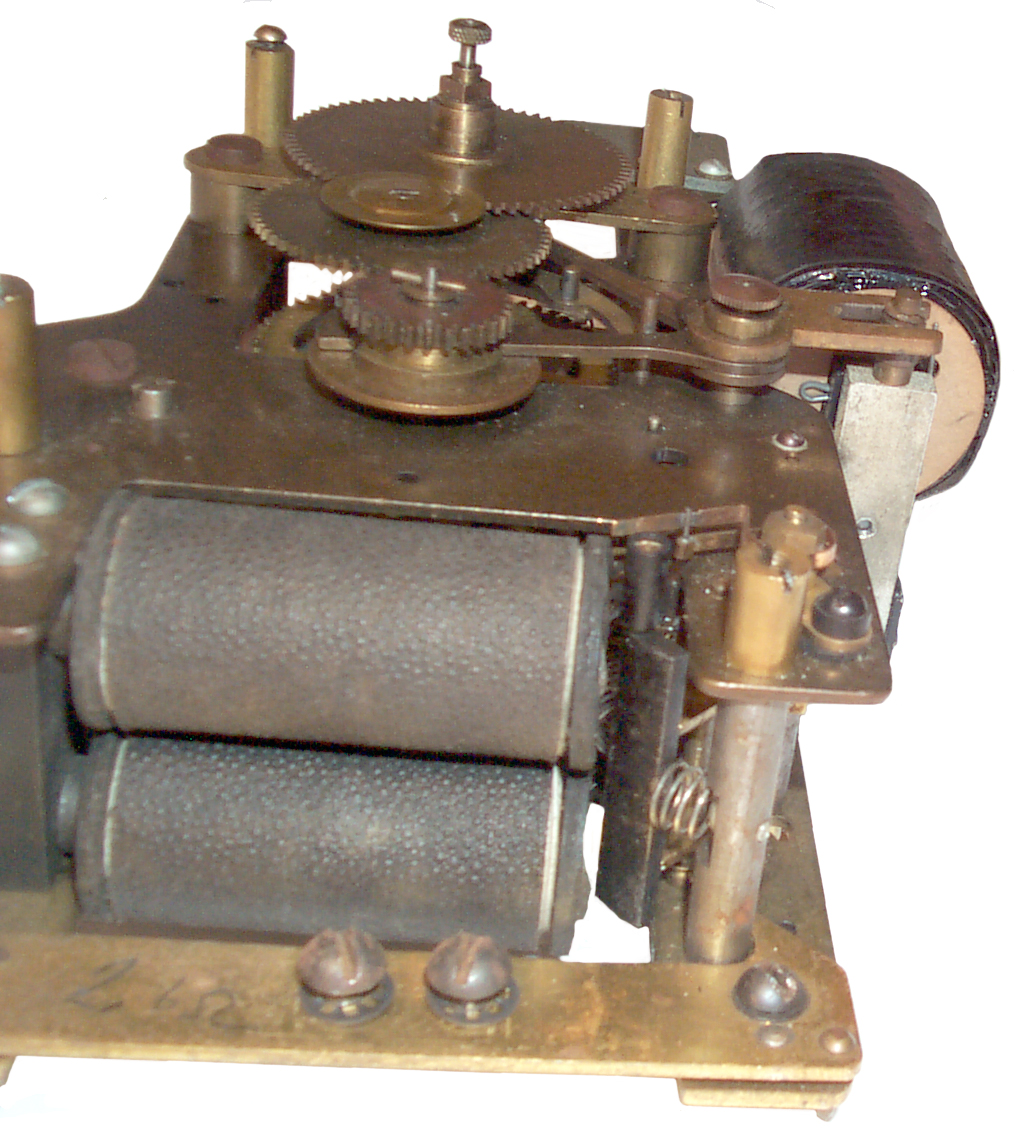
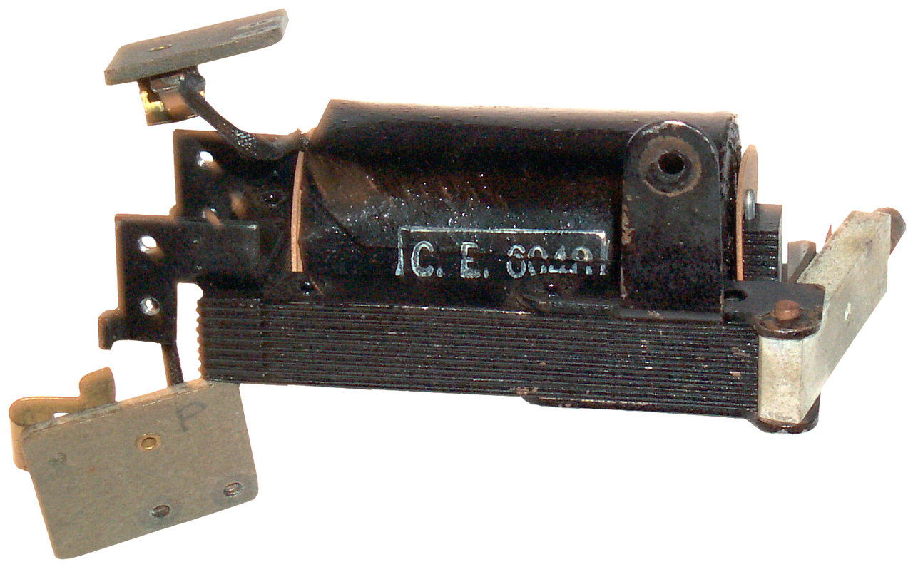
Coil Winding Vibratory Motor
Contacts
on
the
clock close the circuit that connects the local battery to the
winding motor. The motor is the classical two coil type
where each coil is aprox 1" dia x 2" long. About 5 Ohms
resistance. The 4 screws that hold the motor to the frame
were not holding it in the proper place. I changed the
position of the coils so that when the armature is at the top of
it's travel it would just hit the top point of the coil
core. This involves both the left to right and the
rotational position of the coil relative to the clock frame.
This cured the problem of the one coil switch drive pin hitting
the insulating washer on the end of the coil. The other
drive pin is missing. After the coil alignment to motor is
running nicely.
Winding can be manually done while the leaf switch is
pressed. The main spring has an auto stop brake and you will
hear the motor stop winding.
When one of the 12 teeth of the winding cam lifts the leaf switch
and it contacts the other leaf power is sent to the winding
motor. But it's not clear how there leafs are prevented from
shorting to the grounded cam? Also what disconnects the
winding motor from the battery?
Adjustments
9 June 2007
- 4 screws that attch the dual coil assembly to the
frame. Loosen and friction tighten then adjust coils so
that bottom of armature just touches the top of coil cores at
top of swing when upper spring has been removed. I could
not do that on this movement because the insulating cylinder
that opens the electrical circuit hits the coil insulating
washer. So for not set coil bace a little.
Probably should grind off some of the washer so it clears the
contact sleeve.
- Top spring can be rotated by loosening screws on front and
back frame that hold it's support shaft. Top of armature
should just touch spring when it's 1/16" below top of core.
- Bottom spring should just tough armature when top of
armature is even with bottom of core. Again the support
shaft can be rotated to adjust.
- The contacts should be open 1/32" when the armature just
touches the top spring and should sit in the center of the
contact metal when at rest.
- The front are rear springs should "make" and "break" at very
close to the same place. (I'm missing the small screw and
plastic sleeve so can not tune both.
The idea is that when not powered the armature rests on the lower
spring and the contacts are closed. When the circuit is
closed the armature swings up and opens the circuit just as it
touches the top spring but inertia will carry it a little
further. Then the spring throws it back down and about when
it's free of the top spring the electromagnet is energized and
starts pulling it back up.
I found that setting up the motor based on the dimensions is a
good starting point, but it's running weaker than it could
be. So I tried various adjustments while the motor was
running and find that the top spring adjustment is best "tweaked"
while the motor is running and the movement is in a upright
position. The latter is very important since gravity pulls
the armature down. When the top spring is way too high or
removed the motor will run but it's weak. As the top spring
is lowered the motor speeds up and sounds stronger. Too low
and it stops. Once the top spring is set the motor will run
with the movement upside down.
This is sort of like dyno tuning a car compared to doing it by
setting things statically. Dyno tuning results in more power.
The lower spring does not seem to do much. Maybe it needs to
be longer or shorter, not sure. If you could get an increase
in power like the top spring provided then that would really be
something. Door bells and buzzers have the armature
supported on a leaf spring that acts in both directions and they
can be installed in any orientation relative to gravity.
Electrical
When a couple of "D" cells power the coil pair and then the
current is stopped, the kickback is about 40 Volts. The
shunt resistor is marked blue gray black silver which translates
into 68 Ohms 10% tolerance. 40v/68 ohms is 588 ma. An
ohm meter across the combined coil and resistor reads 5.6
Ohms. With a voltage across the coil of 2.5 volts the
current is about 446 ma. The acutual cycle is for no current
to be drawn from the battery between windings which may be 5
minutes or 60 minutes minus say 15 seconds of wind time.
During winding on the up stroke while the contacts are closed the
current tops out around 600 ma. then as soon as the contacts open
the current does not change because the coil generates a 40 volt
spike
It takes 824 us for the 33 volt pulse to recover to 37%.
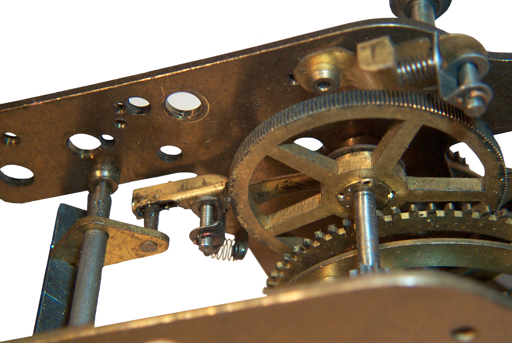
Winding Mechanism

At the left is the armature. When the
electromagnet is activated it's shaft rotates CCW lifting the arm
that piviots about the ratchet wheel. The pawl on the pivot
arm turns the ratchet wheel clockwise. When the
electromagnet is deactivated the armature shaft rotates CW,
lowering the pivot arm. Now the pawl in the upper right of
the photo holds the ratchet wheel and the pawl on the pivot arm
moves with respect to the ratchet wheel.
The ratchet wheel shaft drives a pinion gear, a part of which is
just visible in the photo, which in turn turns the main spring
housing, the rear part being the smooth wheel in the photo.
But the large gear behind the main spring housing is not turned by
the ratchet wheel. The large gear is on the hours shaft.
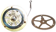
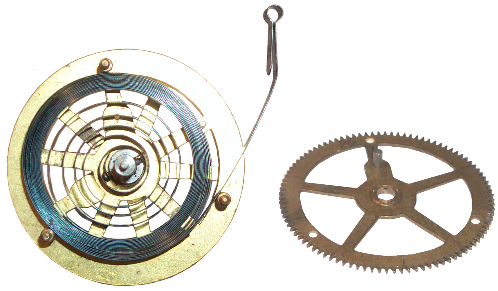
Mainspring Shaft
This minutes shaft is the lowest
one in the clock. The front drive gear is fixed to the
mainspring barrel and drives the idler shaft pinion above
it. The mainspring barrel that consists of the front
spring wheel with a smooth radial surface, the main spring and
the rear wheel that has the winding teeth on it's outer rim is
free to turn on the shaft. The winding cam is also free to
turn on this shaft. The outer end of the mainspring is
attached to a pin between the two barrel wheels. The inner
end of the mainspring is connected to the shaft. There is
a dual ratchet on the fine tooth gear that's driven by the
vibrating motor that does not let the mainspring unwind.
As the clock runs the shaft turns clockwise unwinding the
spring. When the winding motor runs it turns the barrel
clockwise winding the spring.
The cam revolves around the
mainspring (minutes) shaft but is not fixed to the shaft.
It has two pins fixedly attached and pointing to the front of
the clock both positioned on the same radial line. A
radial pin through the mainspring shaft, like a spoke on a
wheel, drives the inner pin of the cam as the clock runs turning
the cam clockwise.
When one of the cam lobes lifts the switch contacts and closes
the circuit the vibratory motor starts winding the mainspring
barrel by turning it clockwise. Note the mainspring barrel
is not fixed to the mainspring shaft, but is free to
revolve.
Starting from completely unwound. The winding motor starts
turning the barrel clockwise. After just under one turn
the the pin sticking back from the barrel picks up the outer pin
sticking forward on the cam and starts to turn the cam.
After about 1/12 of a turn the cam turns off the winding
motor. If at this point the manual switch is activated the
barrel continues to rotate clockwise. After just under one
more turn the the inner cam pin facing towards the front hits
the radial pin fixed to the shaft and this positively stops any
further winding of the mainspring.
So the manual button should not be held down after the motor
stops. I expect the design of the winding cam is such that
the internal switch is open after the mainspring is wound to the
stop.
By making the ratchet teeth very fine on the winding ratchet gear
the amount of dead space is minimized making for a more efficient
winding mechanism.
These videos were made prior to disassembly.
SWCC2AlmostWinding.avi
- but stops - as clock was received
SWCC2Winding.avi - after
adjusting the motor
SWCC2WndMech.avi - frame like
shown in winding mechanism photo above, armature moved manually
Main Spring
Strength
It looks like the torque on the
escapement wheel when the spring is just about to run out is
around 3.9 grams * 2.2 cm (8.6 g-cm). When the main spring is
wound to the fixed stop the torque is about 5.6 g * 2.2 cm (12.3
g-cm)..
Removing Tension
The anchor is held in place by adjustable bars on the front and
back frames. By removing the bar on the rear frame the anchor and
attached pendulum drive crutch can be moved free of the 'cape
wheel and by light finger pressure you can control the speed of
the wheel to allow the spring to unwind.
Battery Power
Spring Winding Cam

A cam located
on the hour shaft activates a leaf switch that turns on the
winding motor about every 6 minutes. The manual winding
switch (near wires) is connected in parallel with the leaf switch
activated by the cam. Note that by winding more frequently
the tension of the spring on the 'cape wheel will be more uniform
and because of that the clock should keep better time.
This is very different from the single lobe cam used in the prior
Self Winding Clocks that should only wind once per hour.
At the left of the photo you can see the 'cape wheel (seconds
shaft) and the rod used to drive the pendulum is visible below the
back plate.
The silver shaft in the center is the minutes and the spring is on
the hours shaft to the right.
Synchronizing Coil
 Laminated Core
My guess is that the laminated core was the key technology needed
for a single coil to replace the dual coil setup that was used
since about 1840. Since the "Western Union" clocks started
around 1934 and ended about 197? the laminated core coil may
be a fairly new development.
For comparison look at the
Sync
coils on an earlier Self Winding Clock.
Marked in white paint box:
(C.E. 0088?)
This is the first time I've
seen a single coil in this application. All the others have
been dual coils. The single coil has a larger diameter
(1 11/16" dia x 2 1/2" long) and the most important feature
is that it uses a laminated stack of metal to form the return
magnetic path. All the dual coil setups are using single
chunks of soft iron for the magnetic path. The problem with
a single chunk of metal is that when the magnetic field changes
Eddy currents cause losses which get fixed when laminations are
used.
Note when A.C. mains power became available Eddy currents quickly
became understood. But in the days when DC was the only kind
of electricity that was being used no one saw the need for
laminations. But you would notice that the efficiency of an
electromagnet would suffer when there was any kind of a magnetic
path outside of a coil. Note that in all these electromagnet
applications the E-M does not just sit there doing nothing.
The only time it has value is when it's pulsed, i.e. turned
on and off. During the changes is where the need for the
laminated core comes into play.
In Charles R. Underhill' book "Solenoids, Electromagnets and
Electromagnetic Windings" first edition 1910 second edition 1914.
Laminated cores are mentioned in relation to AC plunger solenoids,
and nowhere else. There are many mentions of "Iron clad"
solenoids and electromagnets, but never laminated ones.
Laminated Core Electrical Steel (Wiki)

In
October
of
1890 Steinmetz was asked to calculate the loss in iron motor
cores. By 1892 he was publishing papers on the loss.
He said the hardness, saturation and hysteresis are the three
properties of the core material. (Ref Science Vol. XX No. 509,
1892)
Allegheny Technologies -
Electrical
Silicon
Steel
- Grain Oriented Silicon Steels - when the DC is turned off
these have lower remanent magnetization than soft iron
cores. They also have higher saturation magnetization thus
can be smaller or use less current.
The laminations are about 0.030" thick. At the left of the
photo you can see that there's a small end gap between two
different laminations on the same layer. There is a similar
gap at the left face of the coil. So to get this "U" shape
core the laminations are "L" and "I" shapes.
The central core is 0.533" x 0.420" for an area of 0.224 sq in.
(144 sq mm).
Sync Coil Data
The wire is enameled about 0.029" dia, or maybe AWG 22 wire.
6 Ohms would take (
Cooner
Wire) 6/16.2 = 370 feet.
The coil might have an ID of 0.68" and OD of 1.6" with a length of
2.3" this gives a rectangle for the turns that's 0.46" high
x 2.3" long or 1.058 sq inches. If each wire was a square
0.03" on a side then 1,175 turns would fit. The mean radius
is 0.522, mean circumference is 3.27" which times the number of
turns is 3,850" or 320 feet, not too far from the computed 370
feet.
Wedging the armature in the open position and using the
FLC-100 magnatometer to measure
the filed at the end of the core while the coil current is varied
from 0 to 250 ma produces the following
plot. The coil is clearly
saturated at 250 ma.
Marked in white paint box:
(C.E. 0088?)
1873659 Process of Treating Silicon Steel, August 23, 1932,
148/110 ; 148/111; 29/17.2 - aka Magnetic steel
1714038 Process of Treating Silicon Steel, May 21, 1929, 148/110
Tool steels are made with the minimum possible amount of silicon,
very different from magnetic core silicon steel.
So have not found a patent to cover this. But I was looking
in the 1890 to 1940 time frame, but now think it's in the 1934 to
1970 time frame.
6 Ohm sync coil at 3 volts draws about 450 ma for a pair of
"D" cell batteries. Does actuate but hard to say if enough
force to move hands far.
11 June 2007 - Sync coil testing - The coil measures 150
Ohms and 135 mH using the
HP 4332
LCR meter. This is an AC measurement, not DC. These numbers
are probably bad since the coil is 6 Ohms DC.
Tried remeasuring the DC resistance with a Fluke 87 DMM and get
wildly varying readings. The AC volts output from the sync
coil jumps around hundreds of mv if the armature is wiggled.
The proper drive is going to be a voltage much higher than 3 volts
from an even still higher voltage loop with current
limiting.
Based on the DC power supply the coil resistance is 5.9
Ohms. Armature just pulls in at 0.71 V @ 0.105 A.
Reasonable sounding action at 3 volts, movement standing up,
either polarity.
11 July 2007 -
2.5 volts across the coil gives current of 417 ma. With a
327 ohm resistor across the coil the kickback voltage is about 100
v.
.417 A * 327 Ohms = 136 Volts just after the instant of turn
off. After 125 us it has recovered to 100 volts. The
time to recover to 50.5 volts (37% of total change) is the time
constant, and is 710 us. If this is just an L/R time
constant then the self inductance is about 232 uH. I doubt
this is the case.
If we take 3 time constants as the time to settle, i.e. 2.13 ms
then:
V = L * dI / dT, so L = V * dT / dI = 136 v * 2.13E-3 / .417 =
0.694 H or 694 mH
Using a 1k resistor across the coil the instantaneous kickback
voltage will be 417 volts. 37% is 154 V.
272 us is the time constant. If L/r then L is 88.9 mH.
Using Self Inductance:
L = 417 v * 3 * 272 us / .417A = 816 mH
A method of testing is to put the HP 54501 scope in triggered
single shot mode. Connect the two batteries to the
synchronizer coil. Then clear the scope display (which arms
the trigger) and quickly disconnect the clip lead from the coil
terminal. This generates the negative spike cleanly.
With a 10X probe the max volts/div is 50 * 8 divisions is a max on
screen range of 400 volts. The one shot bandwidth is not
that great on this scope.
It's not clear what the value of self inductance actually is.
Placing a diode across the coil slowes down the recovery time to a
little more than 157 ms. This is a real bummer.
Heard from Henry that the line voltage was 120 and the current was
250 ma. No more than 25 series connected clocks on one
circuit. The panel has an adjustable resistor to set the
current.
My example:
20 clocks where each has 6 Ohms DC resistance so 120 Ohms clock
resistance. The wire resistance might be 150 Ohms for a 1
mile loop, more for longer loops. So the current would be =
120 Volts / (120 + 150) Ohms or .44 amps. So to get down to
1/4 amp the sending station resistor would be adjusted until the
current was 1/4 amp which would take about 210 Ohms.
Now look at the impact on the charging time constant.
With 120 Volts and 1/4 amp the loop resistance will be 400
Ohms. The mix of clocks, wire and adjustable resistor may
change but that's the total. So now the time constant of any
clock is made faster by 400/6 or 66 times. This is a very
big improvement in the speed of operation. It applies to
both charging the inductor and discharging.
Strange Armature
The armature is constructed from materials I don't recognize.
The side away from the coil looks like aluminum (lead?), but a
magnet sticks to it. On the other side it looks like
asbestos. On the coil side a thin iron strip is attached
with a screw (hole tapped into "aluminum") that has a "V" pointing
to the bottom of the coils central laminated core.
Trapped under the iron strap is a thin sheet of brass that extends
up higher than the core, so when the coil is charged and the
armature closes the brass prevents the asbestos from touching the
central core. But when the coil is installed in a clock that
can't happen because of the connection to the clock mechanism.
Synchronizing Relay
This is a new item that's probably part of the single coil
setup. In the older
Self Winding
Clocks the synchronizing coil was driven from line
power. But in this case there appears to be a classic design
dual coil relay that the line activates and then uses the local
battery to drive the single coil. I haven't traced it out, but
that's what it looks like.
Both the older and newer clocks use the local battery to light the
red "lightening bolt" lamp each time the clock gets
synchronized. When the lamp is dim it's a clue the battery
needs to be replaced. The other clue is the winding takes
longer and sounds different (just a guess).
12.7 Ohm relay coils is the load on the line feeding the clock.
Synchronizing Button
In
Fig 6 above
is shown a Synchronizing Button. It's simply a doorbell
button with one wire going to the battery terminal for +3 volts
and the other wire going to the left Fahnestock Clip. A
short wire goes from the -3 volt battery terminal to the right
Fahnestock Clip. Push at 1 second till the hour brings the
minute and second hands to 12:00 and release at the hour to allow
them to move again.
I tried this with a long wire and it did not work. That's
consistent with what I've been learning about the
No. 6 Dry Cell being capable of delivering
currents in the area of 20 Amps. When I was testing using an
Agilent (HP) E3617A bench DC power supply that's rated for only 1
Amp the relay action was not what one would hope for.
The battery adapter I'm using the the 37SS clock shown in
Fig 6 above is a special double "D" cell
adapter where they are connected in series and no springs are
being used in order to minimize the internal
resistance.
This might explain the relay in the synchronizing circuit of my
other 37SS. That would be the way to synchronize a clock
from another clock where the loop voltage was much lower than the
120 VDC used on the Western Union time circuits.
Sync Wiring
S.W.C.C.#4 clock (the one that came with burned out motor
contacts) The prior owner misconnected the sync coil wires.
See the two photos below.
|
|
| Bad
wire connection from Coil to triangle blocks |
Good
Fahnestock Clip wiring.
Sync button wiring.
|
The three screws that go through the sync binding post triangle
plates are electrically connected to the movement frame and are
NOT connected to either of the sync coil terminals. Both
plates are electrically insulated from the clock movement.
It's best to only make electrical connection using the top screw
both to avoid this type of mistake and to minimize the loop
resistance. I don't remember touching the coil to plate
wiring since that's not needed to remove the movement from the
frame. Maybe the prior owner did that for some reason.
It puts a short across the coil which has no effect if the coil is
not connected to anything. It has the effect of presenting
an open to the sync circuit preventing it from working.
The battery adapter on this clock was made using No. 8 hardware
for the terminals and with two series connected "D" cells inside
for a 3 Volt battery so the right side battery cup is not
used. Also the crossover cable to the right battery is not
used. This lowers the circuit resistance. Positive
battery to lower movement terminal.
The sync button is wired with a gray wire from battery positive to
left Fahnestock Clip. Red doorbell wire to right Fahnestock
Clip. Black doorbell wire to battery negative.
It's best to install the minute hand in the correct position on
the square shaft. That way the synchronizing will work at
the top of the hour. If you have the minute hand installed
in one of the three wrong positions, that's OK, just try
synchronizing at 15, 30 and 45 minutes past the hour and make a
note of which one of those works and just use that time for sync.
29 Sep 2007 - When the sync button is pressed the minute hand will
move to some position between 00 seconds past the minute to 59
seconds past the minute. This is because the seconds arbor
is NOT reset by sync on clocks that don't have a second
hand. (Anyway that's what I'm thinking after trying to sync
the clock at 11:00 am but not getting the minute hand straight
up.)
Idea for Synchronizing
Coil Drive
In order to get snappy and sure operation of the synchronizing
solenoid the applied voltage needs to be about 200 Volts and
current limited with a resistor to provide the desired
current. A good way to generate the 200 Volts is by using a
blocking oscillator. The one from
a used throwaway flash camera could be used (it may be closer to
350 Volts, but that's OK since the series resistor can be made
larger. These oscillators can be made to start when the
input voltage is a fraction of a volt and will easily work from a
3 Volt supply.
Time Source
The ideal time source would be a radio broadcast that includes
both the time code and Daylight Saving Time information, like WWVB
in the U.S. The most practical non broadcast method would be
to use one of the Dallas Semi (now part of Maxim) clock oscillator
chips.
Daylight Saving Time
The only contorl that's built into these clocks is the
synchronizing pulse. You can only use the sync pulse with
the minute hand is within a few minutes of the hour. So, to
turn the clock back one hour the sync pulse would need to be sent
20 times seperated by 3 minutes thus holding the hour and
minute hands fixed. To advance the clock one hour the sync
pulse would need to be sent for 23 hours once each 3 minutes
stoping the clock for just short of a day.
Note all of the above requires no change to the clock and so can
be used with a string of clocks and they all would be kept exactly
on time.
Radio Time Signals
I've heard that at some radio
stations there was a relay associated with the clock that made the
"beep" to go with at the tone the time will be xxx O'Clock.
I'm guessing this was a relay wired in series with the
synchronizer coil and so would be closed at the top of the hour at
59 minutes and 59 seconds, held for a second then opened at
exactly the top of the hour. It would switch a 1 kc audio
tone into the radio audio circuit. If you know more details
please
let me know.
Electro-magnets & Shunt Resistors
As current goes into an
electro-magnet it charges the magnetic field. If the current
is stopped the magnetic field collapses generating a current in
the opposite polarity but starting out at the same value. If
there is no snubber circuit across the coil the voltage can be
very high. This causes arcing on the mechanical points
controlling the current input, wearing out the points.
By placing a resistor in parallel with the coil about ten times
the coil resistance the voltage across the coil at the start of
the back EMF will be 10 times the normal coil voltage and so
eliminates the point arcing. The early shunt resistors were
made in the form of a coil wound on a non magnetic core where the
wire gauge and length determined the resistance. Newer
versions use a carbon composition axial lead resistor.
If a diode is installed across the coil it will stop the arcing
but also it maximized the recovery time of the coil. So if a
diode is placed across the synchronizing coil there will be
a delay is allowing the second hand to start. If put across
the winding motor coil it will weaken the motor. That can be
seen and heard on the
video
of the Electromagnetic Toy Engine.
A better snubber circuit would be to use the resistor but add a
diode in series. Now during the normal charging part of the
cycle the diode is back biased and the resistor is disconnected
thus saving battery power, but when the contacts open the diode
turns on putting the resistor in the circuit limiting the back EMF
and protecting the contact points but doing it without slowing
down the coil recovery.
Pendulum
So far all the metal cases Self Winding Clock Co. clocks I've seen
have the short 120 beat pendulum. I think the rod is invar and
the bob may be type metal. Brass adjusting nut. There
are two holes in the bob that match two holes in the back frame
where the screws connect the two for shipping. Do not try and
get around this system be being creative, like someone who tried to
use wire did with very poor results.
|
 |
Front
|
Rear
|
Suspension Spring
A replacement suspension spring is the Timesavers No. 10421.
Their description is:
Suspension Spring - #2 Regulator
For #2 Regulators, time clocks, self-winding clocks and others.
1-3/16" long. .0025"
No.
10421 ................ $3/ea ....... $8.25/3
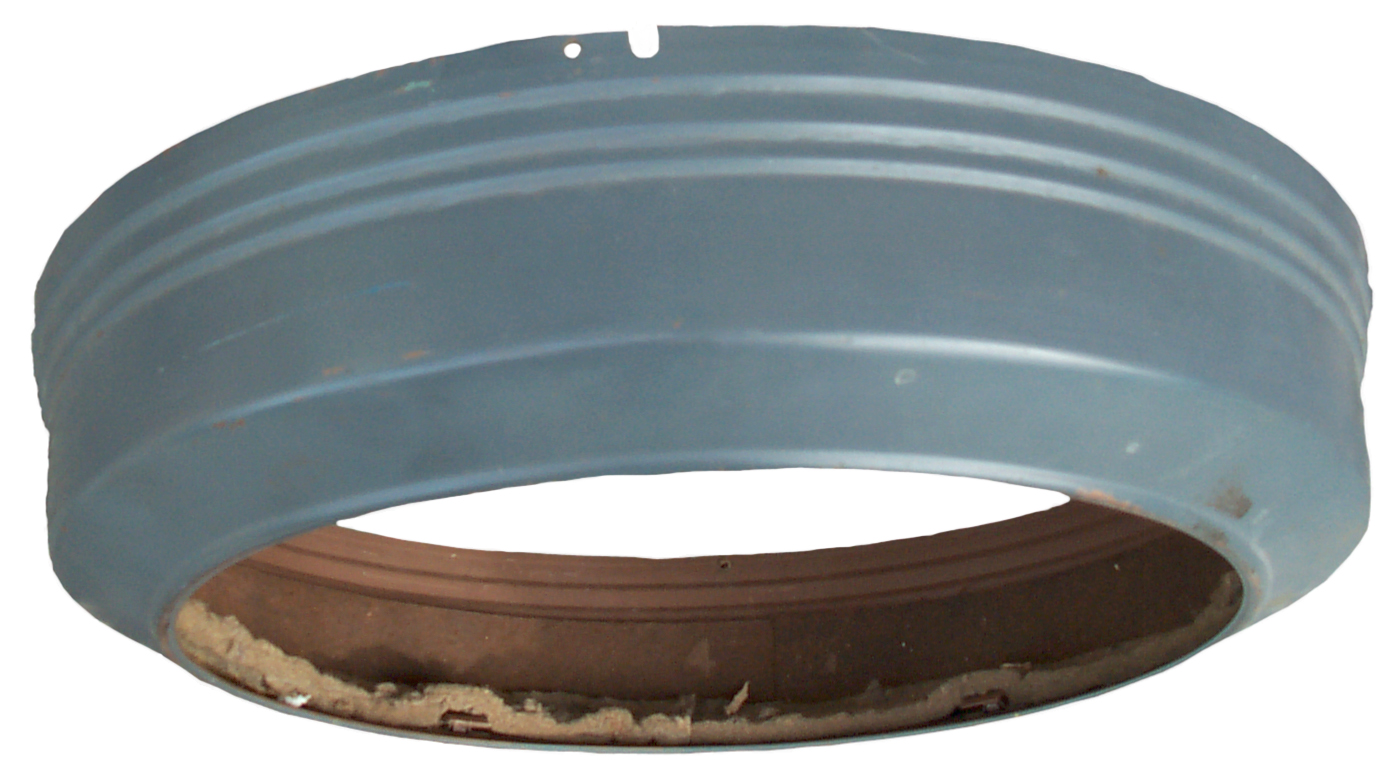
Round Case

I think the
color is battleship gray.
An approiate color for a USNO clock.
Missing glass as received.
Top hole for alignment pin and notch for top wire access.
Bottom threaded hole for missing attachment screw.
Glass Attach
Glass Attaches
with 5 clamps lined with what may be sheet cork?
The opening in the metal case is 14 & 13/16" so the glass must
have a larger diameter.
The distance from the opening edge to the inside metal bracket is
hard to measure exaclty but using the minimum rradial distance
of 0.512 gives a max diameter for the glass of (14.8125 + 2*
0.512 =) 15.8635".
The cork (?) material is about 0.050" thick so the glass should be
less than 15.8635 - 2* 0.050 =) 15.7635" diameter.
The black goop was holding sound deadning material to help cut
down the noise for use in radio and TV studios.
Cleaning
Naphtha (
Wiki)
(aka: White Gas, Coleman Camp Gas, Lighter Fluid, Benzin
, Petroleum Spirits,
Ronsonol, Ligroin) or a commercial clock cleaning solution can be
used. Many of the commercial clock cleaners contain ammonia
which can be harmful to brass if not thoroughly rinsed.
The electrical and fiber parts should not be cleaned in any of
these solutions since they will be harmed. This means
disassembling the movement. That means how do you get it
back together. This is where a digital camera and maybe
making some drawings is a good thing.
The minute hand shaft shows some slight wear. In the
worn bushing photo you can see black goo (oil
plus worn brass bits) on the end of the shaft which in a normal
clock would be for the minute hand. This clock is unusual in
that there are no hands on this shaft and instead they all are
centered on the second hand shaft. The post to the left of
the minute shaft holds gearing. In the background you can
see the escapement wheel. The large gear driving the pinion
gear on the minute shaft is part of the main spring shaft
assembly.
At this point I've removed all the items that have fiber or
plastic parts getting ready for cleaning.
Also making drawings to be sure it can be put back together.
The tricky part is that there are adjustments that need to be made
during the assembly process which I'm still trying to understand
prior to dismantling the frame.
The frame has been opened. And more
photos and drawings being made. The small washer that fell
off the back frame plate came from the armature shaft. The
two screws that were removed to take off the back frame are
sitting on it over the holes they came out of.
Frame
This is the "F" movement, just like
the first S.W.C.C. clock. But this frame has additional
tapped holes to support that stub axle shown in the photo above
that are not on the more common "F" frames. There may be
other differences.
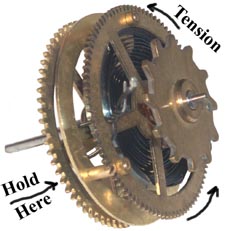
The mainspring barrel assembly after slowly
releasing the tension, it took 4.0 turns, which will be the amount
required for reassembly. The wheel leg that has the pin is
pointing to 12:00 on both wheels in the photo and that's the leg
that has the outer end of the spring attached. It's hard to
see but on the left wheel at 2:00 is a non threaded pin to the
outside of the spring, i.e. the spring is inside the 3 wheel
attachment posts and the pin. There is a loose
part in the center of the left wheel that connects the spring to
the shaft. The shaft has a pin that drives a slot in the "C"
part which in turn has a ball ended pin that grabe the inner end
of the spring.
Inspection

On of the
things that needs to be looked at is the slop on the hour wheel
where the black goo was. I tried using digital verneer
calipers, but it seemed I needed a hand to hold the clock down,
another hand to hold the capipers and another hand to work the
zero button. So changed to using a dial gauge that has it's
own stand. Don't bother trying to rotate the dial to zero or
using the little pointers (you can see one of them in the upper
right of the photo) since the zero will change. Just note
the reading before and after reaching through the hole in the
frame and lifting the shaft. In this case it moves about
0.007 mils.
I'd call it a little worn, but not enough to replace anything.
More Cleaning
The first cleaning with Naphtha removed the
caked on black combination of old dried up oil and metal
particles, but left a white film underneath where they were.
It took a couple of cycles in the ultrasonic cleaner to get them
clean. The image at the left was made using a flat bed
scanner. These work very well for flat objects, so the shaft
ends most forward are in very good focus and I can see the
scratches on the bearing surfaces.
Abrasive methods of getting rid of the scratches are not a good
idea since that makes the shaft diameter smaller. The
preferred method is to burnish the pivots.
Need to shop for a manual burnishing tool and pin vise that can
hold a 1.8 mm pin on Monday.
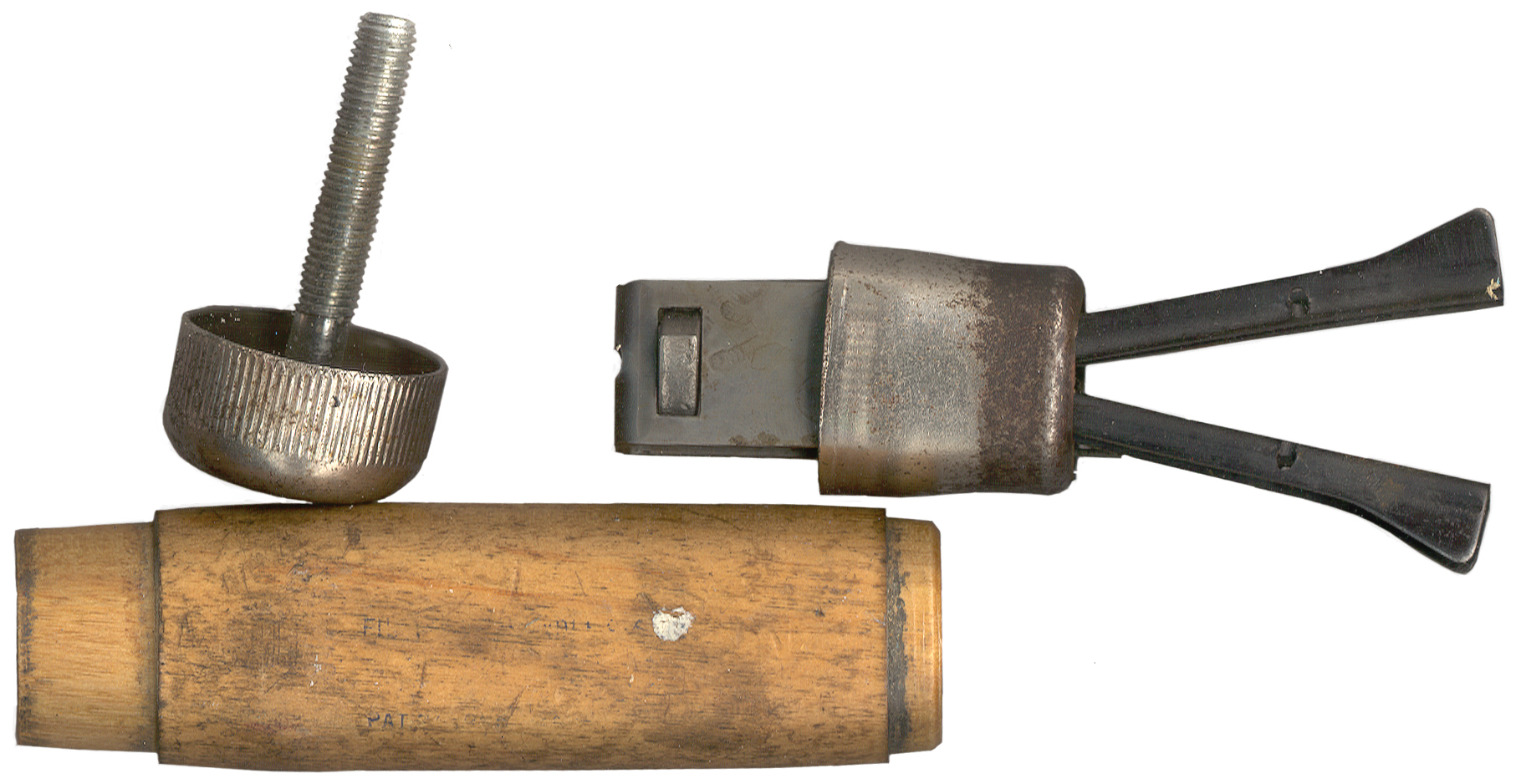
Burnishing
This is a process of deforming the
metal on the pivot bearing surface to remove scratches or
worse. Unlike abrasive methods of polishing, burnishing does
not remove any metal, it just moves it.
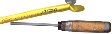
The brunishing tool (
Time
Savers 17526) is just a rectangular metal bar about 2.75 x
6.5 x 180 mm. All the corners are sharp 90 degree
angles. There's no way you can hold this in your hands and
working with it without cutting yourself. So I have
mounted it in a file holder handle.

The handle has traces of lettering and what looks like "PAT" but I
can't read it. If you know the brand or who sells this handle
please let me know.

The Pin
Vices are not the proper size. The Large Pin VIse ( TS 16537) and
the Pin Vise (TS 13424) both have about the same size (hold 1.98
to 2.35 mm) collet. But will holdneither a 1.72
mm pinion bearing surface nor a 3.05 mm arbor shaft.
The opposite end has no round hole and is designed to hold very
small diameter items.
Lubrication
Oils and greases can provide less
friction between moving metal surfaces. A bearing
should be designed so that the loading per square inch is way
below the limits of the softest metal used. But as the
bearing area increases so does the normal operating
friction. So some balance needs to be made.
If the oil dries up (lighter oils evaporate faster than thin oils
and they are faster than grease) then the metal to metal friction
can do damage. The other thing that happens to a clock
that's in an open atmosphere (a watch is in a sealed case) is that
airborne particles find their way to the oil surface and become
abrasives that grind up the bearing surfaces. I'm guessing
that a little of both effects had started working on this bearing
when the clock was taken out of service.
After some web surfing I think the main spring will get Mobil 1
Synthetic Gear Lube LS 75w-90 along with the main spring arbor
pivots. This is an all synthetic oil (good for not growing
stuff) that has a proven ability to reduce bearing friction.
So a thin coat on the spring should make for smooth and free
movement. This can be checked by manually winding and slowly
releasing the tension and watching how the spring moves.

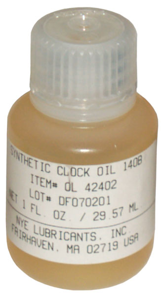
For the pivots
Nye
Clock Oil 140B.
Nye seems to be an up to date company not only conversant with the
approiate specifications for oils but also developing completly
new types of oils.
TAI
Lubricants - U.S. distributor with kits:
Damping Grease Kit,
Squeaks &
Rattles Kit,
Hobby
Kit,
Optical
Coupling Kit + individual products
Assembly
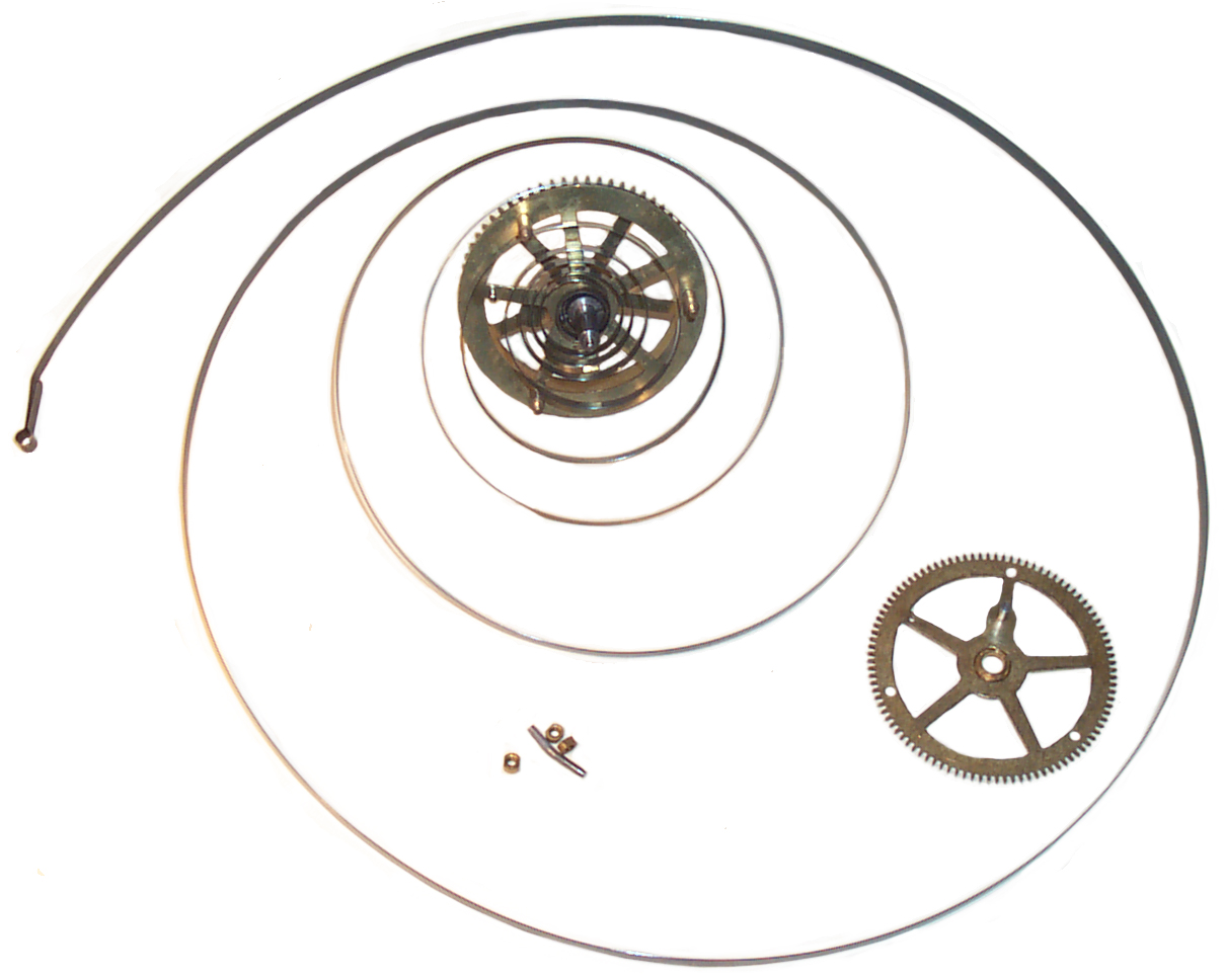
Mainspring Barrel

Here the spring has been looped onto the
center mushroom pin and is sitting loose on the barrel half.
I'm going to practice the winding on a dry spring, then lube the
spring and do it again.
I almost ruined the spring by turing the wrong way. It's
important that you tension the spring, not try to compress it.
After getting the spring on dry, used a tooth pick to pick up a
small amount of Mobil 1 "75W-90" and capillary action sucked it
between the turns.
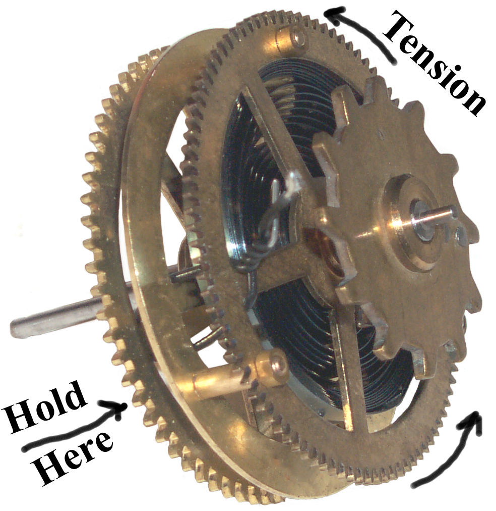
It takes strong hands to install the spring and keep it from jumping
away. If you have weak hands you might consider not taking
apart the mainspring barrel, or have someone else do it.
Then holding what is the front side in my left hand and turning the
back side (the side with the three nuts) counter clockwise put 4
turns of pretension into the barrel and tied it with a piece of
wire. See photo at left.
I've set the 5 minute wind cam on the shaft and it too got a tiny
film of gear lube.
You can see the wire is bent from the tension trying to turn the
rear gear (has the 3 nuts) clockwise.
DO NOT TURN
THE WRONG WAY!
Drawings
I have 95% of the clock in the form of an Autocad 2D drawing with
multiple views and many layers and many blocks. This allows
turning off layers to cause parts to disappear making for a clearer
view of the parts you want to see. So far have not proceeded
to make them into a parts book, but it could be done if there was
sufficient interest in purchasing it for some TBD price on CD-ROM.
The next thing that needs to be added is a table of threads.
For example the four screws that hold the dial to the movement are
4-40 x ¼ (or maybe could use a little longer screw) round head
screws. There are some strange by today's standards threads in
these clocks.
No. 6 Battery Adapter v1


This is the very economical adapter based on 2" sch 40 PVC pipe and
test end caps.
Construction
of Western Union Clock Battery Packs by
N7CFO.
If you're interested in getting a kit to build this adapter
let me know.
By putting two "D" cell batteries in one adapter the blue jumper
wire in the clock becomes redundant. This also lowers the
circuit resistance. The parts used inside the adapter were
also chosen for low resistance. The clock now winds much
stronger than when two seperate "D" cell battery holders were
being used.
It turns out that I already have the Rigid pipe cutter needed to
make a clean cut in 2" sch 40 PVC pipe.
Now I'm trying to find the 15.5" Convex glass to replace the broken
one. See Fig 4 above.
30 Jly 2006 - running slow. small move right on adj nut 9:00:00 am
synchronized.
5 Aug 2007 9:00pm 5:14 slow in 6.5 days or 48 sec/day _> 1/2 turn
Right
a couple of rough adjustments
29 sep 2007 sync at 3:00 pm
1 Oct 2007 - clock slow by 4-1/2 min or 135 seconds per day. one
turn on nut right
Need
Sound Deadending material to go into
front cover. The battleship gray cover has the material, but
it's been removed from this clock.
1 each need the thumbscrews to hold the cover on.
2 each screws to attach dial to movement
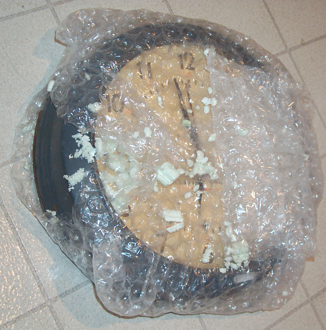
Questionable Packing

The box arrived crushed by a couple of inches. A box this
size probably gets put on the bottom of a stack that's 8 feet high
so needs to be able to carry that weight, either based on the
strength of the box itself or based on packing it so it can not be
crushed, or both. I suspect there's plenty of bubble wrap
around the clock but not enough to really fill the box. The
rule of thumb for radios is to have at least 4" of bubble wrap on
all sides that's taped tightly on each layer where the layers are
at right angles to each other. Then the box should have
stuffing at the corners and sides so that the item can not move
around. Then the box can be cut down so the top just covers
the item with more packing in the corners. When the box is
all tapped up and shaken there must not be any movement of the
contents. If there's any movement open the box and pack it
tighter.

This is poor bubble wrapping. There's only one layer and
it's loose, not tight to the clock. Thickness of bubble wrap
varies from 0 to maybe 1 inch, should be 4". The rest of the
box was filled with plastic peanuts. That would be OK if the
item had 4" of bubble wrap and if the box was "tight" so that
nothing can move inside. If there's any movement the peanuts
will crush with each shake, so it's a matter of time until they
are completely gone. With heavy items the peanuts can be
completely gone after a few hundred miles of shipping.
Note that shipping insurance is for protection from loss or
mishandling by the carrier, it DOES NOT cover damage caused by
this type of poor packaging. Many people don't understand
that it's the responsibility of the sender to properly package the
item, not the shipping company.
Really Bad Packaging by mickiecat1
Self Winding Clock #4
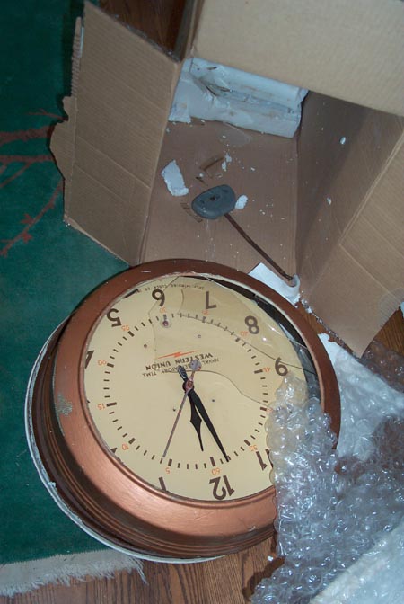
10 July 2007 -
received today via Fedex ground. This is not the fault of
the carrier, it's unquestionably the fault of the shipper.
This clock (s/n 59132) looked like it might actually run on eBay
and had the very hard to get glass installed.
In the photo you can see a fold to the right side of the box down
maybe 6". This is because the box was not full.
Another sign of bad packaging.
Notice the
packing above included a couple
layers of bubble wrap. But this one only had some small
pieces of bubble, but not wrapped or taped, just stuffed in.
The main packaging material was Styrofoam.
I specifically asked about the pendulum being bolted down to the
clock, since the eBay ad
showed
the pendulum sitting inside the clock, which was laying on
it's back, and no bolts were visible. I was reassured that
the pendulum was bolted down. As you can see it was
not. Sort of like putting a hammer in the same box with
something delicate and NOT securing them so the hammer can beat up
whatever else is in the box.
I've notified the seller, we'll see what happens. This is a
real shame since the glass was in one piece when it was
boxed. As far as I know you can not get this large glass
anymore.
15 July 2007 no word from the seller in response to my emial and
neither of my two phone calls has been returned. On the
first phone call I left a message. On the second call the
phone never answered.
18 July 2007 - the seller has called, but we're having trouble
exchanging email.
Somehow she felt that Fedex would pay for the damage caused
because she did not properly anchor the pendulum. I left
negative feedback for mickiecat1 but it cost me a retaliatory
negative feedback. The only one I've ever received.
The only worse packaging I've seen was when two lead acid
batteries were put into one box with Styrofoam. In that case
there was no Styrofoam left, it had all been crushed.
Note I did not unwrap the clock, this is how it came out of the
box, in fact it's still partially in the box. To the right
and down out of the frame there are sheets of styrofoam, not
bubble wrap.
Please, if you don't know what you're doing, do not ship items
that you will end up destroying.

The bob was tied down with a piece of wire when put into this
box. Only a half turn was used to join the wires and
with a bob weighing 24 ounces, about the weight of a framing
hammer for a big carpenter, you can be sure it will work it's way
loose.
I put the "knot" back together. There are many scuff marks
around the knot where the wire fought it's way out of the bob.
The clock frame and bob have two clearance holes for a 1/4-20 bolt
and using a wing nut makes it easy to install.
Fig 3 at top of page shows this clock (s/n
59132) running. The pendulum rod was bent, but straightened
out. It has the single coil synchronizer. No
synchronizer relay. A once per hour winding cam. This
clock winds less than a minute before
Self
Winding Clock Co. #1 winds at 38 minutes past the
hour. So it looks like the once per hour wind occurs at this
time.
New Way to Know the Rate
17 July 2007 - When you have two of the Self Winding Clocks
running in the same room one acts as an alarm clock each time it
winds. By noting the start and stop time of winding for two
clocks you can check their rate. SWCC #1 is within a few
seconds per day, but #4 seems to be running about 10 seconds per
hour slow.
10 Sep 2007 16"45 - 3 min 11 sec slow in 56 days or 3.4 sec/day
slow. 3/100 of a turn on the rating nut is very difficult.
Better to work on the synchronizer
Black Western Union, Naval
Observatory Time
Case is about 16 inches square. Dial window is about
10-3/4" diameter.
There are some mystery parts that came with this clock.
1. The 3V connector - battery holder???
2. The bent wire tool
What are they? Let me know.
Photos
Fig 1

|
Fig 2
 |
Fig3
Home Made Battery Holder?
Lamp Socket & Bicycle Spoke - nut.
What Battery?

|
Links
Back to Brooke's Time & Frequency,
Personal Home, PRC68
Home page created on 4 June 2007
[an error occurred while processing this directive]
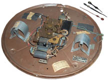 Fig 1
Fig 1 Fig 2
Fig 2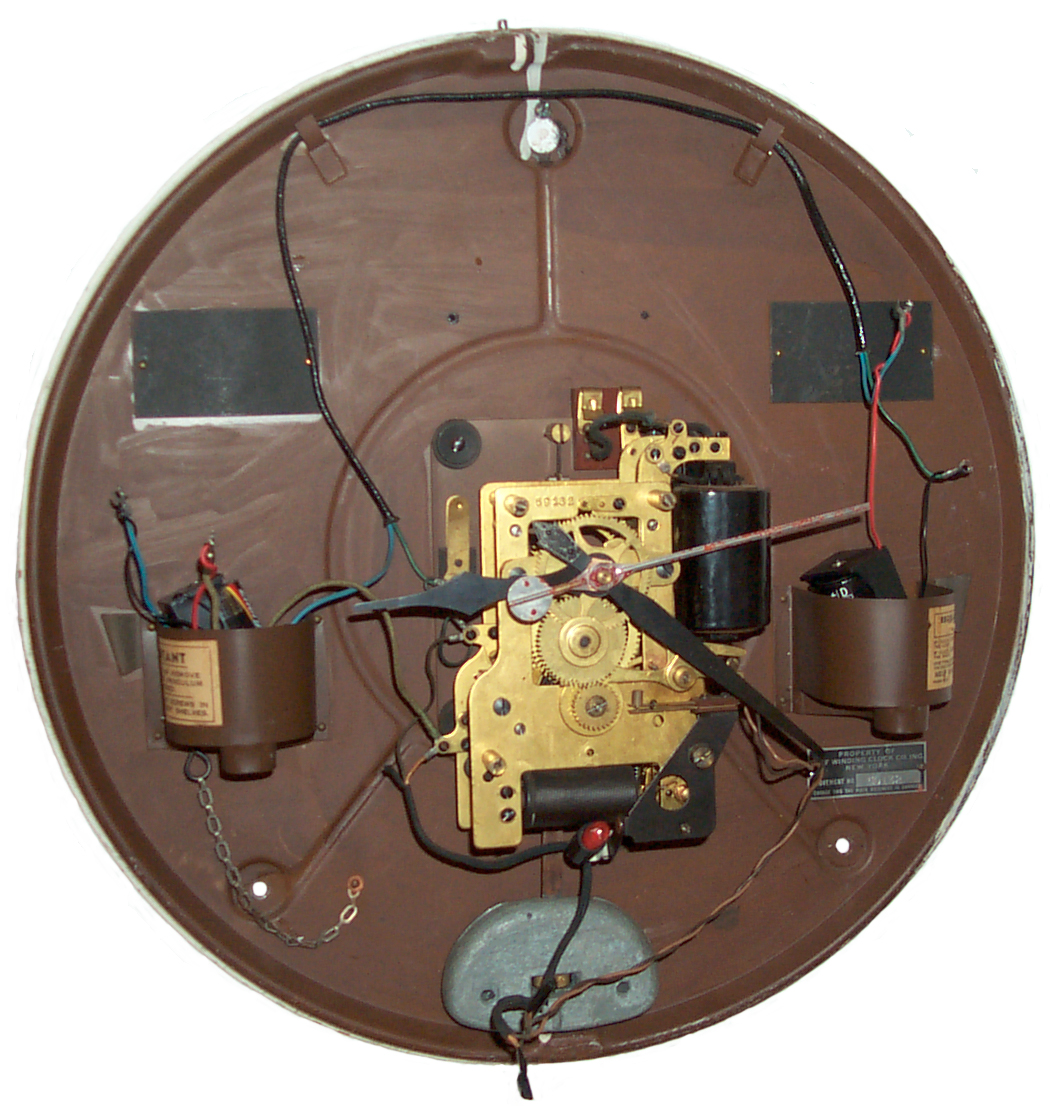 Fig 3 SWCC #4
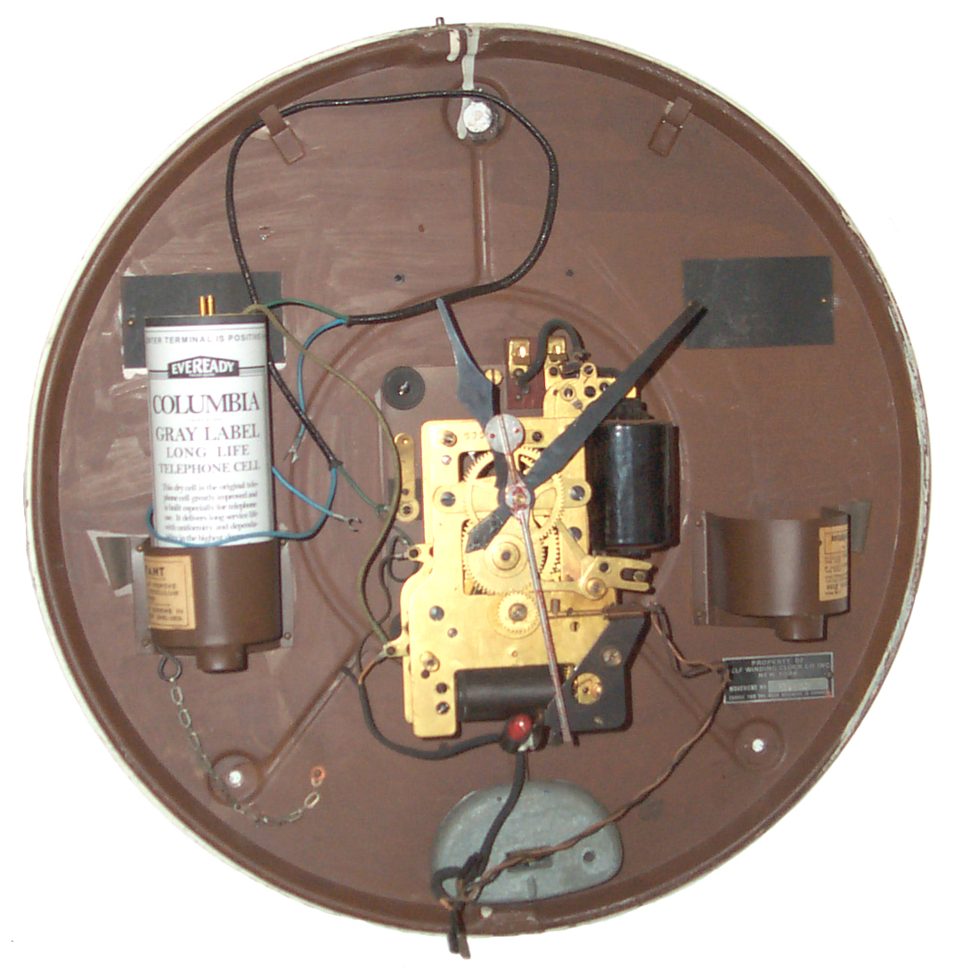


