TW100F/AT Transworld Datron Fly Away H.F. Radio
&
TW100UL Table Top
© Brooke Clarke 2012 - 2023
Background
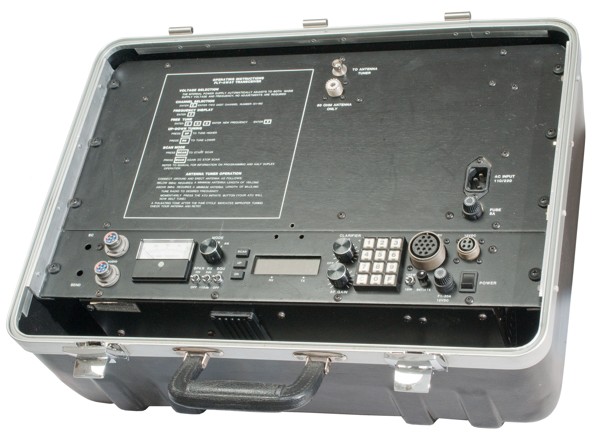
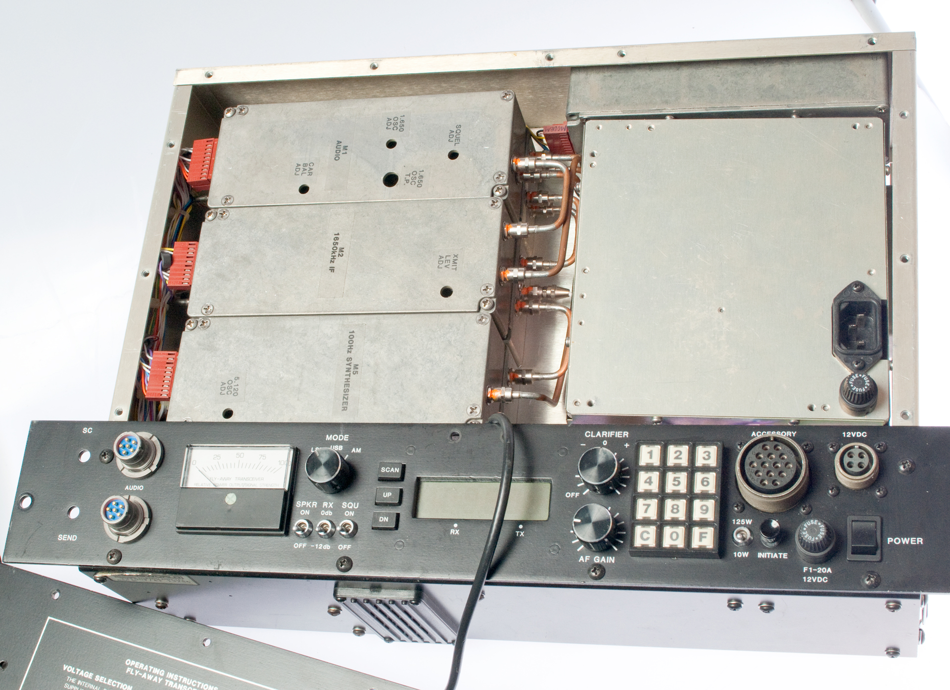
TW100 Fly Away
Connectors
DC Power Supply
AC Power Supply
Power Supply Comments by Jeff
Manuals
TW100UL Table Top
Related
Links
Background
TW100 Fly Away
Connectors
There are a couple of circular
connectors on the front panel.
Accessory - threaded
coupling, 14 socket contacts, core marked "20-27". Cable
conn: MS3106A20-27P(SR)
12 Volts DC - threaded
coupling, 4 socket
contacts
Cable conn: CA3106E12S-A10P
(This is an odd connector that Bill P. hand makes or is expensive)
DC Power Supply
The stock DC power supply is for "
12 Volts" DC. What is the
mating connector? It's an odd duck. It can be made by
turning down the diameter of a standard insert. Steve Hanney
can custom make them.
A common car battery would work
well.
There's an option for a "24 Volt" DC supply that would be
compatible with military vehicles and some aircraft.
There's a warning in the manual to not use both the DC and AC
supplies at the same time. It may damage everything.
The UPF7000 Power Supply is rated 13.8 V @ 30 Amps and it's PCB
looks similar to this one. But instead of using TO-220 power
devices it uses a couple of external boxed power devices.
I expect the technical info for this supply would be a big help in
troubleshooting my AC power supply.
J2 DC 4-pin connector
Pins
|
Function
|
A & B
|
+14 VDC
|
C & D
|
Ground
|
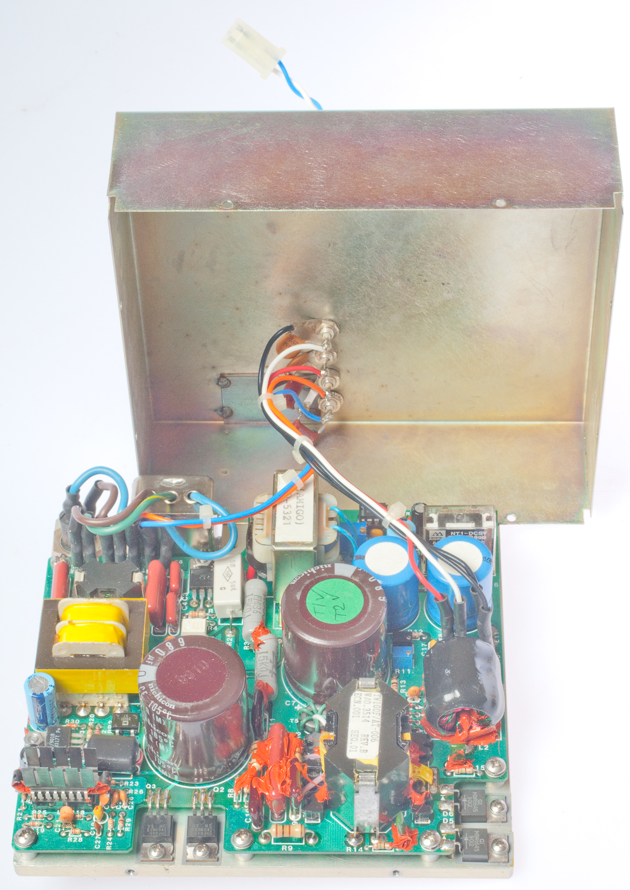
AC Power Supply
Dead, needs repair. If you have any documentation on this
supply let me know.
Uses the common IEC line cord.
Works with 50, 60 or 400 Hz and pretty much any line voltage in the
world. This radio does not have a selector switch for the line
voltage, so the AC PS module is truly universal. That solves
the problem of selecting 115 VAC and plugging into a 230 VAC outlet
and letting the smoke out.
Power Supply Comments by Jeff
The biggest problem with that setup, and I do like the concept,
was the BNC interface cable. Transworld used a crimp type
connector, and it had a tendency to short out, and when that
happens it will blow the PSU in short order, it blows the output
FET right off of the board.
I worked for Transworld when this unit was developed. The first
revision of the PSU utilized a relay that would select the voltage
Mains input. That relay was to sensitive to vibration and if it
did happen to throw the contacts it would blow the PSU in short
order as well. The later revision of the PSU, and I do believe we
recalled all of the first revision units, was an auto sensing of
the mains and the PSU worked very well after that.
So your problem most likely was the Antenna connection cable.
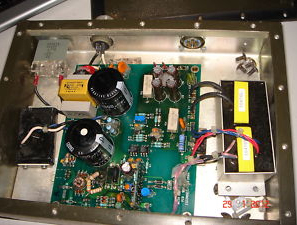
Inside the AC Power Supply

|
Marked:
TWC 738168 Rev. A
Transformer marked:
TW100F/AT-006
W/.O 3514 Rev. B
ECN. 001 Seq. 01 |
Wiring Table
PCB
|
Wire
|
Component
|
External
Wire
|
|
E1
|
Brown
|
Filter
|
-
|
|
E7
|
Grn/Yel
|
Filter
|
-
|
|
E2
|
Brown
|
Fuse
|
-
|
|
E3
|
Blue
|
Fuse
|
-
|
|
E4
|
Org
|
Feed
through
|
white |
On/Off Switch
|
E5
|
Blue
|
"
|
Blue
|
On/Off Switch |
E6
|
Blue
|
Filter
|
-
|
|
|
|
E8
|
Red
|
Feed
through |
Red
|
E8=E9: +
|
E9
|
White
|
"
|
Red
|
E8=E9: + |
E10
|
Black
|
"
|
gnd
|
E10=E11: -
|
E11
|
Black
|
"
|
gnd
|
E10=E11: - |
|
Connecting to the 115VAC mains -
there is no DC output (with a jumper between E4 & E5).
BR1 shows 122 VAC and 355 VDC.
ESR-Cap Testing
No.
|
Marked
|
Meas
|
ESR
|
C6
|
680 uF
250WV
|
681
|
0.07
|
C7
|
680 uF
250WV |
677
|
0.45
|
C15
|
3900
uF 16 VDC |
9600
|
0.03
|
C16
|
3900
uF 16 VDC
|
9610
|
0.04
|
C28
|
470
uF 35 VDC
|
450
|
0.47
|
C33
|
100
uF 16 VDC
|
105
|
0.40
|
(R30)
|
470
uF 35 VDC |
455
|
0.15
|
(R17)
|
330
uF 16 VDC
|
137.4
|
1.02
|
3 March 2012 - 330 uF @ 25V caps on
order. Replacing the cap next to R17 with a 330 uF 35V cap
did not fix the power supply.
Maybe C15 & C16 have a problem since they show too much
capacity? Probably in parallel with other caps.
RF Amp Transistors
Replacement for D310050: SD1487
Substitute transistors: MRF422 or SRF3503P
Manuals
I've found a couple of manuals on
line. But neither of them matches this radio nor includes
info on the TW AC power supply.
TW100 Microprocessor Controlled
HF SSB Transceiver, Pub No. 990101, Apr 1987, 319 pages -
includes technical info
TW100F Fly-Away HF SSB
Transceiver Operator's Manual, TW100F-MSOP Pub No.
990160, Sep 1990, 69 pages - is for a fly-away radio that looks
similar to this one, except there is only one U-229 AUDIO
connector and has jacks for headphones and a Morse key. No
technical info.
TW100F Fly-Away HF SSB
Transceiver Technical Manual, Part No. TW100F-MS, Dec
1992, Rev H1 (3 parts combined = 216 pages)
The tranceiver covered has one U-229 audio connector and 1/4"
phone jacks for a key and headphones. My radio has two U-229
audio connectors and no jacks.
The tranceiver covered has a very simple AC power supply. My
radio has a complex AC power supply.
TW100F Fly-Away Transceiver Condensed Antenna Tuning Instructions,
Pub. #990177, Nov. 1990 - seems to be for an antenna tuner that
has controls.
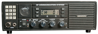
TW100UL Table Top
This is a table top HF transceiver. Note there is no
provision to tune to a frequency, the radio only has channels.
Pressing "C" then two digits sets the radio to that channel.
Pressing "F" displays the frequency of the current channel.
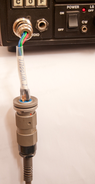
Fig 1 Front
|
It's not clear if the 1/4" jack is for a
mike or speaker.
|
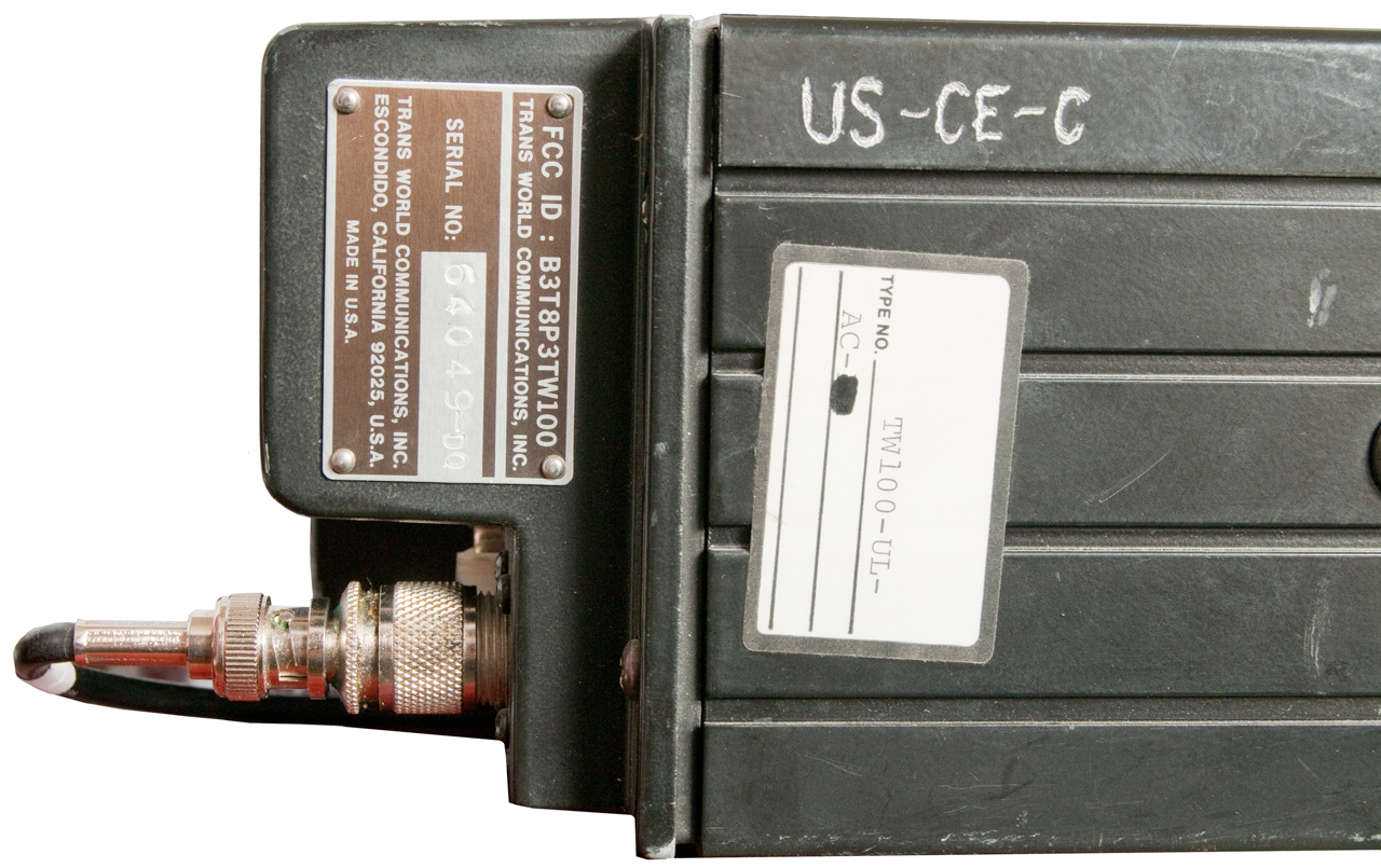
Fig 2 Label

|
|
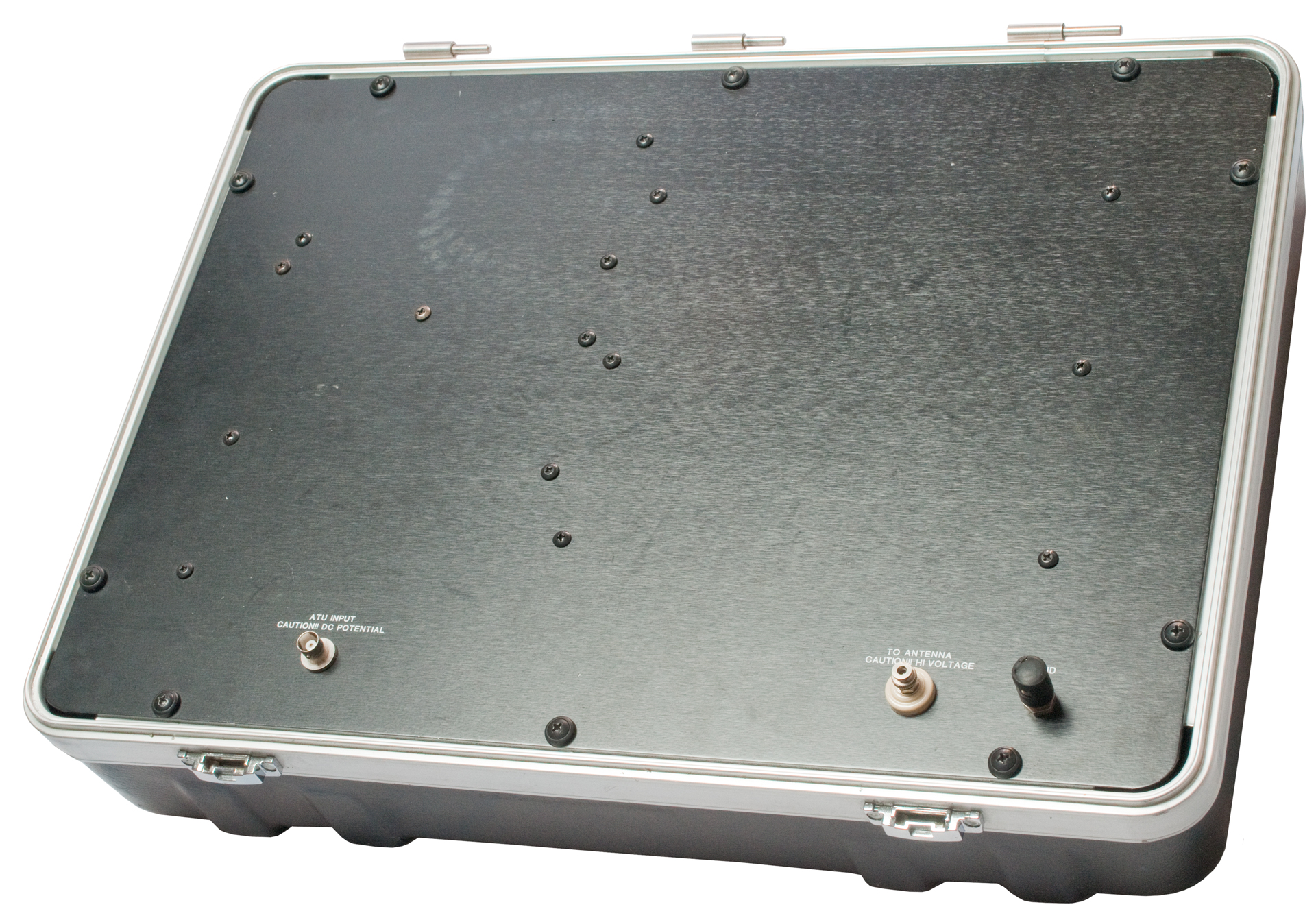
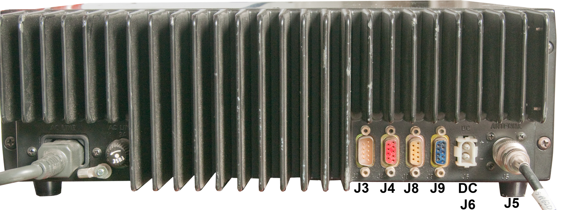
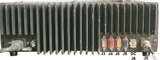
Fig 3 Rear
|
It's not clear what the purpose or pinout
is of the DB-9 connectors:
J3 (yel)
J4 (red)
J8 (yel)
J9 (blu)
and Moxex connector (model No.?) for 13.6 VDC power.
|
Fig 4 Audio Connectors
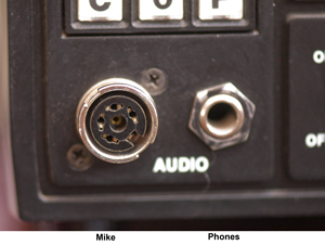
Mike 4-Pin Connector to make cable:
Mouser Part Number: 502-09CL4MX
Fair Radio Item
8817
|
|
|
|
Adapter Cable: TW100UL - U229
|
|
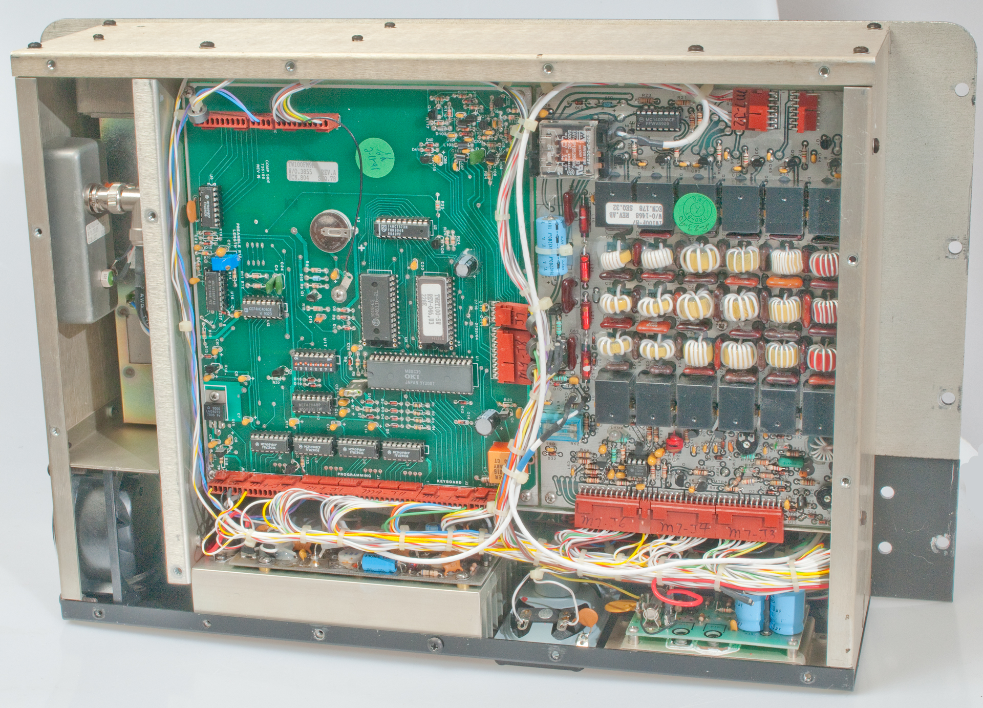
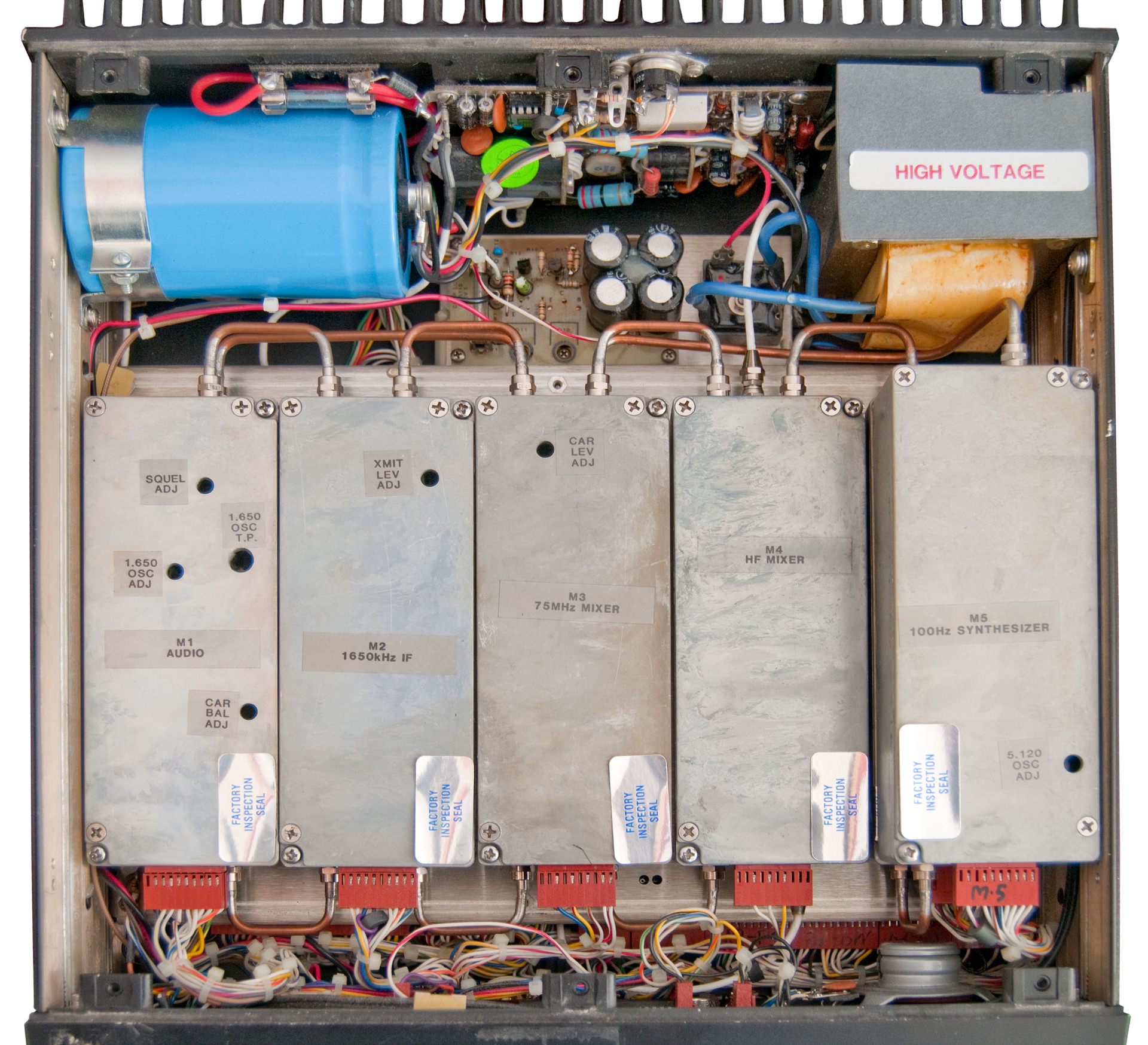
Fig 5 Top Inside

|
|
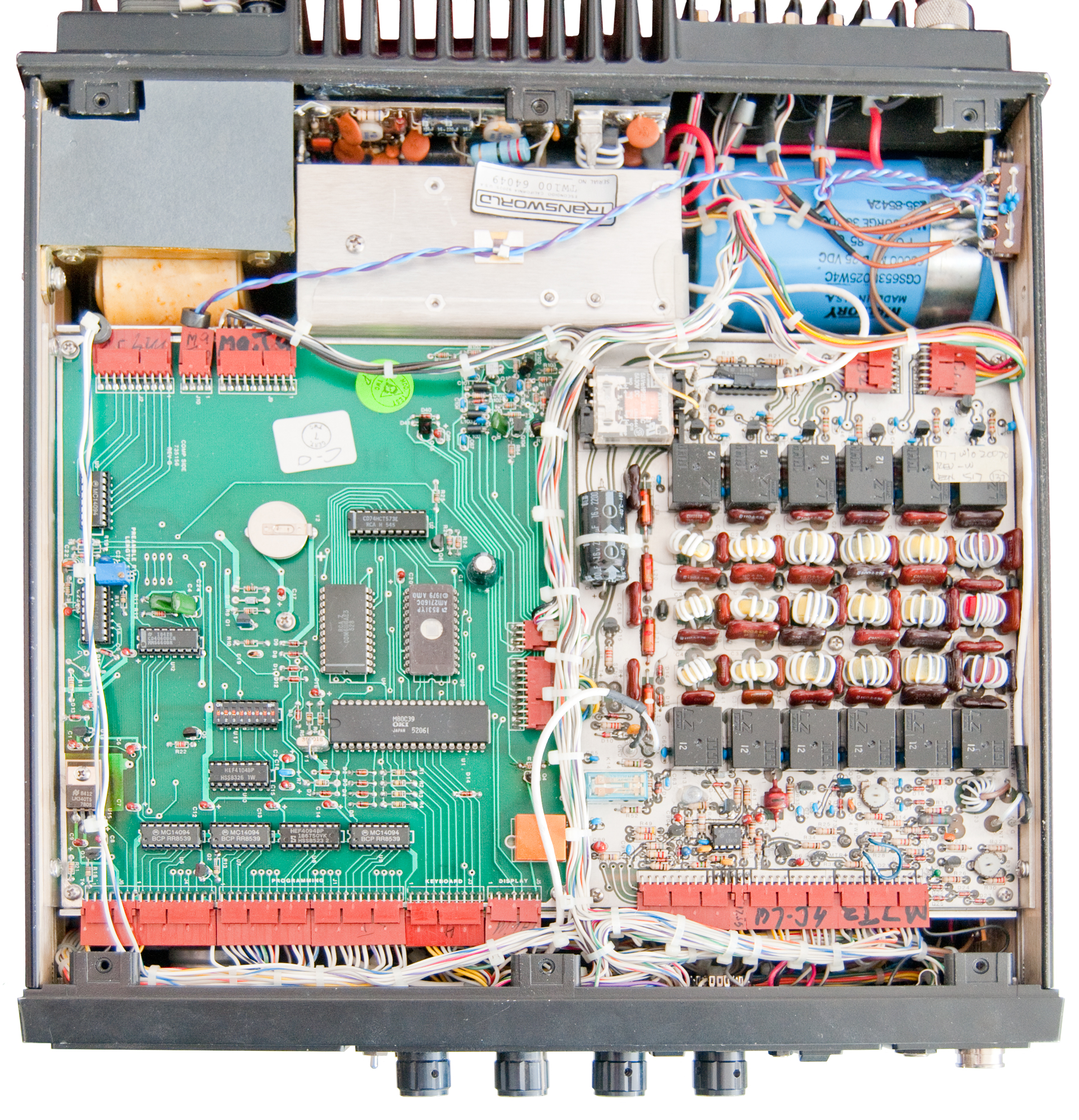
Fig 6 Bottom Inside
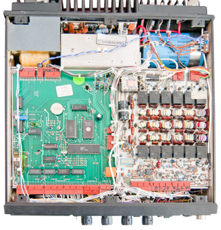
|
The memory coin cell battery is at 3.043 V which is like
new.
|
Manual
TW100 Microprocessor Controlled HF SSB Transceiver Operators
Manual, Publication #990139, December 1984
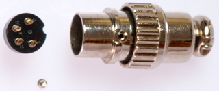
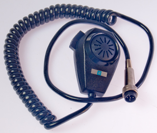
GM Delco mobile mike
Got a GM Delco mobile mike from Fair Radio in the hopes it
would fit one of these radios, but alas it does not fit either
of them.
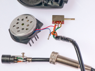
The connector has 5 male pins.
The OD of the black mating tube is 0.519 and it's ID is 0.437"
 |
Connector Pin Out
Violet
Gray
Orange
Green
Ground
Vio & Gry: PTT
|
|
|
Related
Harris RF 3200ET
Fly Away H.F. Radio
TW7000F Flyaway HF Tranceiver
ICOM IC706 Mk II G
ICOM R7000
NRD545 Receiver
Links