 |
 |
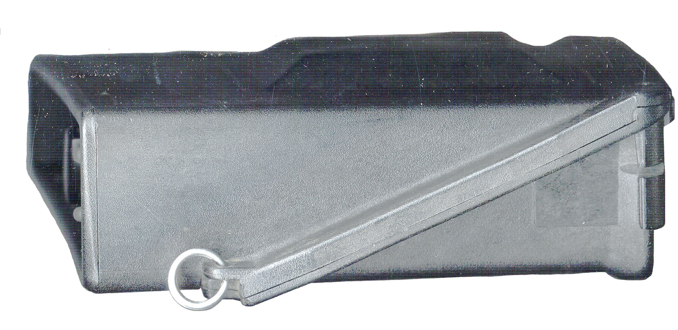
 8 AA Battery Box 13828-00 |
I have seen Trimpack, Trimpac, Trimpak, Transpack, Transpac and Transpak, Spartan. Don't know why all the different names. I've tried to separate some of these based on some manuals but if you know more about the names please let me know.
The first generation of GPS receivers used conventional receiver design. The second generation used a Digital Signal Processing (DSP) chip or a custom DSP chip and processed only a small number of channels (4 is the minimum number of satellites needed for a fix, but a receiver with fewer than 4 channels can be used by time sharing one or more channels.). The first Trimpack type GPS receiver was only a 2 channel unit. Later models were 3 channel and the last in the series were 6 channels where 4 channels were always tracking the best 4 satellites and the other 2 channels were searching for better satellites.
Modern (2003) GPS receivers are 12 channel designs and can track all the satellites in view. This has a big advantage because the receiver does not need to drop one satellite to acquire another. Since there are 24 satellites in orbits that are relativity close the the Earth, only about half of them can be seem at one time so 12 channels is an optimum number for a GPS only receiver. If the receiver can also track other navigation system then more channels are a good thing.
There are a number of Differential correction transmitters operating in the 283.5 - 325 kHz Low Frequency band and when their data is fed into a GPS receiver it's accuracy is improved. There's also a WAAS system using geostationary satellites to send the same type differential correction information, but the satellites have much wider coverage than the local DGPS transmitters. The Trimpack receivers that have a Computer I/O connector can take advantage of the LF DGPS signals by means of a separate LF receiver, but can not use the WAAS signals because to do that requires a fundamental change to the signal correlator.
In the book Armored Cav by Tom Clancy, 1994 (ISBN: 0-425-15836-5 Amazon.com) there is a lot of space devoted to the Trimpack GPS receivers on pages 173 through 181, maybe the most pages devoted to a single system.
Selective Availability
GPS was designed so that military users, who have receivers that can receive both the L1 and L2 frequencies and who have the required cryptographic keys, can get much more accurate results than the civilian L1 only receivers. Once there were enough satellites operational it was discovered that the L1 only receivers worked better than the system designers thought they would so Selective Availability was implemented to degrade the accuracy of civilian L1 only receivers for positioning applications. This was done by dithering the clock and maybe by changing the navigation data. SA did not degrade the results from the military Precision Positioning Service (PPS), only for the civilian Standard Positioning Service (SPS). On May 2, 2000 SA was turned off, they say permanently.
When SA was on there was typically one satellite that did not have SA turned on. This could be used for precision timing in a position fixed mode where only one satellite is needed for timing.
During the gulf war the SLGR, L1 only receivers were needed in the desert and so SA was turned off. Prior to 2 May, 2000 there were other occasions SA was turned off like to search for a downed plane and the CAP was using civilian GPS receivers.
Note that now, with SA turned off, all the Trimpack receivers seem to get within 0.1 arc seconds ( about 10 feet) very quickly after a warm start. Using just the civilian L1 C/A code.
The Magellan GPS NAV 1000M was also used in the first desert war.
Texas Manufacturing Facility
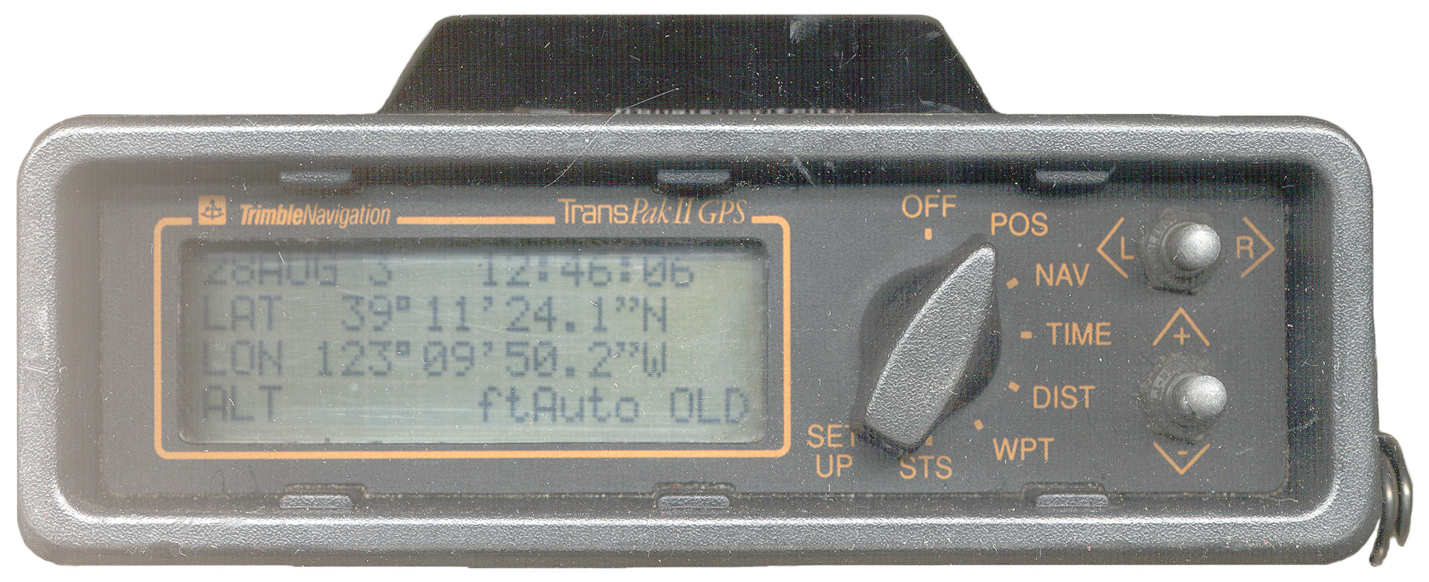
When the Trimpack II arrived the POS display showed:
30:23:15.5 N 97:42:45.9W 918 feet.
This turns out to be where it was made.
This is where the Trimble factory was where we built Trimpacks, some marine products, most handhelds, and most of the aviation products.
Trimble opened the plant in 1990 when they acquired the Omega/VLF aviation product line from Tracor Aerospace (now BAE Systems). This was Charlie Trimble's effort to leapfrog into the aviation business since Tracor had a land based navigation unit he could engineer a GPS module into. The idea was to extend the life of the Omega/VLF navigator line by making it a dual sensor and FAA certifying it. I was part of a small group acquired from Tracor who had the certification expertise and who set up the operation there in Austin.
To mention just of few of aviation firsts, Trimble developed the first standalone GPS panel mounted navigator, the first dual sensor certified systems (Omega/VLF/GPS and LORAN-C/GPS), the FAA certified dual mode sensor (SPS-PPS with SPS-PPS on-the-fly switching).
When Trimble sold some of the aviation products to Honeywell and Freeflilght Systems, they closed the plant in 2001 and moved everything back to Sunnyvale.
So those coordinates you are asking about is where your Trimpack was born! : )
A Reliable Source
These receivers were intended for use in battery powered man carry applications or mounted in a ground, air or water vehicle using a battery pack or a common 12 or 24 Volt vehicle power supply.
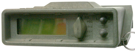
Front Panel
LCD
The Front Panel has a 4 row by 20 column LCD that is backlight (off, 1, 2,3 intensity settings). The LCD is of the type that is best viewed from straight on. If the Trimpack is hung around your neck using a camera type strap then when you look into the LCD, it will have good contrast. When the vehicle mount is used you also look straight into the display. The PLGR display is designed for 6 o'clock viewing (from below straight on, and so is impossible to view from above, like when it's in a vehicle mount that's below eye level.Switches
To the right of the LCD is an 8 position Function switch and to the upper right of that there is a 2-way momentary switch that works left-right, L-<center<-R. Below this switch is another like switch that operated in the Up/Down axis marked INC -<center> DEC.
By using the Function switch to select the overall function and then the INC/DEC switch to get to the sub menu, then the L/R switch to get to an item, then the INC/DEC switch to change the item, then the INC/DEC switch to move to a new item a lot of parameters can be seen or set. Although the forgoing description seems long, the menu navigation is very intuitive, but it can be tedious.
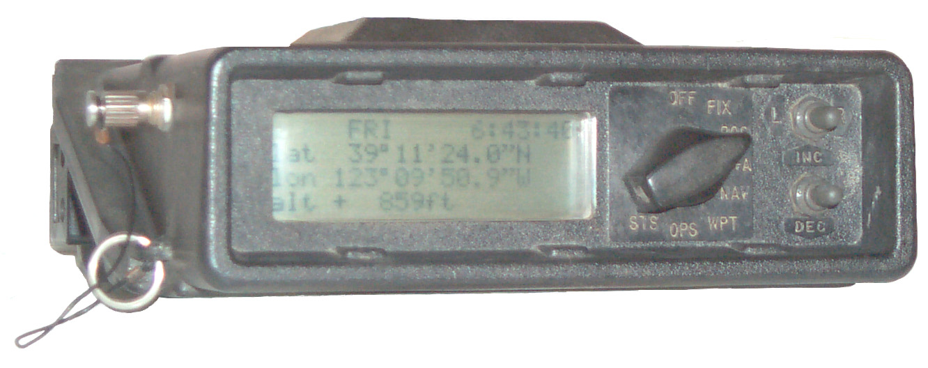
Latitude and Longitude Display
The display of Lon. and Lat. is to 0.1 seconds. One second of Latitude corresponds to about 100.338541 feet anywhere on a spherical Earth. One second of Longitude depends on where you are ,COS(Lat), at the Equator is the same as for Latitude and at the poles it's 0. For my Latitude it's 78.5416666 feet. So a tenth of an arc second is about 10 feet N-S and about 7.8 feet E-W for me. Placing the Trimpack on known objects and allowing 400+ averages (400 seconds) results in errors of about 40 feet in all three dimensions (2003 i.e. SA is off).
The Altitude displays to 1 Foot. Note that 0.1" of Lat or Lon is about 10' or 7.8' and so is about 10 times more coarse than the altitude reading step of 1 foot.
When averaging, within about a day the Lon and Lat were reading the correct value to the 0.1 arc second level, which is as precise as this unit can display, but the altitude took a few days to settle down to +/- a couple of feet. The averaging counter seems to count up to maybe 32, 000 and something, then count down, and up, etc. with strange characters being displayed. For example now it's counting down and just rolled over from -Exxx to -D999.
The 14992-20 is connected to the 28367-49 mag mount antenna which is on the rain gutter. It's average altitude is 891 and the mast mounted antenna feeding the AN/PSN-10 is reading about 900. The 9 foot separation may be reasonable. It takes about 2 days of continuous averaging to get the elevation to 902 +/- 1 foot. But it only takes maybe an hour to get the Lat and Lon to stabilize to within 0.1".
1 Connectors A = Antenna, P = Power, K = Key Load, I = I/O
Trimble p/n Description # Chan
Color
NSN Con1
FW
Comment
12545-00 SLGR- Trimpack 2 L1
5825-01-356-7849 A P I 1.05c, 1.06f, 1.08a
Not very good performance with only 2 channels
14992-00 TransPak 3 L1
1.03a
1989 - shows Receiver Fault (16) with ext ant.
14992-00 TransPak 3 L1 Black
2.05 1989 - does not show error (16), so changed ant cur sense
14992-20 TransPak (SPARTAN)
3 L1
5825-01-364-6283 A
2.02b
14992-30 TransPak 3 L1 ?
4.2
14992-60 Pathfinder 6 L1 Black na
14992-70 TransPak II 6 L1 Black w/Org Ltr
A, I 4.10
14992-81
Pathfinder Basic XL
6 L1
Bloack case Yel Frnt Pnl
na
A I
16768-002 SLGR- Trimpack
3 L1
Green
5825-01-357-5506 A P I
16768-102 SLGR-Trimpack
3 L1
Green 5825-01-357-6171 A P I 2.02a Have Quick 1 PPS output
F04701-890C-0087
16768-202 SLGR-Trimpack
3 L1
Green 5825-01-357-6170
A P I 2.02a
2.05a
2.05c
Have Quick
16768-30 SLGR-Trimpack 3 L1
A P I
16768-65
SLGR-Trimpack 6L1
Green
?
A P I 2.07
green backlight. boss on right for key fill
16768-66 SLGR- TGPS II
3 L1
Green
Black Knob
A P I
2.07
Have Quick more than 26 WP, maybe not 1089
16768-66 Trimpack II
6 L1
Green
Green Knob
A P I
2.13B
STATIC HQ, Have-Quick IIA, STATIC PPS, PulsePerSec, OFF
16768-67 Trimpack II 6 L1
Green
Green Knob?
A P I
2.13B made in 1994
16768-80 Graphics Trimpack
6L1
Green
1.15
2.52
8/11/1992
Graphics Display
16787-20 Pathfinder Basic+
6 L1
black?
n/a
A, ?
GIS mapping
18154-00 Centurion 6 L1P L2P
A P K
same as SAGR AN/ASN-169
L2 requires external antenna
19437-60 TransPak II
6 L1
4.10
20636-00-IN SAGR, AN/ASN-169 6 L1P L2P Black 5826-01-414-4147
5825-01-383-3377
6605-01-383-3377
6065-01-383-33773
A P K
23365-00 Trimpack III
A P K
Firmware does not support Key Load
TB 5826-314-10
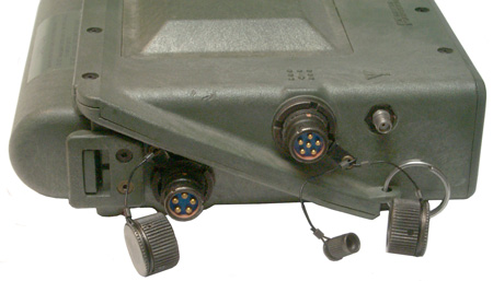
The Left side of the 16768-20 AN/PSN-10 has the External Power connector at the rear and the Computer I/O connector just behind the External Antenna jack. The other views are the same as for the 14992-20 except the color is green instead of black. The backlight in the 16768-20 is white, not red like in the 1499-20.
8 AA Battery Box 13828-00
Documents
Title
p/n
Applies to
Ref Man
13498
12545-00
Ref Man 13498
16768-00 (Red Screen)
Ref Man 13498 A-D
16768-10 (Have Quick, Green scrn)
Ref Man 13498
16768-20 (Green screen)
Ref Man 13498 A-E
16768-30 (1089 WPTs)
Firmware
The firmware in this receiver (V 2.02a) is identical to the to the firmware in the 14992-20 Trimpack. The Function switch has the same labels on each position and the menus are the same as the 14992-20. The firmware is contained in 4 each 28 pin chips (probably ROMs or EPROMS, but not EEPROMs) but they are in sockets that have 32 pins so maybe larger firmware programs can be retrofitted or are used in other versions, maybe like the Centurion. The existing 28 pin chips might be the 27256 EPROM, 256k bits, 32k Bytes per chip.
If you have a Trimpack please let me know the part number and firmware version of your receiver.Computer I/O
The STS menu page has these 3 choices for Computer I/O:
- Trimpack - This is the standard I/O protocol
- Track-2 - This allows data logging and post processing, maybe carrier phase?
- OFF -
Using a Passive cable between the RS-422 output of the AN/PSN-10 and my desktop DB-9 RS-232, with the AN/PSN-10 set for:The AN/PSN-10 will track satellites when inside a two story house, but nowhere as many as It will track outside on a hill.
Data Port -- TRIMPACK The following binary data packets are being sent:
41 GPS Time
42 Single-precision Position Fix XYZ ECEF (every second)
43 Velocity Fix, XYZ ECEF (every second)
44 Satellite Selection
46 Health of TRIMPACK
49 Almanac Health Page (when received from sat)
4B Machine/Code ID & Additional Status
5B Satellite Ephemeris Status (when new sat is acquired)
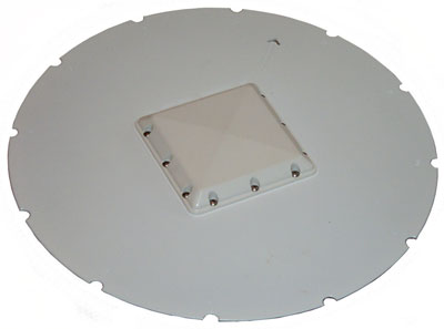
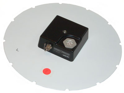
The following photos are of a 16768-80 SLGR. It appears to have a display capable of either alphanumeric or graphics. Firmware version 2.52
All the prior Trimble GPS receivers I've seen in the Trimpack family have had 4 row x 20 column LCD character displays.
This particular non working GPS receiver model 16768-80 appears to have a graphics capability. There's a "graphics piggyback" PCB that's connected in parallel to all 24 ribbon cable wires going between the CPU board and the front panel. The NEL-D3-045(A) is on the "graphics piggyback" PCB and has it's "G" pin connected to the Ground bus as well as pin 15 which is one of the two function switch control lines that seems to be shorted to ground, i.e. does not change with switch position as I think it should (which might prevent the unit from turning on).
In the status menu pages there is a language selection with options for English or Arabic. That's why the graphics screen.
Although the 14992-20 receivers tollerate the 28367-40 Mag Mount Antenna, the 16768-80 gives a Receiver Fault (16) error message and shows INT Antenna. Switching to the 17572-00 shows EXT Antenna.
The prior versions of the receiver have had a backlight for the display that had 4 brightness levels.
Regarding the EL HV module. Upon close visual inspection there appears to be No Connection to the "NC" terminal. The "O" terminal goes to pin 11 is the Output. The "I" (In) terminal goes to a circuit node next to the HD61830B00 Graphics controller IC consisting of a couple of transistors, a couple of caps and a couple of resistors and maybe related to an LM2904 dual op amp.
Assy 14533-00 Rev B
At the lower right corner you can see the narrow edge of the "graphics piggyback PCB and just above it the brown socket for U8 which has not chip installed. That socket is on the analog board, not the (in this photo) top digital board.
If you look at the Transpak L1 3 Channel receiver analog board below you can see that the socket is not installed but the PCB board supports it. So the function of U8 is not part of what's needed to recceive L1 GPS.
Adjacent to the U8 socket is a hole pattern labeled J4 with 5 holes for pin numbers 1, 3, 4, 5 & 6. This is the location of the key fill cable that is not present on this receiver so U8 is probably the crypto chip. Also adjacent to the U8 socket are pads for R53, R54 and R55 that have a trace shorting them out. So when U8 is installed these are probably scratched open and maybe resistors installed.
Nearby components R21, Q3 and R20 are not installed.
There are two (u17 & U18) Trimble custom DSP chips installed. That means this is a 6 channel receiver. Maybe L1 and L2?
The power supply shorting cap is defective. The three pins are either broken or moved back allowing the cap to rotate 360 degrees. It would not properly short all the pins to allow internal battery operation.
They were loose. Held in by glue or ???
Cleaned and used Loctite 290 to capture them. Now working fine.
Trimpak 14992
Version 2.02 28 pin EEPROMS.
Only 2 RAM chips and only the U17 DSP chip = 3 Chan receiver
Jumpers (probably relate to RAM and EEPROM size):
JU1 & Ju4 next to C22 not installed
JU2 & JU3 next to U10 & U11 not installed
All four of these are installed in the SLGR V2.52 board immediately below.
Lower Left 68 pin chip is the 68HC000.
The address lines go to the RAM and EEPROMs in a direct manner. But since the RAM and EEPROMs have only 8 data lines the data bus is split.
U8, U9 U12 & U13 carry the lower 8 bits and U4, U5, U10 & U11 carry the upper 8 bits. (U4 & U8 not installed in this photo)
Assy 14533-00A
The right hand 32 pin socketed EEPROMS top to bottom:
-----U10------
22166-01 U10
V2.52 C5A3
------U11------
221166-02 W5
V2.52
8238 U11
------U12------
22166-03 W5
V2.52
E2E8 U12
-----U13------
22166-04 U13
V2.52 60D6
The UV type PROMs are 8 bit 27C0101s and used in pairs (U10 & U12) , (U11 & U13) to make a 16 bit memory for the 68HC000.
The four center 28 pin RAM chips are marked:
16593-01
ISE/9250
and there are pads for 4 more RAM chips.
U17 & U18: TNL 17606 © UUBI9249
U15, U16 & U20 same as in the Transpak 14992-20
The battery is marked:
Z/05/91
Lithium Battery
3.6 Volts
Size AA
WARNING: Fire, Explosion or Severe
Burns May Result if Mistreated. Do
Not Recharge, Dissemble, Incinerate,
Heat Above 100º C Or Expose Contents
To Water.
Assy 16037-00 Rev B
The empty socket in the lower left corner is marked U8. Almost certainly the PPS-SM.
The Transpak 14992-20, see below uses a lower quality 16.368 MHz oscillator. It has no socket for U8 like this board.
At the upper right components:
C43, U11, R46, C36 are not installed. Probably associated with the oscillator type option.
Notice the U8 socket and all the associated I/O components are installed.
Transpak 14992-20 RF Board for comparison. The lower left corner is not populated.
The oscillator in the lower right corner is of lower quality (Y!) compared to the SLGR (Y@) oscillator.
The Serial coms and crypto interface circuitry is not installed.
Display:
DMF50206NYJU-SEB Opterex Made in Japan
3 ea. HD61100A & 1 ea HD61105A
Driver Board:
Graphics Piggyback 20433 Rev B
SRM2264LMT, F12G 142, (double delta) icon Japan
Lot#: 1M13, HD61830B00, Japan
Character or Graphic Display Controller
SG-615, 1.2288M, 2310A
NEL-D3--45(A), four corners marked: NC, O, G, I - EL inverter. No Connection, Output, Ground, In
Function Switch:
Grayhill
N1
513374-8
11 through hole pins on back
matrix operation
51 Series Mechanical encoder
8 positions
sealed
fixed stop
BCD
There is no output that is open when in the OFF position and on when in any other position like a hard wired ON-OFF switch.
See Function Switch Table
NEL-D3-045(N) is also connected to pin 15.
The four pins are marked on top:
NC -No Connection
G - Ground
I - +5 V In (controlled by HD61830B00)
O- Output 140 VAC @ 1600 Hz open ckt (Backlight)
with EL light on 80 Volts @ 477 Hz (draws 15 ma @ 5 V = 75 mW)
The EL high voltage does not end up on P3-15.
Graphics display DMF50206NYJU-SEB Opterex
IC1 & IC2 at the left side are both 7660 voltage inverters.
On the other side of the PCB just under them is TH1, a 10 k Ohm thermister. This is a value used for sensing temperature so I don't think it's used as part of a power supply circuit.
VR1 may be the display contrast pot.
TR1 maybe a transistor, but all the other boards use Q for transistors, but this board may have been made by Opterex rather than Trimble.
The Grayhill 513374-8 Function switch was potted to the PCB.
It tested no change on two of the outputs like there was a short.
To get it out the switch was broken and each terminal removed.
There's still some potting to be removed prior to installing another one. But first an electrical check to see if the shorts have gone.
The C8 capacitor in the upper right was removed because it tested with no display on the SER meter. the 8 form C8 and the + sign can be seen next to the box whre it goes. 10 uF 16 V.
25 Feb 2009 - replaced C8 w/ new 10 uF 25V cap
The function switch needs to have 3 operating bits for 8 positions. It's connected to pin numbers:
22 & 24 ground and
pins 7, 8, 20 (binary weight: 4, 2, 1)
The large solder blobs at the right edge of the LCD are the EL drive.
Graphics Piggyback 20433B
The 24 conductor ribbon on the right is offset from the 25 contact socket not all the pins are wired thrugh 1:1.
Testing out of receiver
+13.67 Input on J4 & J3 drawing about 10 ma
J2
Ground= 1,3,5,6,8,10
+5.2 V = 2, 4, 12, 14
slow ramp to -13V = 7
+3 V = 9 and 11 (60k Ohm 9 to 11)
+12 V = 13 & 15 (200 k Ohm 13 to 15)
0V = 16 (open to 1)
Assy 17410- Rev A
Q1 is a MTP12N08L
The IRL530NPBF is available from Digikey and is a good replacement. (the MTP20N15E is only available at 500 each)
The red J1 connector (lower left) connects to the external power receptcale. The black J2 2x8 header connects to J14 on the CPU board.
Q2
U1 33063AP1
U2 CD4011B
U3 14013B
U4 14013B
LO daughter board Synth chip side
TNL 16239 Rev 2
LO daughter board other side
IF daughter board trace side
11986-00 Rev B
IF daughter board component side
Possible 16768-80 Function Switch Coding Table
pin
7
8
20
Weight
OFF
-
-
- 0
FIX
-
-
G 1
POS
-
G
- 2
R+A
-
G
G 3
NAV
G
-
- 4
WPT
G
-
G 5
OPS
G
G
- 6
STS
G
G
G 7
25 Feb 2009 - After replacing the EL Inverter, C8 and the function switch by 4 wires when powered up the receiver draws about 20 ma, i.e. in idle state. But when all the function switch wires are tied together and to ground the LCD displays a solid black field (a first for this receiver). So maybe the function switch was bad.
The LCD now turns on (although it's all black pixels) and the power supply is pulling about 500 to 600 ma depending on the supply voltage. It's not a case where higher voltages always result in lower currents. The lowest current occurs around 17 volts in.
Just to the left of the LCD you can see the four black wires used to replace the Function switch. The internal antenna coax is not connected in this photo, but when it is connected that doesn't make a difference. In the upper right you can see a yellow clip lead used to jump pins 4 and 5 on the power supply to replace the shorting cap.
8 March 2009 - While working on a schematic of the power supply it was noticed that CR6 was shorted. Removing CR6 from the Dead Power Supply and installing it in this one has repaired the power supply. When this newer power supply is connected to either of the two dead Trimpacks (14992-20) that I've been analyzing they come to life. After sitting for maybe an hour connected to an antenna on the window sill one of the 14992-20 units is now tracking 1 SV.
Trimble GPS 14992-20 with Power Supply from 16768-80
After 2 hours 35 minutes it was tracking two sats using an external antenna in a window sill (not the best location.
I was not watching all the time.
It did get a fix as:
14992-20
Actual
39:11"23.7 N 39:11:24.5833 N
123:09:56.5W 123:09:50.4842 W
2582 ft (WGS-84) 920.14 ft
Not bad for a receiver with a GPS week rollover problem - it only effects the date, not the time or position.
The LCD looks red to my eye, but the strobe on the camera overwhelemed the backlight in this photo.
This shows that all the power supply boards will work electrically in the older receivers, but the newer board has the transformer in a slightly different place and it hits the chassis.
Also note this is the second 14992-20 receiver that works with this power supply board. The display is showing hours and minutes of battery use because power is being supplied from clip leads attached to the holes in the power supply PCB where the battery makes connection and a 0.1" jumper is between pins 4 and 5 on J1 (i.e. same as the shorting cap). This implies that there's a bit sent to the CPU from the power supply for Battery or External power.
It's starting to look like all the failures are related to the power supply.
Next: take a function switch from a dead 14992-20 to repair the 16768-80 front panel. Repair done.
14 Mar 2009 - assembled the 16768-80 using hex standoffs to space the digital and analog boards and with the power supply in it's case half. The display showed data but was intermittent. One of the hex standoffs shorted out to the positive input. Maybe damaged the power supply? More investigation needed.
21 Mar 2009 - When the 16768-80 Power Supply is used to power a 14992-20 receiver when the power is turned off the display shows P/S Failure.
21 Mar 2009 - When the 16768-80 Power Supply is used to power it's own receiver the display has extreamly poor contrast. This may be due to a negative power supply problem or an adjustment on the display or a display PCB problem. After 8 minutes (from battery usage on status page) it's tracking 1 SV. After 4hr 32 min it's tracking 5 SVs. Note: It takes a flashlight and holding you head at a special angle to see the display. To a casual glance it appears to be off.
The Transpak receivers seem to be based on the AN/PSN-10 except the External DC power connector and the Computer I/O connector are not used. You can see the places on the case where these connectors would be. Inside the printed circuit boards appear to be the same as for an AN/PSN-10, but have missing parts, probably related to the missing connectors. The firmware appears to be identical to the AN/PSN-10.
 There's a place for a connector in the lower left corner and a second one just to the left of the Antenna connector. |
 |
 |
 |
1 Connectors A = Antenna, P = Power, K = Key Load, I = I/O
Description # Chan
Color
Trimble p/n NSN Con1
FW
Comment
TransPak
3 L1 Black
14992-00
A
2.05
TransPak 3 L1 Black
14992-20
5825-01-364-6283
A
2.02b
TransPak 3 L1
?
14992-30
?
?
4.2
| Lbl |
Screen
1 |
Screen
2 |
Screen
3 |
Screen
4 |
|---|---|---|---|---|
| OFF |
- OFF in 15
seconds - INC/DEC backlight |
- |
- |
- |
| FIX |
MON
11:26:09 lat 39º 11' 24.7"N lon 123º 09' 50.7"W alt + 836ft old |
- |
- |
|
| POS |
MON
11:26:09 lat 39º 11' 24.7"N lon 123º 09' 50.7"W alt + 836ft old |
- |
- |
- |
| R+A |
R+A:
A
B C azm 32º 247º 244ºTr rng 5285 .010 .006MI vrt -427 -21 -21FT |
- |
- |
- |
| NAV |
TO:
FAZ
ttg * Vel 0.0MPH 78ºTr rng 7958MI azm 67ºTr vrt -835ft <more> |
TO:
B^ 170327 RIGHT 0º rng .06MI azm 82ºTr <more> |
TO:
FAZ
from: FAZ RIGHT 0º rng .06MI azm 82ºTr xte(R) 247ft <more> |
TO:
B ttg * RIGHT 0º UP 0º srg .06MK azm 82ºTr vrt -21ft <more> |
| WPT |
WPT
C^ 170327 lat 39º 11' 24.6"N lon 123º 09' 51.1"W alt + 814ft |
- |
- |
- |
| OPS |
DIST from wpt
FAZ) to wpt FAZ) rng nnnnMI azm dddº Tr vrt 0ft <more> |
CALC wpt FAZ
from FAZ srg 00000.000MI azm 000º Tr <CALC> vta UP00º <more> |
COPY wpt FAZ
to FSAZ <copy> CLEAR wpt FAZ thru FAZ <clear> <more> |
AVERAGING
(on/off) |
| STS |
Tracking
0
SV's GPS (n/a, Battery used: _:_:_ (I,X) antenna <more> |
Data Port --
(Trimpack,TRACK-2,OFF) (Alm,Wpt A2Z,SU <send> <more> |
Datum: WGS-84 Time: LOC=UTC-7 Units: ENGLISH /DEGS Mode: DMS/Tr <more> |
- |
Z There is a symbol preceding the h:mm Battery used number. I have seen @, ?, >, = and ; What do these mean?
The Trimpack uses an internal battery to keep all the data in RAM when the battery is removed or when the receiver is off. This may have been done because the battery life is only about 10 hours.
If the receiver is turned from OFF to FIX, the receiver will be on long enough to get a fix and then the top line will change from the DOW and time to a message counting down from 30 seconds and the receiver will turn off. This provides a fix with the minimum drain on the battery.
If averaging is turned on it will not average unless the receiver is actively tracking 4 or more sats. The POS display shows the averaging count in the lower right corner as (nnnnn). When the receiver is turned off it automatically sets averaging to off.
Status screen #2 Data Port is interesting since the 14992-20 does not have a data port. I expect the there are a number of different versions of the Trimpack made by stuffing the boards differently and using different jumpers to tell a common firmware which options are enabled.
It may be possible to add the two U-229 type connectors to the left side of this receiver and have external power and computer interface.
14992-20 Current Consumption
Battery
Volts
Current
maPower
Watts
7.7
293
2.26
8
280
2.24
9
340
3.06
10
300
3.0
11
270
2.97
12
250
3.0
13
231
3.0
14
222
3.33
15
215
3.26
16
208
3.32
17
205
3.49
18
200
3.6
21
200
4.2
24
200
4.8
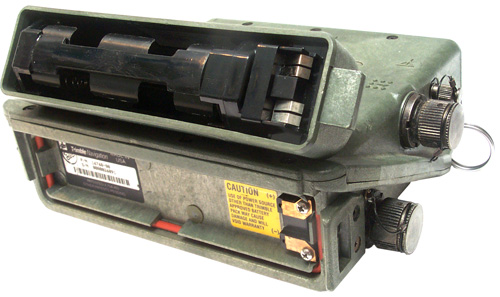
Dis-assembly
Remove 13 each screws with a 5/64" hex driver that are around the diagonal part line. and wiggle carefully apart since there is a 2x8 pin header connecting the two halves. I have heard that some receivers have a ribbon or flex cable making the connection.
Construction
One part is the bottom back. It has the battery connection and inside a switching power supply. The Front Top contains the control panel and built-in antenna and one the sides any I/O connectors that may be needed.
Both the power supply and the top Printed Circuit Boards in the 14992-20 have a number of parts that are not installed. This is a common practice where a manufacturer builds a single design for the PCB and stuffs the board different ways to make different models.
Bottom of Case
Power Supply Board
Is a switching mode power supply. Heat sink to bottom of case. Provides 5.0 VDC to power receiver.
Rx Model
Rx s/n
P/S Assy #
Problem Description
14992-20
3102A00532
12534-00 Rev 2 PCB Ground input trace burned out, R12 blown open
14992-20 3051A00116 12534-00 Rev 2
16768-80 0080026091
17410- Rev A
CR6 shorted
Parts
U1 - MC33063 - Switching Mode Power Supply controller. There are maybe a couple of dozen parts surrounding this chip resistors, caps, diodes and transistors. Looks like an expensive SMPS.
U2 -Philips HEF4011BT - CMOS positive quadruple 2 input NAND
U3 - Motorola 14013B - CMOS Dual type-D flip-flop
U4 - 14 pin IC not installed. What's it for?
Q2 - not installed and a jumper is there, maybe emitter to base?
Dead Power Supplies
R12 is connected between the Source of Q1 and ground. A larger problem is CR9 (1N4934) Fast Recovery Rectifier 100 Volts and 1 Amp rating. It's connected across the input to the power supply where it is normally out of the circuit, but if the input polarity is reversed then it dies and these other problems occur.
This blown R12 resistor was easy to see by just looking. It's marked 0.2 Ohms and maybe 3 Watts.
Trimble 14992-81 Pathfinder Basic XL Power Supply Crud
Memory Battery vented fumes that attacked the power supply and . . more disassembly needed.
I think once the battery vented it's fluids the receiver was still being used and the heatsink on the power supply somehow caused the white crud to form.
Trimble 14992-81 PathfinderBasic with very leaky battery
Black color battery marked: L-104 FCE 04 95
The bottom view of the back of the analog OCB shows an added diode and added resistor.
Back panel has label "Basic XL Upgrade, p/n 29445-00"
This one has different traces burned and on the other side the J1 header plastic is melted.
This means if you apply reverse polarity at the Battery Terminals you will fry the Trimpack
Diode CR9 is connected across the DC input and if reversed DC power is applied from a non fused source the board is fired.
Connectors
J1 External DC Power
- 1x5 header - has jumper on pins 4 & 5. right next to a place where a J-229 type 5 pin connector could be installed on outer case. This is where the External Power connector is installed. When the Trimpack has the external power connector and is running on batteries a special "shorting cap" is needed that does the same job as the jumper on the header pins 4 & 5.
Note - For internal battery use cap shorts all pins toghther.
Pin
Function
Note
Wire
Color
P1
A
Internal Batt Neg
Do not use
Yellow
5
B
External Ground
Orange
4
C
Internal Ground
Do not use
Brown
2
D
External Power
+9 to +32 Volts
Red
3
E
Internal Battery Negative
Do not use
Black
1
For External power only connect to pins B and D.
J2 - Power Supply to Receiver
2x8 header that connects to J41 on the digital board
Pin 1 is on the row closest to the printed circuit board and to L2.
The row closest to the PCB is 1, 3, 5, 7, 9, 11, 13, 15 and the even numbers are the other row with pin 2 next to pin 1. This is the normal ribbon cable type header.
All the power supplies are very similar. The early assy 12534-00 has provision for Q2 but a single two ended jumper wire with a ferrite bead is installed there. The 17410- assy has the jumper with ferrite marked on the PCB as B1 (Bead One).
Pin
Function
1, 3, 6, 8, 10
Ground
2, 4, 12, 14
+ 5 VDC
5
PS on/off control 7
- 8 VDC raw
11 Reduced Input voltage 9, 13, 15
control inputs
16
batt detect output 16768-20 ps 17410-
not 12534-00
J3 - Screw connecting to the battery negative terminal
J4 - Screw connecting to the battery positive terminal
5408193 Active circuit filter for reducing conducted radiation from a load back to, Eric B. Rodal (Trimble), Apr 18, 1995 - method of reducing Switching Power Supply noise, but not used in Trimpack
Note Q1 is the MOSFET that switches the input voltage on the transformer primary. It's very sensitive to everything and when it degrades the negative supply voltage changes causing problems in seeing the LCD. A test is to use a lab CVCC power supply set for 13 Volts and 5 ma applied across CR3 (12 Volt Zener diode). You should see the Zener voltage, but if you see less measure the source to drain voltage on the MOSFET while CR3 is biased and you may see that it's voltage is being pulled down by a defective Q1. This can happen while Q1 works well enough to supply the +5 output. It's also very static sensitive. 2 Apr 2009 - I have 10 of the IRL530NPBF on order so well see how they work shortly.
Top of Case
The CPU is a Motorola MC68HC000. There are only two static RAM chips installed, but it looks like you could have 8 installed. This might be used for increasing the number of way points.
Digital Board
Remove 8 each Philips #1 screws to free board. carefully lift it up off the the two headers that connect it to the analog board below.
Parts
U1 - MC68HC000FN10 32 bit CPU the 10 suffix may mean a 10 MHz clock rate
U5 & U9 - HM62256LFP-10 Hitachi 32 k x 8 bit Static RAM chips, the -10 may mean 100 ns access time
U2, U3, U4, U6, U7 & U8 - pads for more RAM chips Maybe JU1, JU2, JU3 & JU4 are related to the RAM option?
U10, U11, U12, U13 appear to the the ROM or EPROM chips with the code for the 68000 CPU. They are 28 pin chips, but are in 32 pin sockets. p/n 17246-01, -02, -03 and -04
27C512 (28 pin) or 29C04 (32 pin)U15 - DS1231-20 - Low Battery Voltage detector
U16 - DS1221S - keeps data valid as static CMOS RAMS are powered up and down, pins 13, 12, 11 & 10 go the Chip Enable on the RAM chips.
U17- TNL 13816 - probably Trimble custom gate array IC
U18 is the same p/n as U17. Might be the Auxillary Output Chip that does the P-code processing or might be another 3 channels????
U20 - OKI M6242B - real time clock with date, time and alarm functions always powered either external or by BAT1
BAT1 - Tadiran TL-5104 3.6 Volt AA size with wire leads
Connectors
J3 - 2x20 header socket connects the the analog board. Pins 17 & 19 are one polarity power from J41 and 18 & 20 the other polarity from J41
P2 - 2x4 header socket connecting to the analog board. Physically close to the CPU and connected to it.
J41 - 2x8 header socket connecting t the power supply board
Under the top digital board with the CPU and related circuitry is what appears to be an analog/RF board that has a couple of daughter boards and these have granddaughter boards. U8 is used to process the fill key.
Analog RF Board
Remove 8 each hex spacers with 3/16" nut driver. Lift up to disconnect the 2x12 header connecting to the panel PCB. Unplug the INT and EXT coax antenna cables.
Parts
CR5 - LM335 - analog output Precision Temperature Sensor. Feeds U5 A/D converter
Q5 - 2N2907 near the EXT antenna connector, maybe related to sensing or powering the external antenna.
U1 & U2 -not installed 16 pin surface mount parts. very close to J3 connecting to the front panel.
U4 - 74HC574 - Dual type-D Flip-Flop
U3 - XR88C681CJ - Dual UART & 8-bit I/O port- This is to communicate with the panel and for external computer I/O.
U5 - ADC0808FN - 8 channel MUX + 8 bit Analog to Digital converter. 100 microsecond conversion time, easy interface to 8 bit micro controllers.
U6 - SA5230 - low voltage op amp on the INT antenna side.
- Sympathizer operation
- IF module
- Antenna Power Supply Feeds
- Internal Temperature
- Display Temperature
U7 - TI026B - ? part of the EXT antenna circuitry
U8 - Not Installed 44 pin IC PPS-SM socket
U11 -74HC04 - High speed CMOS Hex Inverter part of the EXT antenna circuitry
Y1 - NDK 16.368 MHz oscillator in a can. J7 is what looks like the hold pattern for an SMA or OCX jack maybe to measure the oscillator output. Or maybe to be used for an optional larger oscillator. Probably the clock for the 68HC000.
Connectors
P1 - Not installed, 9 pin header with pin #4 not used, polarize the connector, Near uninstalled U8
J1 - 2x20 header connection to J3 on digital board
J2 - 2x4 header mates to P2 on digital board (P2 is near the 68HC000)
J3 - 2x12 header socket connects to panel P3 header
J4 - 1x6 header with pin #2 removed. right next to U8 which is missing on the 14992-20. maybe goes to the key load connector when it's used.
Function
The INT and EXT antenna inputs seem to both be combined rather than switched and go to FL1, a bandpass filter. From there to U10 maybe a MMIC amplifier then to an Image Rejection Mixer daughter board made from microwave quality double sided PCB material. On either side of the coupler daughter board there are two more daughter boards. One is the half LO synthesizer that uses the OCXO for it's reference frequency and the other daughter board is the IF strip with the hard limiter operating with a 4.092 MHz input from the IR mixer.
The TNL16239 Synth PCB has a metal shield can over the synth IC.
The IF daughter board has a lot of ground plane on one side and an LT1016 Ultra fast precision 10 ns comparator, SA604AS low power 45 MHz F0, 25 MHz BW FM IF, and LM2904 dual op amp.
Behind the panel is another board to support the panel functions.
Panel Board
Parts
U1, U3, U3, U4 - OKI M5839B - maybe LCD related memory?
U5 - HD44780 - the standard alphanumeric LCD controller chip
U6 - LM2904M -low power dual op amp - Probably related to the display temperature measurement that different from the internal temperature measurement.
Connectors
P3 2x12 header connects to analog board J3 socket. This is a right angle header, so you can not remove the panel without first removing the analog board.
There are 5 holes in line, like would be used for a 5 pin header next to the panel switches L, R, INC, DEC, maybe for testing them?
Startup
After separating all the boards for the photos and changing the UTC offset to LOC=UTC-7 for California and Daylight savings time, it took about 1 hour and 8 minutes of " Tracking 0 SV's" until it started tracking again.
I have seen the # of SV's go up to 8 outside in the open. After the receiver has sat in the same position for awhile and is tracking well, if it is moved, even a few feet it seems to sense the change and the # of SV.s drops and then in time comes back. So I'm going to try again to get the EXT antenna connection to work by leaving the receiver in EXT ant mode for a few hours.
This appears to be newer than any of the above receivers in that it is a 6 channel, rather than a 3 channel receiver. The 19437-60 appears to be a civilian receiver based on the use of a plastic Conxall connector for the Computer I/O instead of the military U-229 type connector.
 |
 |
Part Number Table
Description # Chan
Color
Trimble p/n NSN Con1
FW
Comment
TransPak II
6 L1
Black
Org ltr
19437-60 n.a.
A X
4.10
This is a civilian GPS receiver.
Pathfinder
6 L1 Black
14992-60
Comes in suitcase with ext antenna, yellow bag
TransPak II
6 L1
Black
Org ltr
14992-70
A, I
4.10
Op & Maint manual
na
na
18090 Rev C
6.5 x 4.5" 75 pages, June 1992
Addendum
na
na
19677 Rev. A
6.5 x 4.5" 12 pages, Jan 1992
1 Connectors A = Antenna, P = Power, K = Key Load, I = I/O
Mating connector to make a Conaxll cable p/n 6282-7SG-3DC available from Electroshield
There is a plastic "CXA" 7 pin connector just behind the Antenna connector, where the computer I/O connector is on other Trimpack receivers. Don't yet have a pin out for this connector, but it's a computer I/O connector, but not the standard military U-229 type. The Manual Addendum says "TransPak II GPS Personal Navigator with I/O". The manual is dated 1992. TransPak IIs shipped in February 1992 and later have a six-channel GPS receiver. The 6 channel version is part number 19437-60.
After connecting to a clip on vehicle power adapter and my house antenna using the two extra in-line DBS GPS amps, this receiver was tracking in less than a minute. The eBay seller had used it prior to the auction and so the almanac was not that old.
In the Status (STS) menu, line 3 showed calculating satellite visibility for a number of minutes, then it changed to calculating window, cycle nnn, where nnn increments up from one. Then "Full 24hour Coverage". Window was a term used when there was not a full constellation of GPS satellites or when you are very far North or South. The "Window" will forecast those times when you will have 4 or more satellites visible.
Menus
On the Set Up page if in line 1 you choose SEA mode then the last entry in line 3 can be changed from OFF to AV2 through AV10 which will average 2 through 10 fixes and display the result. This does not change the computer data. But you can not average a lot of positions like in the Trimpack above.
On the Set Up page line 3 if you select NMEA then press "R>" you can turn on or off SETMSG, this allows turning on or off the following NMEA sentences. These have the check sun turned on.
APB - Autopilot format B ->
$GPAPB,A,A,0.00,L,N,V,,002,M,100,002,M,002,M*40
BWC - Bearing & Distance to Destination waypoint ->
$GPBWC,144800.63,0000.00,N,04500.00,E,018,T,002,M,2432.1,N,100*2C
GGA - GPS Position ->
$GPGGA,144801.67,3911.41,N,12309.84,W,1,3,04,268,M,-24,M,*6F
GLL - Lat & Lon ->
$GPGLL,3911.41,N,12309.84,W,144802.42,A*11
VTG - Actual Track & Ground Speed ->
$GPVTG,012,T,356,M,0.02,N,0.03,K*4C
XTE - Cross Track Error
$GPXTE,A,A,0.00,L,N,V,,002,M,100,002,M,002,M*40
Check Sum - check sum
The TIME menu has:
line 1: DDMMMYY HH:MM:SS This is the full current Date & Time
line 2: ETA ******** Estimated Time of Arrival to the selected Way Point
line 3: TTG ******** Time To Go = time left until the way point
line 4: LAST FIX HH:MM:SS If the receiver is working from an older fix it lets you know
Two Computer I/O protocols:
- ASCII - may be very limited based on the Operation & maintenance Guide
Operation & Maintenance Guide for TransPakII. available from NEI.
- NEMA 0183 (APB, BWC, GGA, GLL, VTG, XTE
RS-422, 4800 8N1.
Function Switch positions: OFF, POS, NAV, TIME, DIST, WPT, STS, SET UP
Computer I/O
The NEI-16844 Data Cable is terminated with a DB-9(f) connector that plugs directly onto a computer RS-232 Serial port. It works for both receiving and sending commands as is. There is a difference between the pin out of this cable in terms of Tx- and Tx+, Rx- and Rx+ and the cable for the Trimpack above that I can't explain. Both cables work or their respective receivers.
Note1: there are no flow control jumpers, so the controller needs to be set for no flow control.
TransPakII Pin
Description
NEI-16844
cable DB-9(f)
1 Rx-
3 TXD
2
Tx-1
2 RXD
3
Tx+
nc
4
Rx+
nc
5
HQSEC2
9
6
GND
5 Gnd
7
Rxda3
nc
To see the data in Hyper Terminal:
Note2 There is nothing in the manual about pin 5, it may be Have Quick 1 PPS or HQ data, need to check with scope.
- ASCII 9600 8O1 no flow control
- NMEA 4800 8N1 no flow control
Note3 There is nothing in the manual about pin 7 Rxda, it may be an RTCM 104 DGPS data input

The P code is on both the L1 and L2 frequencies. . That's because of how the RF front end works as described in patent 4754465. SAGR, Centurion and Trimpack III are all names for these receivers.
Auxiliary output chip (AOC)
This is the chip that processes the Anti-Spoof (AS) code.
PPS Security Modules (PPS-SM)
This is the capability to process the Selective Availability signal to get a more accurate position.
SAGR
AN/ASN-169 Standalone Air GPS Receiver is an upgraded SLGR by Trimble. It looks very similar to the SLGR.
Part Number Table
Description # Chan
Color
Trimble p/n NSN Con1
FW
Comment
Centurion 6 L1P
18154-00
A P K
same as SAGR AN/ASN-169
Trimpack III
Standard Positioning Service
6 L1
23365-00
A P K
Firmware does not support Key Load
TB 5826-314-10
SAGR, AN/ASN-169 6 L1P Black 20636-00-IN 5826-01-414-4147 A P K
seems to be two different NSN for the same p/n?
SAGR, AN/ASN-169 6 L1P Black 20636-00-IN 6605-01-383-3377 A P K
SAGR - Antenna L1/L2 na
Black
5985-01-422-471? A
1 Connectors A = Antenna, P = Power, K = Key Load, I = I/O
Key Load Connector
This is a 6 pin version of the U-229 connector that's often used on military radios like the SINCGARS for Key Loading and/or AUDIO functions.
Pin
Function
Description
A
+5 V Signal Referenced to ETD
key load ground
B
ETD Installed
C
Request
D
Data
E
Clock
F
Spare
|
Ruggedized PPS capable portable receiver Trimble's Centurion™ is the most robust and environmentally rugged military P(Y) code GPS receiver on the market today. The system is based on the Trimpack™, Trimble's military receiver that demonstrated excellent field reliability in real combat situations during Desert Storm. It provides military grade GPS navigation for both ground and air-based military operations. The receiver is exceptionally easy to use and includes features such as rotating control knobs that pilots and drivers find easier to operate than push buttons. Its internal reference oscillator was specifically designed for the high-vibration environments of helicopters and armored vehicles. The dual frequency capability provides additional protection from jamming. The US Army Communications Electronics Command (CECOM) and other NATO countries have selected Centurion for installation in helicopters.
|
![Trimble Centurion
p/n 18154-00 Model:20636-00[SM] GPS Receiver](Images/1815400Frnts.jpg)
![Trimble Centurion
p/n 18154-00 Model:20636-00[SM] GPS Receiver](Images/1815400Ins.jpg)
"This receiver has two primary capabilities that the PLGR does not have.  One is the ability to operate in either PPS-
tracking mode, or in SPS-mode and, with another Trimble GPS unit such as the Pathfinder, produce differentially-corrected data.
The other capability is that features and attributes can be coded and stored in the Centurion as part of the fieldwork."
The packaging and most accessories for all these GPS receivers is common.
Antenna Connector
Antenna Connector is an SMA(f). It has 5 VDC coming out to both power an external antenna and sense that there is an external antenna connected. It may be that the external antenna needs draw current in a specified range, if the current is below some threshold the receiver senses not external antenna and uses it's built in antenna. If the current is above some value the receiver uses switches to EXTernal antenna mode, but does not use the external signal. I'm guessing this because of strange behavior I have seen.
14992-20 Antenna Voltage vs Current
Load
Ohms
Voltage
Current
ma
open
5.09
0
470
4.99
10.6
220
4.9
22.2
100
4.6
46
47
3.8
80.8
Antennas
The Trimpack line needs an active external antenna with about 41 dB of preamp gain, but most active GPS antennas have about 20 dB gain. That means they are short 20 dB (10 times voltage) the needed gain and therefore will NOT work on the Trimpacks.
You either need one of the antennas made for the Trimpacks or use an amplifier between the antenna and the Trimpack.
The Trimpack is specified to supply +5 Volts on the center conductor at up to 80 ma, but I think that if the antenna actually pulls 80 ma it will degrade the receiver, so less than 80 ma is desirable.
Some current needs to be drawn from the receiver so it can sense that an external antenna is connected. Then power is removed from the internal antenna. The Status page will display which antenna is being used.
For more on GPS antennas see the Antenna section of the DAGR web page.
Antenna Related Part Number Table
Description
Trimble p/n
Comment
External Ant for 16768-xx
4 x 3.75 x 0.5" SMA(f)
thru hole mounting
12038-00 80 ma 3.5 - 4.5 VDC
12765-00 cable
1565 - 1585 MHz RHCP
Gain: 5 dBi (max) @ 0 deg
Gain: 0 dBi (min) @ 75 - 85 deg
axial ratio: 3 dB @ 85 deg
Ellipticity: 3 dB (max)
Preamp
1565 - 1585 MHz
42 - 50 dB gain
2.0:1 max VSWR
80 ma DC (3.5 - 4.5 VDC)
6 meter Antenna Cable
12765-00
Aircraft Install kit
14726-30
marine antenna
white
14825-02
not tested labeled "Transpak" RG-6 coax
16046-10
Kit: 22020-00, 10 m cable, ht rod, pouch
SLGR- Antenna Aircraft Green 16248-40
Pathfinder White 16741-00
3/4" high Aircraft Antenna White
16248-10
Antenna, Type-N(f) connectorblack
____
Olive
drab17572-00 probably the 12038-00 ant
on the
12960-00 surface mount adapter
(actually is a 16248-40 ant)
22020-00
compact L1/L2 no gnd plane
23033-00
compact L1/L2 with gnd plane L1/L2 External Antenna
22433-20
23903-00
Perm Ref Stn L1/L2 Geodetic (HD ver of 23033-00) Mag Mount External Antenna
28367-40
Military Antenna 17572-00
This antenna does work with the Trimpacks.
Inside the case is a 16240-00 antenna. The case holds the thin antenna and provides a Type-N(f) connector. The bottom of the 17572-00 can be surface mounted to a vehicle or be screwed onto a modern surveying tripod that has a 5/8-11 male thread (or you can use a tripod adapter that screws onto your 3.5-8 male thread and has the 5/8-11 male thread on top.
There four 0.275" dia. mounting holes on a 4.25" x 1.75" pattern in addition to the 5/8-11 female thread for a surveying tripod on the bottom. It's interesting that this antenna has the survey tripod thread, the implication is that it has a well controlled phase center that's suitable for carrier phase surveying. If you have any info on this please let me know.
Note by holding a light at one of the slots you can see inside, that's how I read the actual antenna p/n. No need to take it apart and take a chance of breaking the small coax/
28367-40 Mag Mount Antenna - Does NOT work
When connected to the 16768-20 receiver the Status line that normally says GPS OK now says Receiver fault (16). This is the fault that you get when the Ext Antenna SMA(f) jack is shorted. The receiver does NOT switch to the external antenna and continues to operate from the internal antenna, but with the heavy current draw it does not work as well as with the 28367-40 disconnected.comes with 16 1/2 foot of 1/8" diameter coax with an SMA(m) connector that mates to the Trimpack. Is a small mag mount GPS antenna made by Trimble. This antenna pulls 82 mA of current. The spec for the Trimpack is 80 ma.
When connected to the 14992-20 the receiver shows EXTernal antenna and does track some satellites, but not as many as with the internal antenna. Maybe this antenna has a little less than the needed 41 dB gain.
Tried three different antennas on both receivers. All three work OK on the 14992-20 and all three generate the Receiver fault (16) message on the 16768-20 receiver. This must be due to a subtle difference in the threshold for determining when the external antenna is short.
It's not clear to me if this antenna should work and these are out of spec. or if this antenna should not work.\
V
ma
Ohms
d Ohms
1
5
200
-
2
11
181
166
3
14
214
200
4
18
222
250
5
22
227
250
6
26
231
250
16741-00 Small Dome Antenna
This came in it's own yellow carry case as part of a Pathfinder system.
It has a Type-N jack.
The bottom center mounting hole is threaded for a pipe (not sure what size) and it has a thread reduced with 5/8-11 threads on the inside. Into those threads is screwed the mag mount. All making for numerous mounting options.
The large washer allows this antenna to be used with a 3 1/2"x 8tpi tripod head.
Since it works with the pathfinder it also will work with the Trimpacks and most any GPS receiver.
 |
 |
| Trimble
p/n: 14177-00 GPS Antenna The phase center is 2.6" above the bottom surface. (the 4000 SSI antenna is p/n 24840-21, SSI puts out 10VDC) (the 4000 SST antenna is p/n: 14532-00) (the GEOID w/Ground Plane is p/n: 23033-00) (the GDOIC w/o GP is p/n: 22020-00) All these antennas are rated for 7 - 28 VDC, so why the caution? |
CAUTION:
4000ST/SST Antenna Use with 4000ST/SST only. Connection to other equipment may destroy antenna and will void warranty. Do not cunnect to 4000SL/SX/SD/SLD or other manufactures receivers. On another face is the mechanical drawing showning the phase center and "L1" |
21423-00 white hockey puck
The Trimble Model 21423-00 white hockey puck active antenna (used with the SV6 receiver) draws about 22 ma. By using a rubber band on a BNC-T connector and a BNC(f) to SMA(m) adapter you can get the Trimpack to think it's powering an active GPS antenna without overloading the power supply like a 50 Ohm load does, but the receiver still does not Track any sats, why?3964834 Diagonally fed electric microstrip dipole antenna, Cyril M. Kaloi (U.S. Navy licensed to Trimble for the 21423-00 white hockey puck active antenna), Oct 5, 1976, 343/700MS ; 343/830 -
Ans.: The Trimpack needs 41 dB gain in the antenna which is more than most active antennas provide. This makes sense since the Garmin III+ and Motorola VP+ GPS receivers are designed to work with a passive antenna connected directly to the receiver. The active antennas offered by Garmin and Motorola have a small amount of gain (typically < 20 dB) to make up for short cable runs. The requirement for 41 dB of gain after the antenna, excluding any cable loss, is a lot different from what my other GPS receivers need.11 Aug. 2003 - By adding two each Radio Shack 16-1156 In-Line DBS Satellite amplifiers and using the Wall wart power supply and Bias-T from a Radio Shack 15-1170 In-Line TV amplifier, plus a BNC-T connector next to the Trimpack with a 100 Ohm resistor to get the Trimpack to go into external antenna mode, the receiver is tracking between 5 and 7 satellites. The Wall wart I'm using puts out about 13 volts when driving a single satellite in-line amp, but only 10 volts when driving two of them. Need a supply with more current capability, and that should add more gain. I think this is needed because the Garmin III+ is tracking more satellites, and the Trimpack can track up to 8 satellites.
This was a mistake! The roof top antenna was a Motorola hockey puck that wants to see 5 volts and it died when 13 volts was applied. This happened because the 4-way divider has two ports that have a DC connection to the antenna and two that are DC isolated, and I did the above experiments on the port with the DC connection.
Other GPS Antenna patents by Cyril M. Kaloi (U.S. Navy)
3594810 TRIANGLE-LOOP ANTENNA, 220-260, 1435-1534, 2200-2290 MHz triple band blade ant.
3978488 Offset fed electric microstrip dipole antenna
3972050 End fed electric microstrip quadrupole antenna
3947850 Notch fed electric microstrip dipole antenna
3972049 Asymmetrically fed electric microstrip dipole antenna
3978487 Coupled fed electric microstrip dipole antenna
4074270 Multiple frequency microstrip antenna assembly
4095227 Asymmetrically fed magnetic microstrip dipole antenna
4078237 Offset FED magnetic microstrip dipole antenna
4067016 Dual notched/diagonally fed electric microstrip dipole antennas
4083046 Electric monomicrostrip dipole antennas
4051478 Notched/diagonally fed electric microstrip antenna
4069483 Coupled fed magnetic microstrip dipole antenna
4072951 Notch fed twin electric micro-strip dipole antennas
4040060 Notch fed magnetic microstrip dipole antenna with shorting pins
4197544 Windowed dual ground plane microstrip antennas
4125839 Dual diagonally fed electric microstrip dipole antennas
4125838 Dual asymmetrically fed electric microstrip dipole antennas
4125837 Dual notch fed electric microstrip dipole antennas
4155089 Notched/diagonally fed twin electric microstrip dipole antennas
4157548 Offset fed twin electric microstrip dipole antennas
4151531 Asymmetrically fed twin electric microstrip dipole antennas
4151530 End fed twin electric microstrip dipole antennas
4151532 Diagonally fed twin electric microstrip dipole antennas
4117489 Corner fed electric microstrip dipole antenna
4170012 Corner fed electric microstrip dipole antenna
4163236 Reactively loaded corner fed electric microstrip dipole antennas
4291311 Dual ground plane microstrip antennas
4291312 Dual ground plane coplanar fed microstrip antennas
4326203 Corner fed electric non rectangular microstrip dipole antennas
4347517 Microstrip backfire antenna
4356492 Multi-band single-feed microstrip antenna system
4370657 Electrically end coupled parasitic microstrip antennas
4401988 Coupled multilayer microstrip antenna
4415900 Cavity/microstrip multi-mode antenna
5389937 Wedge feed system for wideband operation of microstrip antennas
Radio Shack GPS Amplifier
Using the two Radio Shack Satellite in-line amplifiers and the external power connection for DC, the AN/PSN-10 has been running for a number of days and whenever I check the number of SVs being tracked it's always 3 or more, but rarely more than 7, even when the Garmin III+ is tracking 12 satellites. The input to the two series connected amplifiers is from my house 4-way GPS power divider.
The In-Line satellite amplifier is an RCA D903 and is specified for 15 to 18 dB gain from 950 to 2050 MHz. I checked it at 0 to 500 MHz and saw only loss. The Input center conductor is tied to the output center conductor for DC so it will pass the DC bias through so multiple amplifiers and/or an antenna mounted amplifier can be driven through the coax. The "TV" side of the Bias-T is DC blocked so that no DC is applied or taken from the Trimpack, hence the need for a resistor in that spot.
Current draw for the 2 DBS amplifiers is:
V
ma
Commercial Delta Microwave Model L5008 L Band Amplifier
Attaching a commercial 50 dB gain L band (1 - 2 Ghz) amplifier to the output of the house 4-way GPS divider and directly into the PSN-10 works. The AN/PSN-10 is tracking 6 satellites and the Garmin III+ shows 6 sats. The interesting thing is that the STS page shows INT antenna. This is because the commercial amplifier has a DC blocked RF output and so does not draw any current from the Trimpack. BUT, I think the antenna input circuit is a power combiner, NOT a switch, so the strong signal from the external antenna jack is going into the receiver and being used. The internal antenna is being powered but it can only pick up a couple of sats inside my house. I confirmed this by turning off the DC power to the L band amplifier. Then the PSN-10 only tracks 2 sats.
I think that all the Trimpacks work this way, but have not tested all of them yet.
About 2 1/8" diameter and 1/2" thick with a 1 meter long coax terminated with a right angle SMA(m) connector. There are 4 each 6-23 tapped holes on a 1.3" square pattern on the bottom.
Sensor Systems S67-1575-58 Passive GPS Antenna
This antenna will NOT work with Trimpack receivers.
However it works well as a transmitting antenna when connected to the output of a high gain L-band amplifier. Without using a power divider a number of GPS receivers can all be operational receiving the GPS signal from the antenna on my roof by means of amplification and reradiation.
19 Oct 2003 - With the AN/PSN-10 and TransPakII receivers sitting side by side (but separated by about 6" which seems to help) the TransPakII is much more sensitive. They both are getting the signal transmitted from the Sensor Systems passive antenna. For example the TransPakII is receiving 6 SV's while the AN/PSN-10 only is tracking 3 SV's. Tried reversing their positions to see if there was a hot spot from the Sensor Systems antenna, but the number of SV's tracked stayed with the receiver not the position. It's too bad that the TransPakII does not have the long averaging function, it only has a 10 second average when in SEA mode to average a ships position in swells..
Gilsson Technologies - might make an antenna that would work with the Trimpack, but the case I know about it isn't working.
14825-02 Trimble Transpak GPS antenna
The eBay ad mentions an RG-7 coax connector and this looks like a marine antenna.
The label in the photo says:
Antenna, Transpak GPS
All the Trimpack type receivers have a 3.6 Volt Lithium battery soldered to their digital Printed Circuit Board. There is a Dallas chip that makes the RAM memory into a non volatile memory. All of these batteries I've seen have been good. It's now 2003 and some of these receivers were built in 1990. The SV6 receivers have provision for an external back up battery.
It can take more than 12.5 minutes for a cold start because the receiver needs to download the complete navigation message from one satellite. This can only be done after the receiver finds a satellite. This message from one satellite has the almanac data for all the satellites so the receiver knows which satellites are in view. Next the receiver needs to download the ephemeris from each satellite in view and then lock onto that satellite.
If the back up battery fails then every time the main battery is replaced the receiver will do a cold start. But when the back up battery is working the receiver will do a hot or warm start and will acquire satellites within a few seconds of power on. The exception to this is if the receiver is moved more than 100 km while turned off, then it will be "lost" at power up and do a cold start.
Hardware
Computer Interface Connector
This is a 6 pin version of the U-229 connector like is used on most military radios for the AUDIO interface. Use a GC-283 plug.
It supports RS-422, but can be used for RS-232 on most modern computers as shown below. Notice that there are no flow control signals so either you need to configure your computer port for no flow control or jumper RTS to CTS so the computer sees hardware flow control.
I/O Cable
An official RS-422 to whatever level converter can be used since the Trimpacks use a 4 wire (TX+, TX-, RX+, RX-) interface, BUT you can also use a passive cable on most computers. Here's what works for me:
1 I placed a resistor and diode in the connector shell of the DB-9 connector to limit the +12 Volt possible with RS-232 down to near +5 volts going into the Trimpack. The first circuit limited the voltage swing to +4.3 V for high and 0.28 V for low and the Trimpack would not respond. This circuit limits the swing to +4.8 V and -0.59 Volts and the Trimpack works fine.
Trimpack
Pin
Function
Computer
DB-9(f) Plug
A
RX+ Circuit see1 below 3 Tx
B
TX+
2 Rx
C
TX- no connection
D
RX- 5 Gnd
E
1 PPS out
1 DCD2
F
Gnd 5 Gnd
From the DB-9(f) Tx pin 3 place a 100 Ohm resistor in series to Pin A on the Trimpack mating connector.
Place a 5.1 Volt Zener diode with it's cathode band from the wire from Pin A to DB-9 pin 5 (ground).
I was told by a Trimble employee that the Trimpack receivers do track carrier phase as part of the velocity determination algorithm. But carrier phase is not available in any of the software data packets.
Software
Trimble has an ftp web page where you can download software for a number of their products, including a general purpose program called Trimble Studio. Studio works with both TSIP and NEMA formats and so can be used with other brands of GPS receivers.
Protocols
Different Models of receiver support different I/O protocols.
Name
hw
Model
I/O connector
TSIP
TIPY
TAIP
NMEA
ASCII
Track-2
9600
9600
4800
4800
9600
9600
8O1
8N1?
8N1
8N1
8N1
8O1
Transpak
RS-422
14992-20
none
-
- - - - Trimpak
RS-422
16768-20 AN/PSN-10
U-229
YES
-
-
-
-
YES
TranspakII
RS-422
19437-60 Conxall
?
?
YES
YES
-
Centurion
RS-422
18154-00 U-229 ->
YES
-
?
?
?
SV6
RS-232
21589-00
2 ea. DB-9(f)
YES
-
YES
YES
-
-
Placer
RS-232
18694-00
see below
-
-
YES
-
-
-
LabVIEW Driver
Now have a LabVIEW (5.1) instrument driver that reads all TSIP packets and places them into an array. Each row of the array is dedicated to a packet number (0 to 255 corresponding to 00h to FFh). Individual VIs will be written to work with each documented packet. As of 28 Aug. 2003 the following packets have been done:
35 Set/Request I/O Options - XYZ, Lat-Lon-Alt, Single or Double precision, etc.
40 Almanac Data for a Satellite
41 GPS Time, Week # and UTC Offset
42 Single Precision Position Fix in XYZ ECEF format
43 Velocity Fix, XYZ EDEF format
44 Tracking Mode and the SV #s of the 4 sats being used
46 Health of Trimpack
47 Signal strength
48 GPS System Message (22 ASCII byte message)
49 Health of all 32 Satellites
4A Single Precision LLA Fix
4B GPS Receiver ID
5B Ephemeris Data for one Satellite
5C Satellite sig srt, tracking mode, Az, El
6D Tracking mode and a list of all SVs being used
84 Double Precision Lon Lat Alt Position Fix (8 byte radian number for Lon and Lat, way more precise then Single precision on LCD and can be averaged.)
Mystery Cable
This came with a bunch of Trimble stuff.
MC329G2 (U-229 type) 6 pin connector to DB-9f.
Marked: 24666 REV A1, DCA 9526
Trimble molded into DB-9 housing.
Pinout
U-229
Function
U-229 Pin
DB-9
Function
DB-9
Gnd
A
TxD
3
headphones
B
RxD
2
PTT
C
Mike
D
Gnd
5
tbd
E
tbd
F
Gnd
5
This may be a key load cable. Note DB-9 pin 5 is ground and is connected to pin D. This wiring when combined with a 0-5V implementation of the RS-232 protocol would result in an inverted polarity keying signal. See U-229 Pin Out - Fill for more info.
GPS Week Rollover Bug
Note: I received an email pointing out that there's a GPS week rollover bug in the ASCII protocol and display, but not the binary protocol.
Since 23 NOV 2006 dates displayed on old Trimble GPS receivers (such as Trimpack, Transpak, Scout and Explorer) have been wrong.This seems to be a delayed rollover problem since dates have jumped back exactly 1024 weeks. It looks like Trimble avoided AUG 1999 rollover problems by subtracting 7 years from the internal receiver times but still used modulo1024 week arithmetic. At least 7 different models are affected in the same way so it looks like Trimble has been copying old software code from one model to the next without looking at it very closely.Position and navigation have not been affected since they only depend on the time-of-week.The binary computer protocols are not affected since they use GPS week numbers and seconds-of-week but the ASCII protocols give wrong dates.
April 2009 - The few receivers I've been working with do not show the month or year at all, just the Day of Week and Time which have been correct. Haven't looked at the Computer port data.
Mounting
13214-00 Trimpack Vehicle Mount
Can tip left and right, tip front to back using a wrench.Can rotate using the lever to lock position. So a driver or passenger could easily point the front panel. The LCD in all the Trimpacks I've seen are best viewed straight on, not from above and not from below.
Power
Rear Attached Battery or Adapter
All of these Trimpack family GPS receivers use the same clip on rear battery pack. This can be one of a number of battery packs or a vehicle cigarette lighter DC adapter. The voltage must be in the range of 9 Volts minimum to 32 Volts maximum.
It can not be 6 Volts. Using a BA-5800, which fits the small battery holder does not work. The Trimpack gives a low battery error message and shuts down.On some Trimpacks there is a yellow CAUTION label saying "Use of power sources other than Trimble approved battery packs may cause damage and will void warranty." This same sticker has a "(+) symbol in the top right corner and a "(-)" symbol in the bottom right corner and that's the correct polarity to connect an external supply. So my guess is that the sticker is there to tell someone how to hookup external power to the battery terminals and at the same time say if they do it backwards the warranty is void.
This means if you apply reverse polarity you will fry the Trimpack
Diode CR9 is connected across the DC input and if reversed DC power is applied from a non fused source the board is fired.
Solution: Make up an external power cable with a reverse polarity protection circuit. Place an enhancement type MOSFET (for <15 volts) the IRF511 would work, in the ground side of the circuit (source and drain) and a 1 Meg resistor between the gate and the positive supply line. Better to clamp or attenuate the gate voltage so that when 32 volts is applied the gate stays below 10 volts. See Fig 13.5 pg 164 "Troubleshooting Analog Circuits by Bob Pease. ISBN 0-7506-9499-8
Testing
Using the diode function on a DMM should show a diode when the battery contacts are probed. The Fluke (1 ma diode test current) shows 0.502 forward drop and 1.949 (voltage limited indication of a diode reverse) for a non blown unit.
DC Power Sources
Description
Color
Trimble p/n
Comment
DC Adapter (Vehicle)
black
14934-00
Vehicle Power Adapter
22433-20
Large Battery Holder
13827-00
2 each BA-5800
Small Battery Holder
Green
13828-00
one BA-6800 or
Trimble* AA holder
Small Battery Holder Black 14902-00 "
Rechargable Battery Pack
Black
14903-00
? NiCad ? Capacity
Used with Pathfinder
NiCad Battery Pack
13829-00
battery pack
not separate cells
AA Battery Pack
18653-00
Vehicle Install kit
14726-20
* Note although the Trimble AA holder looks like a BA-5800, it is NOT the same. It connects all the AA cells in series for a nominal 12 Volt supply with Alkalines, or a nominal 10.9 Volt supply with rechargeable batteries.
This looks similar to the small battery back but it has a 12'-3' coiled cord coming out of the back center with a cigarette lighter plug. There's an TAO 3 Amp blade automotive type fuse in series with the positive lead.
14934-00 DC Power Adapter
Requires 9 - 32 VDC, 5 Watts
Batteries
These receivers run on 9 to 32 VDC and will not run on 6 VDC like is supplied by a BA-5800, but the small battery holder seems designed to hold a BA-5800. The special 8 AA cell battery holder that Trimble supplies connects all the cells in series for a nominal 12 VDC supply. They have made the contacts on their holder different from the bulls eye contacts on a BA-5800 to hopefully keep someone from using it in an application that's looking for a BA-5800.
A normal Alkaline AA cell has about 2.85 Amp hours so the 8 AA cell holder providing a nominal 12 VDC will last about 11.4 hours. The current reduces as the voltage increases indicating a switching type power supply. For input voltages of 18 and higher the current remains at 200 mA.
Inside there is a 3.6 Volt AA size battery that keeps the data alive when the main battery is removed. It is soldered into the receiver and mine measures 3.6 V, probably after about 10 years. At some point it will need to be replaced.
The STS/Battery used: number can not be accessed by the menu switches, but after running the receiver for a couple of days from an 11 Volt power supply clipped to the rear terminals, I connected the battery pack filled with freshly charged NM cells and the Battery used: number came on at :6:18. and after about an hour of use reads :7:23. So it looks like one of the A/D channels is watching battery voltage and since all of the RAM is maintained it can tell there's been a change in battery voltage at power up.
The Low Battery warning starts flashing at 7.7 Volts.
At 11 Volts input the current is 197ma, 231 ma, 245 ma and 272 ma for the backlight off, and at three levels of brightness.External Power Connector
The external DC power connector is located on the left side at the rear bottom. It is part of the Back & Bottom case half of the receiver that contains the power supply. This is a standard U-229 connector like is used on most military radios for the AUDIO interface. Use a GC-183 plug. Supply voltage should be 9 to 32 Volts.
Note the external power connector has a diode in SERIES with the pin D so if you connect reverse polarity nothing happens, i.e. no damage to the receiver like when reverse polarity is connected to the battery terminals.
Part Number Table for External Power
Description
Color
Trimble p/n
Comment
External Power Cable
12792-00 ? delta to -10?
External Power Cable
12792-10
U-229 plug
Vehicle Power Adapter
??Reverse Polarity Protection???
13825-00
Metal Box
Crowbar Over
Voltage Protect
U-229 Plug
Vehicle Install kit
14726-20
? contents
Connector Pin Out for External DC Power Connector
When operating on internal battery power the shorting cap must be installed. This is truly a cap that shorts all the pins together. Inside there is a diode between the EXT positive input (pin D) and the rest of the power supply so the shorting cap does not see the positive voltage provided by the battery pack. This diode also protects the Trimpack from reverse polarity on the EXT connector.
Pin
Function
A battery Ground
B EXT GND C not used (internal gnd) D
EXT +V, 9V to 32V E not used (battery gnd)
U-229 Type plug with Red wire going through a 1 1/2 Amp Fuse to pin "D" and a black wire going through a 1 1/2 Amp fuse to pin "B".
12792-10 External Power Cable
It's important to have a fuse in the ground lead. A number of PLGRs have been fried when they were connected to 12 Volts, but with the ground lead 12 Volts above ground, like in a military vehicle that has two12V batteries and the installer connected to the "top" battery instead of the "bottom" battery.
In my opinion Trimble got a lot of things right with the Trimpacks that Rockwell messed up on with the PLGR.
Except for the Power Supply.
14903-00 Rechargabe Battery
These were used mainly with the Pathfinder GIS receivers to provide a more economical portable power source. Uses an automotive blade type 3 Amp fuse and a coaxial DC power jack for charging.
Hardware Options
All of the Trimpacks seem to have the same printed circuit boards (maybe different version or revision numbers) but with some parts not installed. For example all the power supply PCBs have a header (J1) that could be connected to an External Power connector or have a couple of pins jumpered when there is no external power connector. They also may or may not have the parts near J2. In a similar manner the digital and analog PCBs are assembled selectivly depending on the feature set (p/n) of the final product.
P2 RF Connector between Analog and Digital Boards
P2-3 is the IF output with the PR GPS data
P2-3 is the IF output with the PR GPS data
Center frequency is 4.092 MHz which is the IF Freq.
P2-5 is the OCXO Frequency
P2-4 is a 192F0 /5 = 38.4F0 (39.28320000 MHz)
P2-6 is the OSXO Frequency
GPS Frequencies
The Trimble patent 4754465 refers to frequencies as multiples of 1.023 MHz. For example the OCXO mentioned in the patent is 48F0 although the OCXO in all the Trimpacks is 16F0 (16.368 MHz).
The GPS to Earth Link frequencies are a multiple of 10.23 Mhz (10F0), see the DAGR GPS web page for a table of them.
The patent calls for a synthesized LO at 768F0 which when doubled in the Image Reject Mixer (1536F0) and mixed with the GPS L1 frequency (1540F0) yields an IF of 4F0. The IF amplifies and hard limits the 4F0 signal to give a TTL output signal.
The SS1 daughter board appears to be a single frequency LO source. Which leaves a question of how L2 (1200F0) might be received? Maybe this is why the OCXO is 16F0 instead of 48F0.
Hopefully this can be answered after I have the test fixture build and can probe what frequencies are really being used.
Also see the DAGR GPS Signals table.
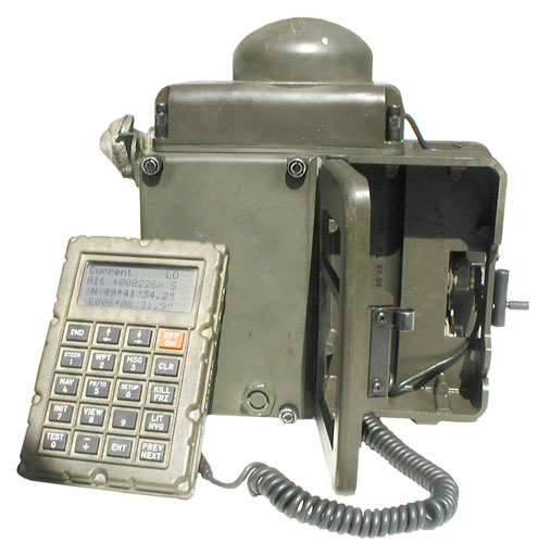 |
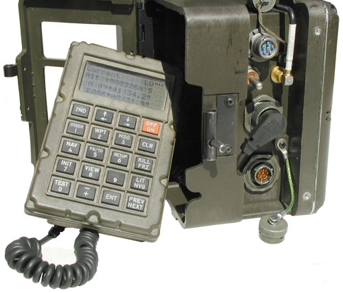 |
| PSN-9 GPS receiver "The AN/PSN-9 is a 5-channel PPS receiver that weighs about 9 pounds. It can be carried in a rucksack or over the shoulder. A small Control/Display Unit (CDU) is connected by a cable to the receiver. The antenna module can be separated from the receiver to allow remote operations. Position and velocity updates are provided once per second. The AN/VSN-9 is a vehicular version of the same receiver. The AN/VSN-9 is also installed in some small Army watercraft. There are 100 of these receivers in the Army." from FAS web page From Emdund: AN/PSN-9A . Mfr is Texas Instrument. The data plate has a blank slot for an NSN. Contract # is F04701-87-C-0054 and the Serial #
is 9024-00196 so I'm guessing it was one of a small run
made early in 1989.
Provision for Key Fill. |
|
SVeeSix
Photo - 2 each SV6 receivers, the top one is a 23198-63 (1997 date code) TAIP protocol and the bottom one is a 21589-00 (purchased from Trimble in 1990) from an evaluation kit that supports: TSIP, TAIP and NMEA.
The SVeeSix and the TANS are a box with connectors, they have no human I/O capability. The SVeeSix Trimble receiver uses the TSIP (Trimble Standard Interface Protocol) and a related manual I got from Trimble for the SVeeSix is the TANS (Trimble Advanced Navigation Sensor) manual.
TANS Trimble Advanced Navigation Sensor
The TANS is a metal box 5 x 8 x 2" with an SMA antenna jack, 3 pin power connector and a 22 pin circular mil connector for the I/O. The I/O connector can be split out into 2 I/O connectors , like are on the SVeeSix. The TANS will work with the 16248-00 Aircraft antenna, or the 12038 antenna. The TANS will connect to an off the shelf Color Display Unit (CDU). If you know what this is let me know.
The other document Trimble supplied was Appendix A "Trimpack GPS receiver, Digital Communications Interface Definition" p/n 13498, Rev D, Nov 1990. Which is the reference manual for the AN/PSN-10.
So you can see that the SV6 and TANS are also based on the same Trimble chip set as the Trimpack GPS receivers on this page. I think a lot more Trimble receivers use the same core chip set.
48000-36 GPS Receiver (aka 48000-00)
This was probably intended for use in a laptop computer, like the CF-28 Toughbook (that's how it was advertised on eBay). The blue plastic is not a connector saver but rather a shroud protecting the input coax connector and has a latching projection on the bottom to hold the mating connector. The black plastic "feet" would allow installing the receiver into four "d" holes very quickly.
This looks like the Lassen DR+GPS (Dead Reaconing) intended for vehicle location. It takes speedometer pulses and forward/reverse bit, key on/off bit and an analog gyro input (Epson XV-10, XV8100CB (3V), XV-8000CD (5V), Murata ENX-0126, Panasonic EWTS-82). Timing good to half a microsecond.
Placer 100
The Placer line of GPS receivers are designed to be used in Automotive Vehicle Location (AVL) applications. They would be connected to the 2-way radio and automatically send the vehicle location to a central dispatch office. No more "car 54 where are you". The Label says p/n 18694-00 and references the same Trimble patent number 4754465 as is on all the Trimpack type receivers. I saw somewhere that this receiver is NOT compliant with the GPS week rollover.
There is a 37 male pin connector and a type-N(f) antenna connector.
DB-37
Pwr Wires
1 = Pwr Gnd
Black wire
20 = Pwr +
Red Wire
21 = Pwr +
Red Wire
DB-25 DB-9 22 = Sig Gnd
7 = Sig Gnd
5 = Sig Gnd
23 = RS-232 TxD
3 = RD
2 = RD
24 = RS-232 RxD
2 = TD
3 = TD
25 = RTS
5 = CTS
8 = CTS
26 = CTS
4 = RTS
7 = RTS
Disassembly & Construction
Remove the two Phillips head screws and slide off the outer black plastic case. Depress the two black plastic catches just behind the panel centered on the 5" x 8" faces and slide off the metal RFI shield. Inside there are two Printed Circuit Boards.
The "BLNK 14636" board has the 68HC0000, a couple of TNL 17609 chips a couple of 28 pin EPROMS marked 24427-1 and -2 and a couple of 28 pin SMT chips with a paper label TLNA 16593-01. The RF front end is in a copper shielded box about 3" x 3" x 1/4" that has a 2x10 header to interface to this main board.
The second PCB "BLANK 17379" has empty spaces for a complete computer system and backup battery that are missing components. The board does have a SMPS power supply and the TTL <-> RS-232 interface including line conditioning for 4 I/O lines.
The unit I got on eBay came with a DB-37(f) to DB-25 (f) cable with Red and Black wires for power. Connecting the Radio Shack 26-209 Port Adapter to a standard DB-9(m) to DB-9(f) cable then to my computer, the Placer 100 is now outputting the TAIP LN (Long Navigation) message once each minute. BUT, it is reporting some location far from where I am and it's been connected for a couple of hours. There may be a couple of reasons for this: (1) It needs the high gain antenna like the Trimpack or (2) it is know to be non compliant with the GPS week rollover and so may need the correct date and time and a rough initial position to get started.
Using the amplified antenna that works for the Trimpack, had the Placer tracking within a few seconds. It too needs the 41 dB gain antenna.
Connecting another Placer 100 that I'd never power before: for the first 14 minutes or so the location was 32.7189085N 117.1651082W and then changed to my location. Since it takes about 12.5 minutes to download the current navigation message this is about right.
Motorola Traxar
On the back the label:
IRIDIUM
Another IRIDIUMTM Product from Motorola.
It runs on a half dozen AA cells and draws about 300 ma so eats them quickly. That's why I've attached a couple of wires to the battery contacts so a lab supply can be used to power it.
Not long after this photo was taken it locked up with the correct position while inside and a few feet from the window. It has provision for inputing your position to help in the cold start.
Trimble Scout
This is a photo from eBay. With luck I'll have it to analyze.
Looks similar to the Traxar as did a number of hand held GPS receivers.
Scoutmaster Model 17319-10
The Scoutmaster is similar to the Scout, but has a SMPTE Time Code output as well as Sun and Moon position outputs. It can display the current time showing tenths of a second. But has the GPS week rollover error so the date is wrong. The time and day of week are correct as is the position. Inside the battery compartment are listed the following patents:
4754465Global positioning system course acquisition code receiver, Charles R. Trimble
4970523
5187450
5219067
5239669
5268064
5272485
5311149
5365192
5402095
5422814
5422816
5448773
5450344GPS receivers with data ports for the uploading and downloading of absolute position information, Trimble Navigation Limited
D343383
D344942
GeoExplorer II
This is very similar to the Scout and Scoutmaster but it is intended for use in GIS or mapping applications. It may have replaced the Pathfinder.
6 channel. Probably carrier phase. 4 line by 16 character LCD screen.
On the back in addition to the antenna jack there is a DIN socket for a data I/O cable. These can be used a either a Base or Rover allowing for post processed RTCM-104 type differential corrections.
Shown using optional: External Antenna, Cigarette Lighter External DC power cable, 5/8-11 survey pole or tripod bracket
This position was found with the external antenna on the window sill without using the high accuracy mode.
nearby roof ant
GeoExp2 Window
Lat
39:11:24:5833 N
39:11:24.29 N
Lon
123:09:50.4842 W
123:09:50.56 W
Ele
920.14 Ft MSL
820 Ft ??
The window sill is maybe 30 feet SW of the roof antenna and maybe 20 feet below it. So this result is exreamly accurate in Lat & Lon. Maybe also evevation, need to find out the reference plane used.
GeoExplorer3
More buttons that the Geo Explorer II (above) and includes an internal 916 MHz receiver for DGPS corrections from the Beacon on Belt (see BOB below).
This allows making corrected measurements in the field where the BOB can be worn or a belt or backpack without any cable to the Geo3 GPS receiver.
Patents listed on back:
4754465 (the starting Trimble patent, see below)
5187450 Voltage controlled oscillator suitable for complete implementation within a semiconductor integrated circuit
5311149 Integrated phase locked loop local oscillator
5402347 Satellite search methods for improving time to first fix in a GPS receiver
5448773 Long life portable global position system receiver
5564098 Ultra low-power integrated circuit for pseudo-baseband down-conversion of GPS RF signals
5590043 Satellite positioning system filter
5592173 GPS receiver having a low power standby mode
5594453 GPS receiver having a rapid acquisition of GPS satellite signals
5629708 GPS receiver having an initial adjustment for correcting for drift in reference frequency
None were related to the wireless DGPS correction by UHF radio, maybe that was covered in an earlier patent or not patented?
GeoExplorer3 Front
GeoExplorer3 Back
Truetime Mk V + Force22
This is a Truetime Mk V upgraded to include the Force 22 military GPS receiver.
Fig 1 Top inside view
Shortly after GPS was made public and before Selective Availability (Wiki) was turned off the low frequency Differential correction system (Wiki) was put into place. I think initially to cover locations where small boats would dock. This was to make GPS as good as LORAN-C. The low frequency beacon transmitters only have a range of a couple hundred miles. There a good aspect to that limited range in that the quality of the corrections are much better than WAAS (Wiki) were the corrections are for a much larger area and therefore not a accurate as the local corrections from the LF beacon system. Also LF propagation is ground wave and so will work in places where the satellite signal from WASS can not go, like urban canyons or under trees.
Trimble 25785-00 ProBeacon
Receives the low frequency beacon correction signals that have the range error and range rate values to feed into a GPS receiver. Making this correction greatly improves the accuracy of the resulting fix. The closer you are to the reference station (beacon transmitter) the better the correction. I think the LF beacon corrections should be better than the WAAS corrections are for a much larger geographic area (i.e. the sattelite antenna beam spot size).
The prime power supply is marked 10 - 32 VDC, very similar to the Trimpack. This allows for use in civilian or military vehicles or from a battery pack.
If you have a manual or software for this unit let me know.
Front has Power, Antenna and Lock lights.
Rear has Chassis ground, Antenna TNC, RS-422, RS-232 ports
and mystery plate (cover for optional connector?)
Trimble ProBeacon Low Frequency GPS Differential Correction Receiver "Locked"
Trimble 24960-00 ProBeacon Low Frequency Antenna
The connector on the antenna is a TNC receptacle.
Cable for testing is a type-Nm to type-Nm.
Beacon on Belt 38508-00
The first impression is that it's much larger than you might think from the photos. Think basketball rather than softball.
It appears to be sealed which is good for weather protection, but there's no obvious way to replace the internal battery. If you know how to open it up without a saw let me know.
Connectors
There is a round plastic ( let me know make and model) socket with two large male pins and two smaller male pins. The two large pins are for battery charging. Don't know about the two smaller pins.
Applying 14 VDC to the two large pins (negative near warranty sticker, positive near tapped hole) shows less than 50 ma of current and after a few hours the current is much lower & battery charged.
The DB-9m connector can be used either for wired data output or computer interface for programming.
Pin
Function
2
Rx data
3
Tx Data
5
Ground
So a cable from the Bob to a GPS receiver will only use pins 3 & 5.
A computer null modem cable will use all three pins.
I expect that the other pins have no function.
Controls & Indicators
There are two buttons On/Off and Beacon. There are a couple of 3 color LEDs adjacent to the buttons and their meaning is related to the button function.
On/OFF:
a short press turns the unit on and the adjacent LED turns green if running from internal battery or turns orange of running on external power.
If the internal battery is low the the LED will flash.
While the battery is charging and the power is off the LED will flash. With the power off and battery charging there will be a short flash.
Beacon:
After power on the LED will flash green if in Best mode or orange if in Fixed mode. Once good data is being received the LED will be on constantly.
When in Best mode (green) a short press switches into Fixed mode (orange) using the best frequency. A short press will switch to the second best frequency. It's not clear what happens with subsequent short presses, maybe it goes down a list of active frequencies? If the beacon LED is blinking when no button is pressed then it's looking for valid data. This can happen if you are near a computer or other electrical device that generates interference. Sometimes compact florescent lights or dimmer switches generate interference.
If in Fixed mode (orange) and the beacon button is pressed for about 1 second (press and watch the LED) the mode switches back to Best (LED turns green).
Cable-free mode
There are two ways to get the data out of the BoB. With a null modem cable and by means of an internal 916 MHz data transmitter. As far as I know the only device that can directly use this signal is the Trimble GeoExplorer 3 GPS receiver. But I expect that they also have a small standalone box that's a dedicated UHF corrections receiver since these with used for Real Time Kinematic surveying with differential corrections. So it would make sense the both the BoB and the GeoExplorer would be backwards compatible with the older system.
Pressing and holding the beacon button for 10 seconds will toggle the cable-free 916 MHz transmitter on and off. If the LED blinks green 4 times then the transmitter is on, if orange 4 times the transmitter is off (lower power drain).
Factory Default
With the power off: press and hold down the beacon button then also press and hold the On/Off button keeping both buttons down for more than 5 seconds (both LEDs will flash signaling factory defaults set. Note clear what those defaults are?
GeoBeacon 54970-10
This is a newer DGPS LF receiver to replace the BoB. Instead of the Trimble propritary 916 MHz RF link it uses standard Bluetooth (Wiki) technology to transmit the corrections. It's also much smaller and lighter in weight.
As of 2016 this is a current Trimble product.
Beacon Receiver Patents
3446949 SIGNAL-TO-NOISE RATIO ENHANCEMENT METHODS AND MEANS, Charles R. Trimble (HP), May 1969, 702/69 ; 455/63.1; 702/195; 708/445
3484591 EXTENDED BANDWITH SIGNAL-TO-NOISE RATIO ENHANCEMENT METHODS AND MEANS, Charles R. Trimble (HP), Dec 1969 702/194 ; 324/76.15; 324/76.24; 708/445-
3506813 SIGNAL-TO-NOISE RATIO ENHANCEMENT METHODS AND MEANS, Charles R. Trimble (HP), Apr 1970
3557354 SIGNAL-TO-NOISE RATIO ENHANCEMENT METHODS AND MEANS, Charles R. Trimble (HP), Jan 1971, 702/194 ; 324/76.12; 708/445
general purpose method
calls:5465413 Adaptive noise cancellation, Per Enge, Dominic Farmer, Brian Westfall (Trimble), Nov 7, 1995, 455/307 ; 375/349 - Impulse Noise canceler operating in real time
3087487 Computer of Average Response Transients, Clynes, April 1963 - averages brain waves to improve s/n
3388377 Method and Apparatus for Digital Data Processing, Folsom & Cramer (Navy), June 1968 - sampling
5568162 GPS navigation and differential-correction beacon antenna combination, Robert A. Samsel, Brian G. Westfall, Stephen K. Will (Trimble),
Oct 22, 1996, 343/842 ; 343/726; 343/728; 343/788
receives LF beacons using crossed loops and GPS using the Trimble patented GPS antenna system (either L1 or L1/L2).
It looks like Charles Trimble worked for HP in the late 1960s and early 1970s.
Trimble AceII
The Ace line of GPS receivers are intended for embedding into battery powered applications where current consumption is an important factor. They include a 1 PPS output for timing that's good for tens of micro seconds.Got this on ebay ($10) under the title "Trimble GPS Antenna PN 28367-40" and the bag of parts included:
Kit
Inside
AceII GPS receiver
p/n 28367-40 mag mount antenna, cable, SMA-m connector
Dual Ace to DIN cable
Ace Ant connector to SMA-f short coax cable marked G15A0173-3, rev-C, Cage: "2Y194"
Trimble Scoutmaster Week Rollover
The Scoutmaster has both a 1 Pulse Per Second output and SMPTE time code output. But it suffers the GPS week rollover problem and so the time and date are far from correct.
This came as a set in the factory box containing:
Scoutmaster GPS receiver
4 AA battery pack
Accessory Kit (19638-03) containing:
Mag Mount Antenna 19638-03
Female Pipe thread to flange adapter to mount antenna at top of pipe.
External power pack - holds a CR123 photo battery but just for memory backup, if the external power fails you loose the fix and go to a cold start.
Battery Eliminator cable works only with External Power Pack (19638-03 & 19638-04
PC DB-9 DIN-9 I/O Cable 22417 - maybe only has Gnd, TxD and RxD or maybe 1 PPS and SMPTE?
The 22417 cable ie wired:Manual
Note the ? items may be no connecto or may have some factory use?
GPS
DB-9F
1
RxD
RxD
3
2
?
3
?
4
TxD
TxD
2
5
?
6
?
7
Gnd
Gnd
5
8
1 PPS out
nc
The SMPTE time code is sent on GPS pin 4, i.e. the TxD pin so can be looked at with a PC.
The 25976 SMPTE cable is terminated with a 3.5mm stereo plug wired ground to ground, TxD to Sleeve, 1 PPS to Tip.
Atlas
Plastic Ruler for Atlas
DOS Library Transfer Utility
Soft carry case
&etc.
Week Rollover Bug
Notice that the day of week and time are correct, only the date is behind by 1024 weeks.
Time
Date
GPS Week #
Scoutmaster UTC
20:21:23.4
Tue 05 Sep 1989
504
Actual UTC
20:21:23.4 Tue 21 Apr 2009
1528
The Date, Time (to a tenth of a second) and position of Sun and Moon are in the ADVanced menu.
But the position is good to about 1 arc second for Lon and Lat.
The DAGR (Polaris Guide) is actually showing the wrong time.
The display is showing 0858:00 by the time is really what's shown on the Scoutmaster, i.e. 0858:01.0. Note the Scoutmaster displays the time to the tenth of a second accurately.
But the Scoutmaster is showing the date as WED 06Sep89 but the date, as shown on the DAGR is 22-APR-2009. The Scoutmaster is 1024 weeks slow, i.e. GPS week rollover problem.
Note the GPS week rollover problem only effects the date, not the time or position.
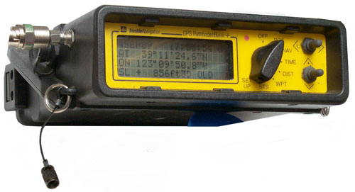
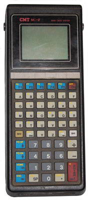
email from KL:
In your teardown of the TDC1, you wrote:"Under the black rubber door on top there is a DB-9m connector and a Jack for modular plug, maybe LAN or modem?"The TDC1 is a Symbol PDT-3300 handheld computer moulded in Trimble yellow. The Sokkisha SDR33 data collector is built on the same platform as well.The DE9 port on top of the unit is meant for connection to a barcode scanner, and is wired for low level black/white light level signalling.The modular jack up top is the COM2 serial port, the 25 pin port on the bottom is the COM1 port.Also, the TDC1 can run two different pieces of software from Trimble, the less-capable Asset Surveyor software, and the more sophisticated Survey Controller software.The survey controller software can be found here:the asset controller software is hiding on Trimble's site, here:Now you know!
KL
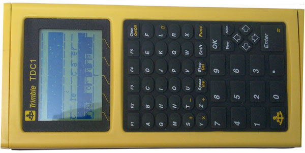
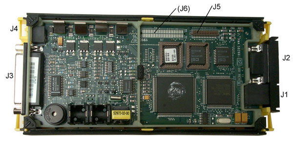 |
 |
| Seperating the sandwitch of
two boards yeilds the final assemblies. |
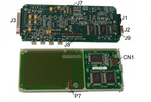 |
| Shown below are all the
parts at this stage. |
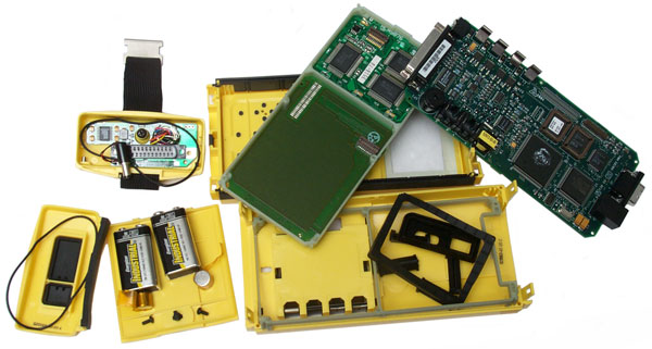 |
| After assemblying the
working parts the LCD is still messed up, so next is to
clean the zebra strips. Trimble TDC1 LCD w/ two zebra strips still attached, open frame & EL back light on PCB |
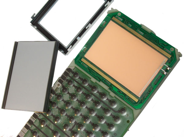 |
| Bummer - cleaning the zebra
stripes makes no difference. Something else has gone
wrong. |
| p/n |
One End |
Other End |
|||
| 14284 |
RS-232
Data Download |
DE9P |
DE9S |
||
| 16041-00 |
Data
& Power Adapter |
Pwr
I/O-1 |
Lemo |
5-pin |
|
| 20898 | Lemo-to-Hirose
Cable |
Hirose | 12 pin |
Lemo DE9S |
6 pin |
| 16454 |
1 PPS
out , event In |
Lemo | 7-pin | 2 ea.
BNC |
|
| 17202 |
Null
Modem Cable |
DE9P |
DE9S |
||
| 17664 |
Pro XL to MC-V | DB9F |
DB37F | ||
| 17671 |
Pro XL
to RS232 ? |
DB25F | DB37F | ||
| 18542 |
Camecorder
Battery |
2 term |
Lemo |
6 pin | |
| 28407 |
TDC1 to 4600LS Y-Cable | ||||
| 18826 |
Lemo-to-DB9
Connector |
||||
| 18827 |
Serial
Data Cable |
Lemo |
7-pin |
DE9S |
|
| 22165 |
4000/External
Sensors Cable |
||||
 |
Trimble 20887 Data Logger
to PC Cable 12 pin Hirose to DB-9F |
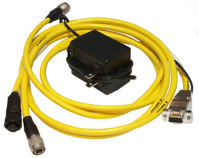 |
21449 Pathfinder Basic- PC
- Wall Wart - Data Logger Cable Pathfinder connector 7 sockets Data Logger 12 pin Hirose PS BD-9F |
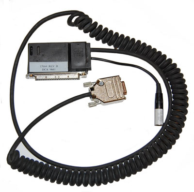 |
Pro XL to MC-V P/N 17664 Rev BDB9F to DB37F1 N/C 2 >>23 Orange 3>>24 Red 4>>34 Black 5>>22 Shield 6>>N/C 7>>21 Brown 8>>N/C 9>>33 Blue Pin 1 B- Pin 20 B+ Pin 25 is Green not connected to 9 pin Pin 26 is White not connected to 9 pin Power Conn Pin 1 B+ Pin 2 N/C Pin 3 B- |
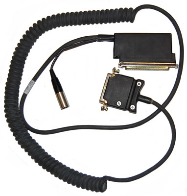 |
P/N 17671 REV CDB25F to DB37F I belive this is Pro XL to Compuker RS232 .2>>24 Red 3>>23 Orange 4>>26 White 5>>25 Green 15>>34 Black 20>>21 Brown 21>>33 Blue N/C>>1 B- N/C>>20 B+ |
 |
 I think the battery contacts to the right are negative. Some type of checking needed to be sure. |
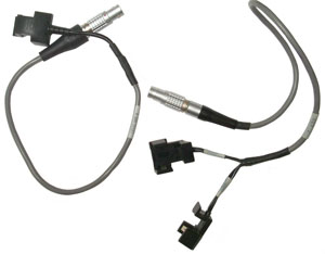 The single battery cable is the 18542 rev B, dca
9523.
The single battery cable is the 18542 rev B, dca
9523.These were for use by surveyors and/or base/reference stations. Came out in the 1985 time frame, predating the Trimpack, but based on the same 4754465 Trimble patent as the Trimpacks.
They are much larger than the Trimpaks.
4000 series box: 6" high x 12" wide x 14" deep excluding battery pack.
Antenna Output 10 Volts
There are a large number of 4000 series GPS receivers and so far I haven't found out much about them.
LSU - 30 Years of GPS, 30 Years of Trimble -4000ST mounted on Yak on Mount Everest about 1990
"A Geodetic Survey Receiver with up to 12 L1 C/A-Code Channels, and 12 L2 Pseudo-P-Code Channels", presented by M. T. Allison, D. Farmer, G. Lennen, and K. Martin at the Third International Technical Meeting of the Satellite Division of The Institute of Navigation, Colorado Springs, Colo., September 1990.
p/n
Description
15001-01
Surveyor 4000 (ST/SST?)
Accuracy may be 1 cm + 1 mm per km seperation between base and rover.
" To remove 4 large and 4 small screws to remove back cover.
The outer case can now be lifted up and off the main chassis.
There are 4 batteries on the bottom PCB at the lower left.
Also more batteries on the top PCB below the RF box.
The PCBs are held in the chassis by a round plastic rod.
Remove the Screw holding the rod to free up the boards.
Antenna Connector:
Lemo FFA.1E.250.CTAC50
Alpine Electronics, San Jose
"
Just behind the rear connector block on the PCB there's a rectangular outline with no components installed. This is the patented PN corrolator. The corrolator for this receiver is on the top PCB, see photo just below.
"
The connectors shown at the top are at the back of the chassis
and must be disconnected in order to slide out the board. Left to right: Power Supply, Analog In, Serial 1, Serial 2, System/Display.
The 3.5 V RTC battery is totally dead.
The large (3 3/4" x 7/8") 64-pin IC in the upper right corner is a 68HC000 same as the Trimapack.
The rear panel shows the key Trimble patent.
This receiver does not use a custom IC, but rather used discrete
ICs to implement the GPS PN correlator so this is probably
a first generation Trimble receiver.
In the lower left where the coax cable is feeding the IF
you can see a box outline where there are slots in the PCB. This is the correlator circuit, later to become an IC.
The bottom central connector is labeled "Timing Bus" and the
lower right connector is labeled "Digital Bus". These are the same functions as in the Trimpack.
"
There are two DS1221 ICs that prevent corruption of the 58257 (32Kx8bit) static RAMs (9026 date code). Although only one battery is required Trimble connected both of them. The battery on pin 2 has gone dead but the one on pin 15 is still good. So the RAM contents are probably still good. So I'll just replace the two dead batteries.
32 RAMs each 32 K bytes = 1 M byte of RAM on 10" x 10" PCB.
Near the connector there are 4 Bank Select jumpers. 0/1 and 0/2 are installed.
"
At power up there were a bunch of warnings about corrupted RAM and taking the defaults caused it to be erased. Fitted with both L1 and L2. About 10 am got to this screen where it's trying to find a satellite. The Icon to the right of "AC POWER" is the Antenna symbol. When the antenna is disconnected it beeps and the Icon turns off.
Based on the Trimpacks this may take many hours.
Turning off L2 to try and help it get a fix causes the Memory Left to change from 29 to 38 hours.
GEODESIST
16 Channels
NAV Ver 4.80 19-NOV-92 TEST
SIG VER 4.20 9-APR-90
BOOT VER 2.00 21-NOV-89
Dual Freq (L1/L2) ON & Installed
Max Epochs @ 8 SVs, 15 Sec: 4365
No. of RS-232 Ports: 2
Dual Power Inputs: Installed
Ext Timebase Off & Installed
Event Marker -On & Installed
1 PPS Out Off & Installed
Fast Measurement Rate Installed
RS-232 FW Upgrade Installed
RTCM-104 Inputs Installed
RTCM-104 Base Station Installed
Navigation Package Installed
Kinematic Mode Installed
COCOM ALT/SPEED Limits Installed
"
Pressing:
STATUS button
OPTIONS soft key
leads to the Receiver Configuration pages shown at left.
16856-01
GEODIST Note 1
STATUS \ OPTIONS:
Model: GEODIST
# of Chan: 16
Nav ver: 4.80 31-jul-92
Sig ver: 1.15 11-Mar-91
Boot ver 2.00 21-Nov-89
Dual Freq (L1/L2+P) ON & Installed
Max Epochs @ 8 SVs,15 Sec: 17502
# RS-232 Ports: 2
Dual Pwr Inputs Installed
External Time Base Off & Instaslled
Event Marker -Off & Installed
1 PPS Out On & Installed
Fast Meas Rate InstalledNav Pkg Installed
Kinematic Mode Installed
COCOM Limits Installed
"
"
The time and date are correct! This one has not yet been checked for dead batteries, but the RTC battery must be OK.
STATUS \ OPTIONS:
Model: GEODETIC SURVEYOR II
# of Chan: 16
NAV ver: 4.82 23-Apr-93
Sig ver: 1.15 11-Mar-91
Boot ver: 2.00 21-Nov-89
Dual Freq (L1/L2+P) On & Installed
Max epochs @ 8 SVs, 15 Sec: 17502
# of RS-232 ports: 2
Dual Power Inputs Installed
External Timebase: Off & Installed
Event Marker -ON & Installed
1 PPS Output Off & Installed
Fast Meas Rate Installed
RS-232 FW Update Installed
RTCM-104 Inputs Installed
RTCM-104 Base Station Installed
Navagation Pkg Installed
Kinematic Mode Installed
COCOM Alt/Speed Limits Installed
16856-01 GEODETIC SURVEYOR II Note 1
Powers up with time and date that are close.
But after about 8 minutes:
RESTARTED BY HARDWARE WACHDOG
FRI 08-MAY-09 15:30
then after about a minute goes to the power up screen.
The screen is flashing on and off and the beeper is beeping.
Pressing and holding the power button does NOT turn if off.
GEODITIC DUAL-FREQUENCY SURVEYOR II
Testing Channels
That may be saying that "Testing Channels" is failing.
But after upluging the power cord and restarting it has found a SV, but then the watchdog restarts it.
Two things are apparent when visually inspecting this receiver.
1) the correlator is populated whereas on the 15001-01 at the top of this table it was just an outline on the board.
2) a connector is loose and may have it's center conductor broken off inside the shield box.
There's an axial lead resistor between the loose connector and the board and it has enough compliance so that the wire did not break.
Cycled or Wiggled all the connectors to wipe contacts and so far it appears to be working.
17:30 UTC try again,
Although when powered up there are error messages:
Error -214: P-CODE I & Q
Error -12: L1
Phase Lock Loop Rang Error (1.0 - 3.0)
PLL1 = 0.00 PLL2=0.00
**Press Any Key**
These were caused by not re-plugging J8 onto it's header.
17:37 tracking a SV,
17:38 Calibrating - Waiting for Lock
17:42 Calibrating 5 cycles to go
17:42 Wait: 3 Healthy SVs, SV22
El/Az: 22, 31, 32, 3, 6, 9 are al above horizon
Moved 17572-00 antenna from kitchen window to outside on tripod
18:03 Logging for 0:01 151 hours left, SV22, 14, 19
18:42 SV 22, 14, 11, 32 (Note some older receivers have a problem with SV 32, but this one is OK)
24840-61 SSi
26541-00
L1 only with MSK LF Beacon output
26541-02 L1 only with MSK LF Beacon output & CW output
26541-10 L1 & L2 with MSK LF Beacon output
26541-02 L1 & L2 with MSK LF Beacon output & CW output
24840-01
4000SSI Geodetic Surveyor
24840-51 4000SSi Geodetic System Surveyor
24840-21 4000SSi Site Surveyor
28454-71
MSGR 27612-71[SM] Note 1
Trimble Military GPS RTKGPS system.
Note the receiver that was with the system looked like the MSGR shown above, but was not allowed into the public domain (probably contained the crypto capability).
This was for sale on UK eBay by ace-surplus and with their kind permission I'm showing the system here.
Type............................. GPS Survey
Make............................ Trimble
Model.......................... 4000SSE Geodetic Surveyor
Voltage....................... 12-24-100-240v Charger
Serial Number........ 3238A01467
Condition.................... Used / Good
Special Notes.......... With software update CD rom MSGR System Update Version A
Description............... Fitted with the following options....
Channels 18
NAV Version 5.71
SIG Version 1.26
Boot Version 3.31
Dual Frequency L1/L2+P
Max Epochs @ 8SV, 15 sec : 14296
2 x RS232 ports
Carrier Phase Processing Installed
RT Survey Data Installed
Local Datum/Zones Installed
Kinematic Mode Installed
Dual power inputs
Fast Measurement Rate
Cocom ALT/SPEED Limits Installed
P-Code
And with the following accesories.....
1 x 4000SSE Receiver with Battery tray and 4 camcorder batteries.
1 x TDC2m Survey Controller
1 x Field Support Module
1 x Battery Pouch
1 x Military Trimtalk Radio (RTP R/T)
1 x Trimtalk 900 Base and Rover Antennas
1 x Tripod adapter plate
1 x Backpack c/w 2 antenna extention poles
1 x transit case large
1 x transit case small
1 x Range pole bracket for TDC2m
1 x range pole allen key
1 x magnet mount
1 x tribranch
1 x tribranch adaptor
1 x height rod with bag
1 x military L1/L2 with ground plane component
1 x antenna bag (piza bag)
1 x Rover/Base Trimtalk to antenna mount RG58
1 x Cable HMMWV Lugs to FSM(Pheonix 6M)
1 x Cable Cigarette Lighter to FSM(Pheonix 6M)
1 x Cable Alligator Clips to FSM(Pheonix 6M)
1 x Cable FSM AC Power Cord C13 UK Plug
1 x Cable FSM AC Power Cord C13 US Plug
1 x Cable SGR/Trimtalk/FSM (Lemo 5M) to 1 battery Clip (With PTC)
2 x Cable SGR/FSM (lemo 5M) to 2 each battery clips (with PTC)
1 x Cable Y-Power SGR/FSM (Lemo 5M) to (Lemo 5F)
1 x Cable L1/L2 (suhner N connector) to SGR (Lemo 1E coaxial) RG58 3 metre
1 x Cable L1/L2 (Suhner N connector) to SGR (lemo 1E Coaxial) RG58 10 metre
1 x Cable L1/L2 (Suhner N connector) to SGR (lemo 1E coaxial) RG214 30 metre
1 x Extension (Suhner N) to SGR (N) with line Amp RG213
1 x Extension (lemo 5M) to (lemo 5F) 16 feet
1 x Extension (lemo 5M) to (lemo 5F) 8 feet
1 x Cable SGR(lemo 7M) to Trimtalk (Lemo 5M) 3 metre
1 x Cable TDC2M (Fisher 5M) to SGR (lemo 5M) 3 metre
1 x Cable TDC2M (Fisher 5M) to FSM (lemo 5F)-Null Modem 0.25 Metre
1 x Cable RS-232 FSM(db9M0) to PC (db9F)
1 x Cable Hot start-SGR(lemo 10M) to SGR (lemo 10M) 2 metre
1 x Cable SINCGARS (phoenix 6M) to SGR(lemo 7M) 2 metre
1 x External refrence oscillator cable
1 x Kinematic quick release bracket
Note 1 - This receiver uses the GPS P-code signal which, by U.S. Policy, may be switched off without notice.
UNAVCO - Trimble Support Documents memory battery replacement & field use tips
Receiver & Antenna Table from UNAVCO
+----------------------+-------------------------------------------------------+
| TRIMBLE Receivers    |  Description                                          |
|  IGS Codes           |                                                       |
+----------------------+-------------------------------------------------------+
| TRIMBLE 4000S        |  Single frequency model                               |
| TRIMBLE 4000SE       |  Single frequency with internal antenna               |
| TRIMBLE 4000SL       |  Single frequency model                               |
| TRIMBLE 4000ST S     |  Single frequency model                               |
| TRIMBLE 4000ST       |  Dual frequency model                                 |
| TRIMBLE 4000SX       |  Single frequency model                               |
| TRIMBLE 4000SLD      |  Dual freq. L1 C/A; L2 squaring                       |
| TRIMBLE 4000SST      |  Dual freq. L1 C/A; L2 squaring; L2 P-code optional   |
| TRIMBLE GEODESIST P  |  Dual freq. P-code on L1 and L2 (same box as SST)     |
| TRIMBLE 4000SSE      |  Dual freq. P-code on L1 and L2; xcr Y-code           |
| TRIMBLE 4000SSI      |  Dual freq. P-code on L1 and L2; xcr Y-code           |
|                      |  ("Geodetic Surveyor 4000SSi")                        |
| TRIMBLE 4000SSI-SS   |  Dual freq. P-code on L1 and L2; xcr Y-code           |
|                      |  ("Site Surveyor 4000SSi")                            |
| TRIMBLE 4400         |  L1/L2 receiver, enhanced L2 tracking                 |
| TRIMBLE 4600         |  L1 receiver, with internal antenna                   |
| TRIMBLE 4700         |  "Total station 4700" (external antenna)              |
| TRIMBLE 4800         |  L1/enhanced L2 receiver,                             |
|                      |   with internal antenna and radio modem               |
| TRIMBLE 7400MSI      |  L1/L2 receiver, enhanced L2 tracking                 |
+----------------------+-------------------------------------------------------+
| TRIMBLE Antennae     |  Description                                          |
|  IGS Codes           |                                                       |
+----------------------+-------------------------------------------------------+
| TRM10877.10_H        |  4000SX Helical, Model 10877.10                       |
| TRM10877.10+SGP      |  4000SX Micro, square groundplane, Model 10877.10     |
| TRM10877.10+RGP      |  4000SL Micro, round groundplane, Model 10877.10      |
|                      |   (with pyramid patch antenna cover)                  |
| TRM12562.00+SGP      |  4000SLD L1/L2, square groundplane, Model 12562.00    |
| TRM12562.10+RGP      |  4000SLD L1/L2, round groundplane, Model 12562.10     |
| TRM4000ST_INT        |  4000ST L1 Internal                                   |
| TRM14156.00-GP       |  4000ST Kinematic External, Model 14156.00            |
|                      |   (no groundplane)                                    |
| TRM14177.00          |  4000ST L1 Geodetic, Model 14177.00                   |
| TRM14532.00          |  4000ST L1/L2 Geodetic, Model 14532.00                |
| TRM14532.10          |  4000SSE Kin L1/L2, Model 14532.10                    |
| TRM16741.00          |  Compact Dome, Model 16741.00                         |
| TRM17200.00          |  4000SE L1 Internal, Model 17200.00                   |
| TRM22020.00+GP       |  Geod. L1/L2 compact, with groundplane, Model 22020-00|
| TRM22020.00-GP       |  Geod. L1/L2 compact; w/o groundplane, Model 22020-00 |
| TRM23903.00          |  Permanent L1/L2, Model 23903.00                      |
| TRM23965.00          |  Compact L1 with groundplane, Model 23965.00          |
| TRM27947.00+GP       |  Rugged L1/L2 with groundplane, Model 27947.00        |
| TRM27947.00-GP       |  Rugged L1/L2 w/o groundplane, Model 27947.00         |
| TRM29659.00          |  Trimble L1/L2 Dorne Margolin element with chokerings |
|                      |   Model 29659.00                                      |
| TRM33429.00+GP       |  L1/L2 microcentered, Compact Geodetic, Model 33429.00|
|                      |   (with groundplane)                                  |
| TRM33429.00-GP       |  L1/L2 microcentered, Compact Geodetic                |
|                      |   (no groundplane)                                    |
+----------------------+-------------------------------------------------------+
| Old but still valid  |  New Codes                                            |
+----------------------+-------------------------------------------------------+
| 4000SX MICRO         |  TRM10877.10+SGP                                      |
| 4000SL MICRO         |  TRM10877.10+RGP                                      |
| 4000SLD L1/L2        |  TRM12562.00+SGP                                      |
| 4000ST INTERNAL      |  TRM4000ST_INT                                        |
| 4000ST KINEMATIC     |  TRM14156.00-GP                                       |
| 4000ST L1 GEODETIC   |  TRM14177.00                                          |
| 4000ST L1/L2 GEOD    |  TRM14532.00                                          |
| 4000SE INTERNAL      |  TRM17200.00                                          |
| TR GEOD L1/L2 GP     |  TRM22020.00+GP                                       |
| TR GEOD L1/L2 W/O GP |  TRM22020.00-GP                                       |
| DORNE MARGOLIN TRIM  |  TRM29659.00                                          |
+----------------------+-------------------------------------------------------+
JRC NPB-2J Beacon Receiver
Another LF beacon receiver.
4754465 Global positioning system course acquisition code receiver
This patent number is on all the Trimble GPS receivers I've seen. A very innovative patent. It greatly reduces the complexity of a GPS receiver compared to the prior art resulting in a smaller lighter receiver. But the newer Trimble receivers have gone back to double conversion front ends to help reduce interfering signals. Trimble also does not seem able to offer a 12 channel receiver using this technique.
4000 Series specific:
4754465 <see above>
4847862 Global positioning system course acquisition code receiver, Paul E. Braisted, Ralph F. Eschenbach (Trimble), Jul 11, 1989, 375/376 ; 370/317; 375/E1.003
Two channel, common LO, heading information5148179 Differential position determination using satellites, Michael T. Allison (Trimble), Sep 15, 1992, 342/357.03 ; 701/215
resolving the integer ambuiguity. double-difference wide-lane ("DD") integers, L1-L2 phase makes a wide lane5202694 P-code generation, Dominic Farmer, Kreg Martin (Trimble), Apr 13, 1993, 342/357.12 ; 380/46; 708/250
lower part count less complex way to generate the P-code5296861 Method and apparatus for maximum likelihood estimation direct integer search in differential carrier phase attitude determination systems,
5357527 Validation of RAM-resident software programs,
5359332 Determination of phase ambiguities in satellite ranges,
Trimble has turned over support of the Civilian versions of these to Navigation Electronics, Inc. -
https://github.com/NF6X/trimpack
2.10           N: GPS NAV DATA                         RINEX VERSION / TYPE
                                        2009-05-10 15:59:57 PGM / RUN BY / DATE
     .1024E-07   .1490E-07  -.5960E-07  -.1192E-06          ION ALPHA
     .8806E+05   .3277E+05  -.1966E+06  -.1966E+06          ION BETA
     .279396772385E-08  .177635683940E-14   319488     1528 DELTA-UTC: A0,A1,T,W
    15                                                      LEAP SECONDS
                                                            END OF HEADER
GPS TRIMPACK -Back to Brooke's Products for Sale, Navigation, GPS, Military Information, Home page
GPS History - Trimpack and Gulf War
FAS - Desert Storm Navigation -
H_wright - eBay - Power cord for automotive use, similar to the 12792-10 above.
American MilSpec - Trimpacks for sale
Mike Murphy - Trimpacks for sale
eBay seller j5w23 often has the 8 AA battery box and holder for sale
eBay seller zuludelta often has the 17572-00 "Military GPS Antenna"
Possible 40 dB preamp L1 GPS Antenna Suppliers:
AeroAntenna - The AT575-75AW-TNCF-000-RG-36-NM may work with the Trimpacks. It a 36 dB gain survey antenna (1"-14 female thread on bottom No Magnet) and works from 5 to 18 Volts (RG), uses a TNC(f) connectorDMF-50202N LCD Module Specs - includes how to adjust the contrast which fixed Manny's Trimpack low contrast problem.
Sensor Systems - S67-1575-58 Passive GPS Antenna makes a great re-radiator after a high gain amp.
This is the [an error occurred while processing this directive] page created 24 July 2003.

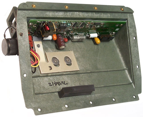
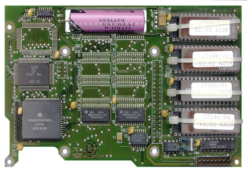

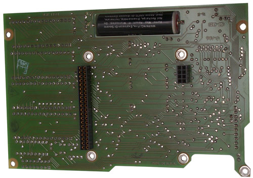

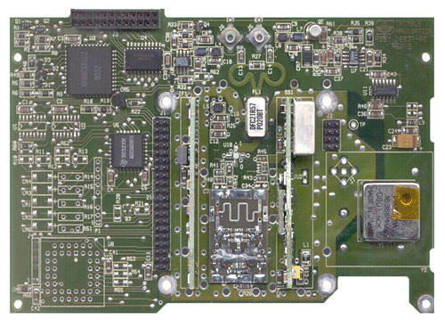
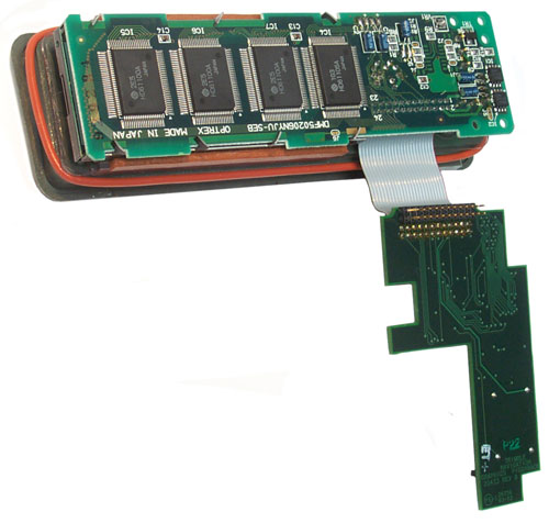

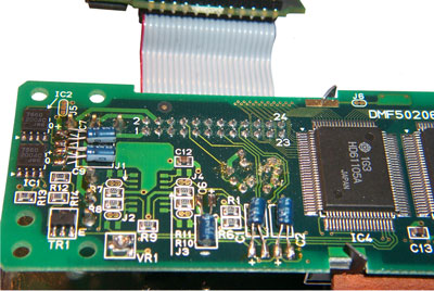


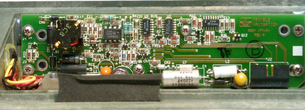
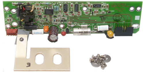
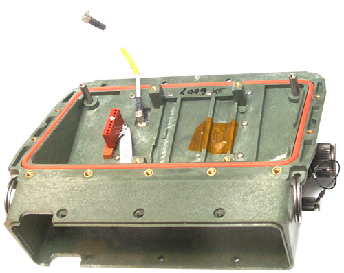
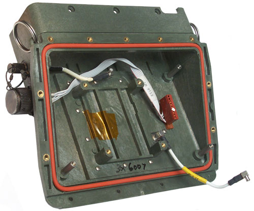

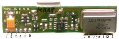
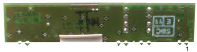
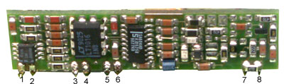
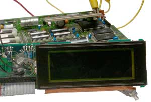
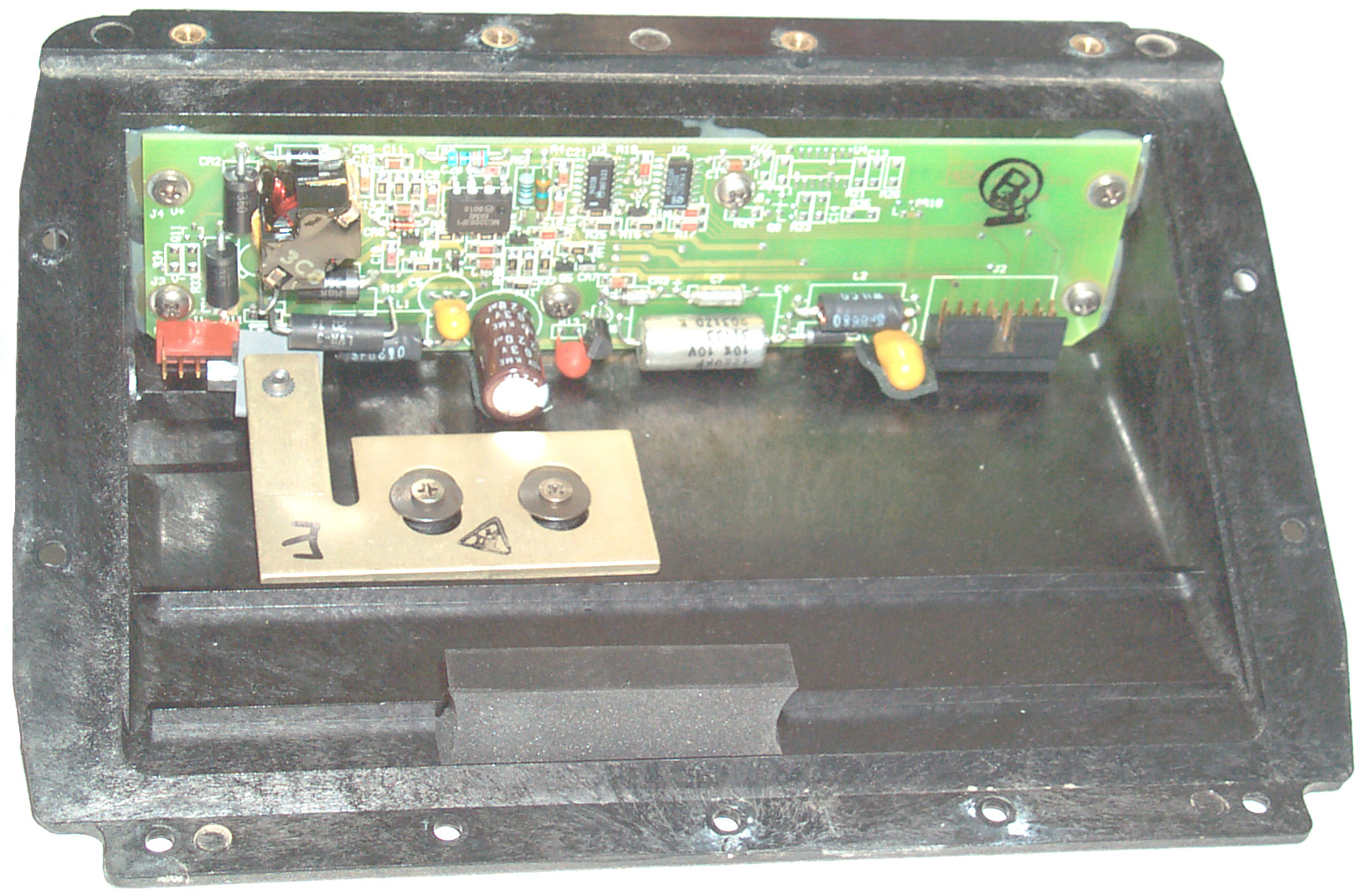
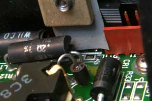

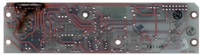
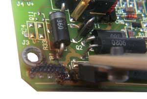

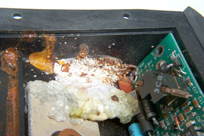
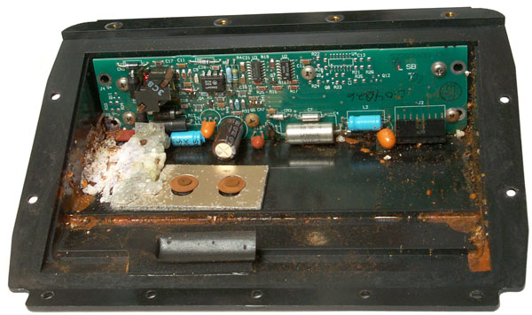
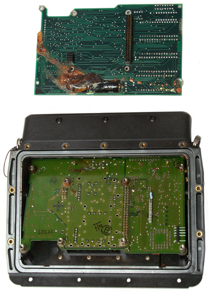
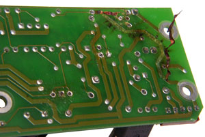
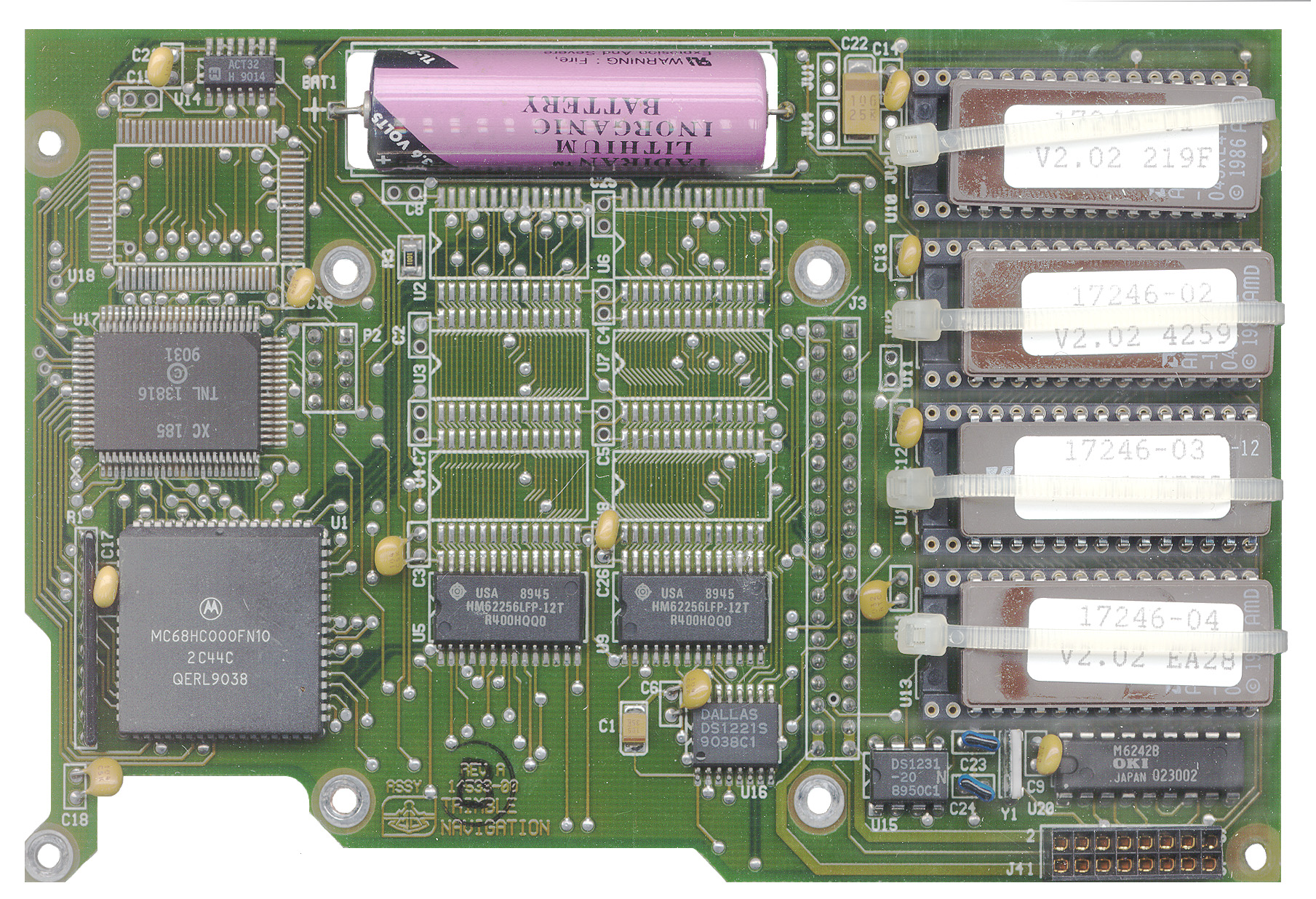
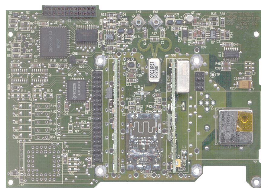


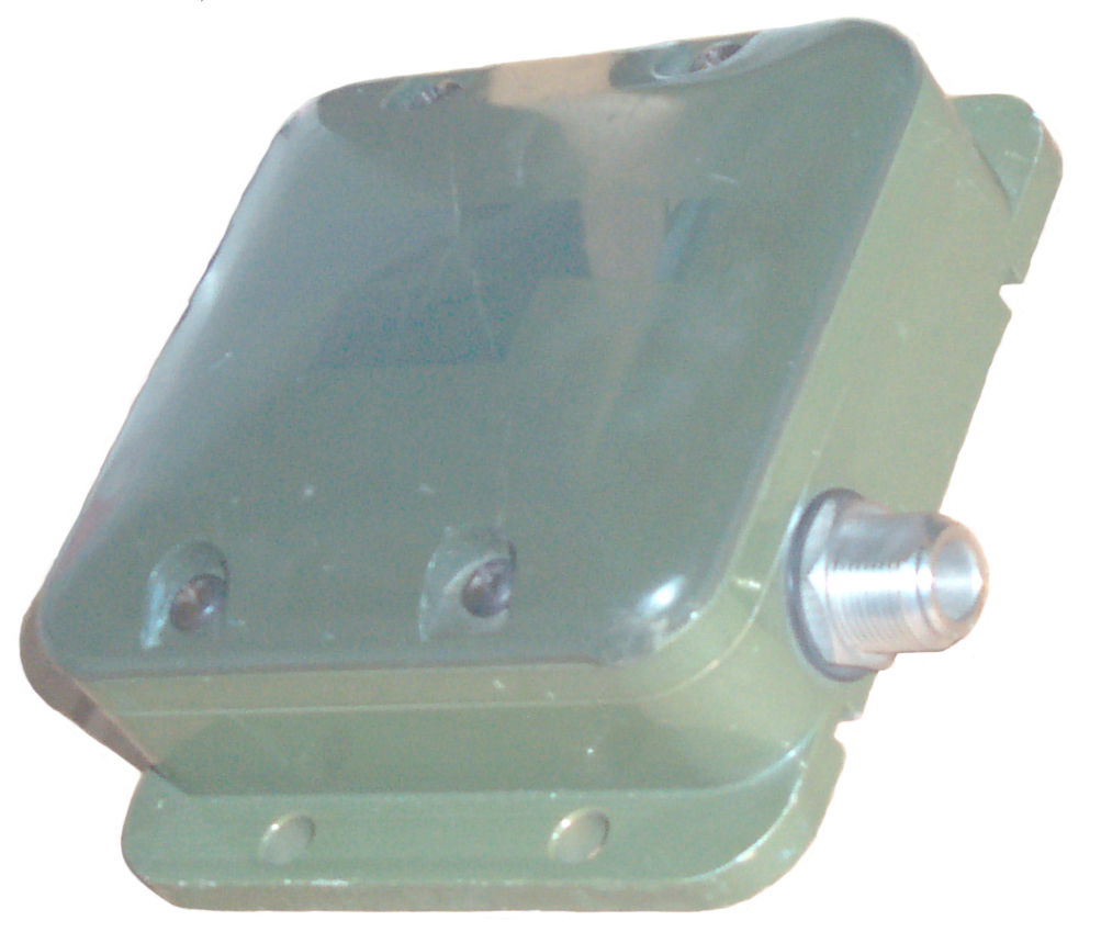

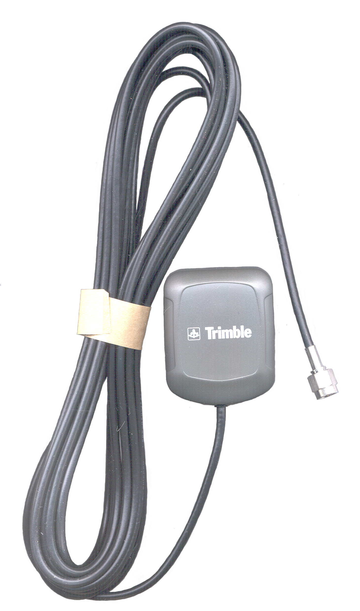
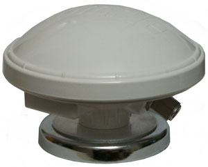
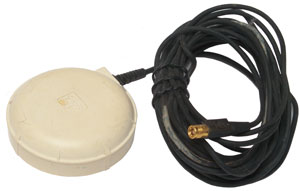
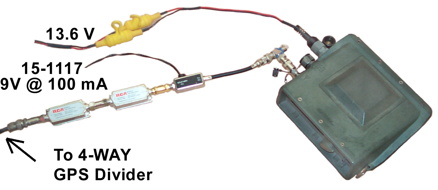
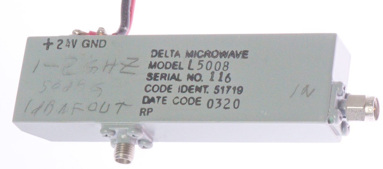
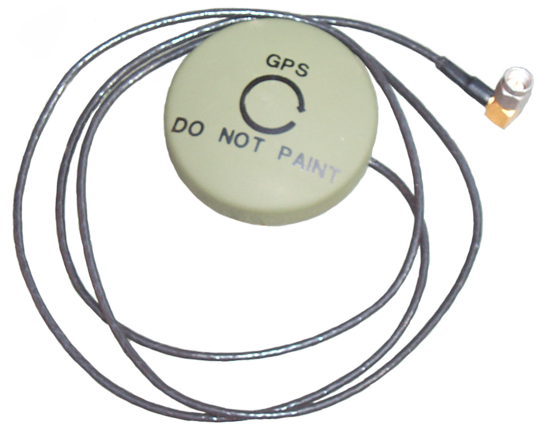


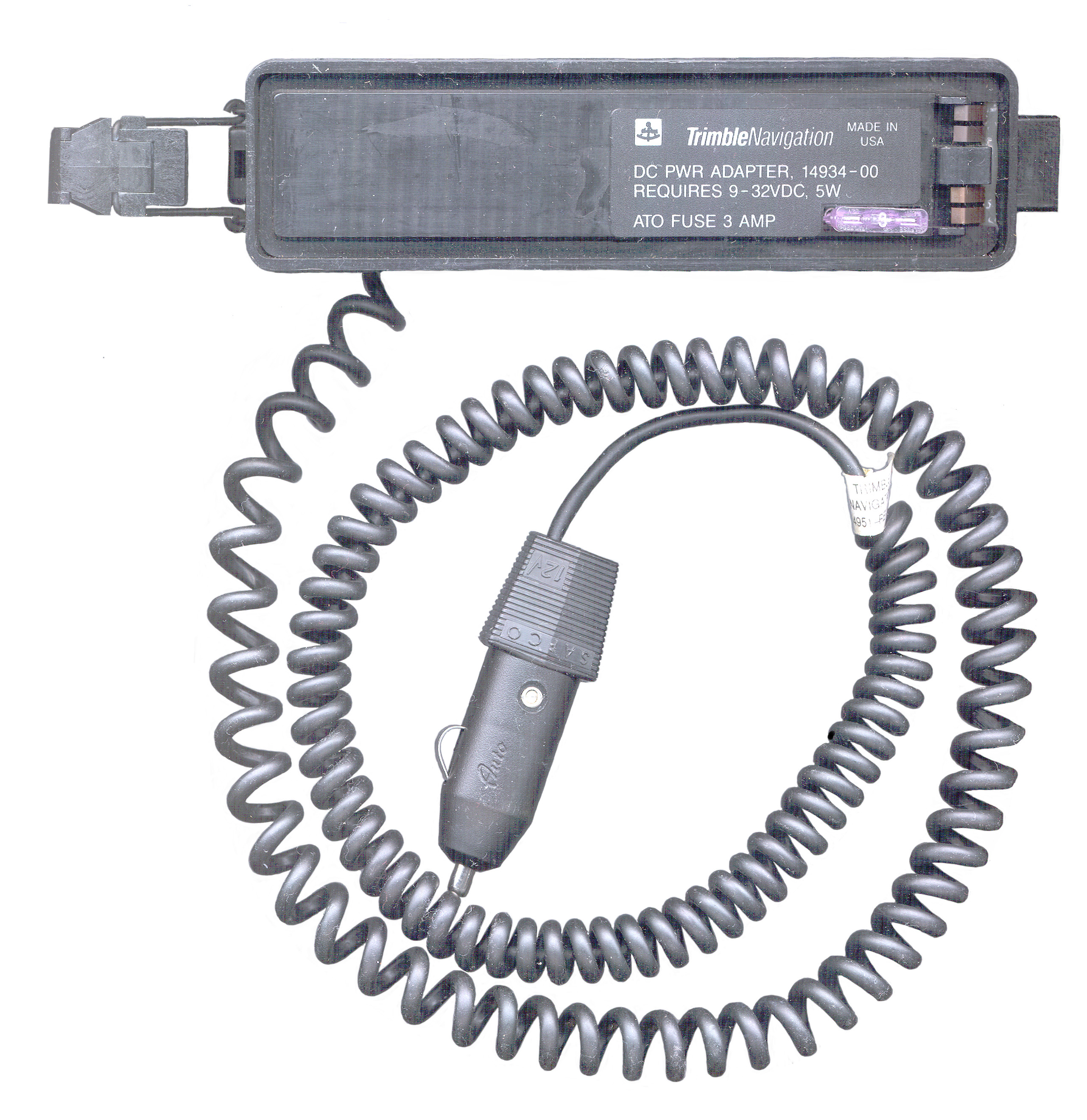
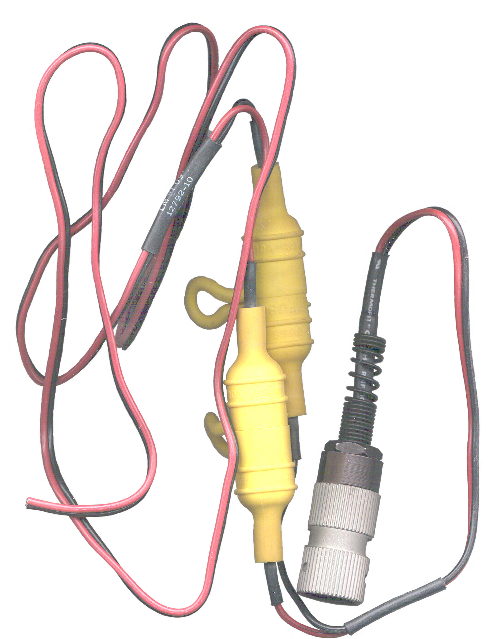
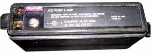


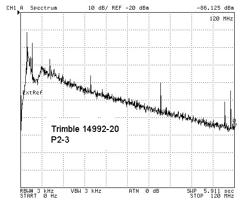
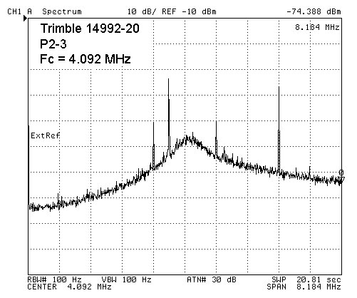
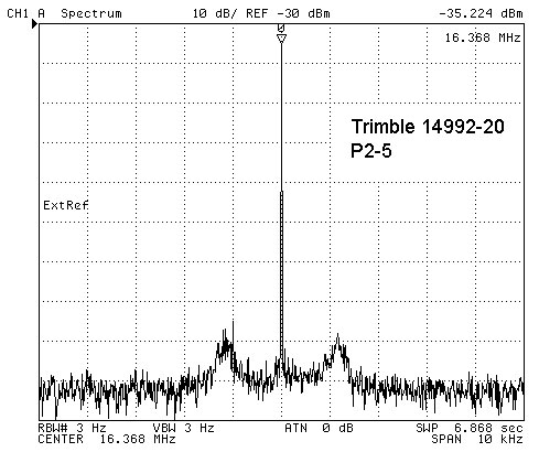
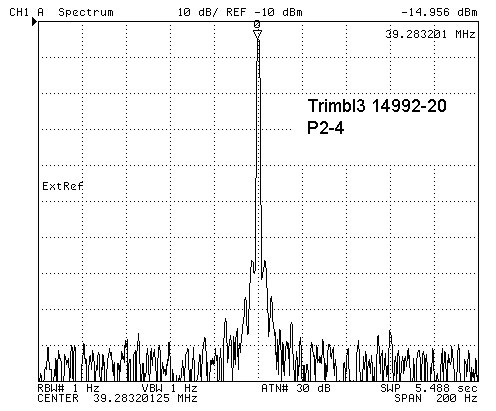
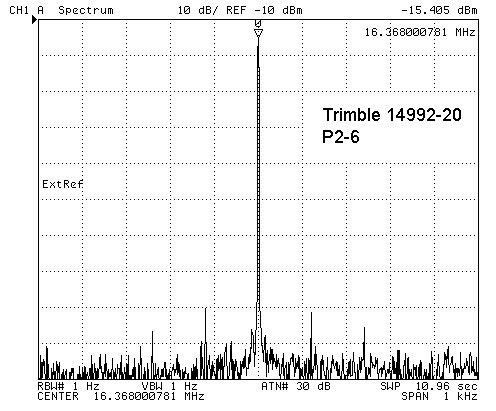

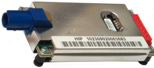
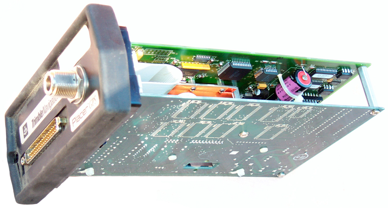

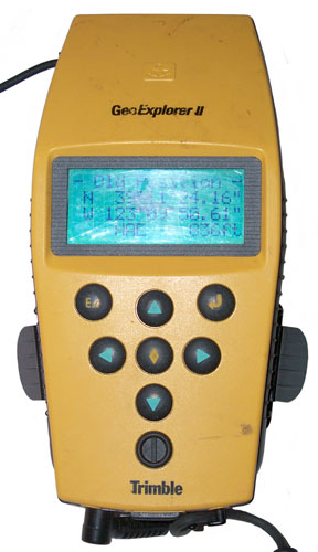

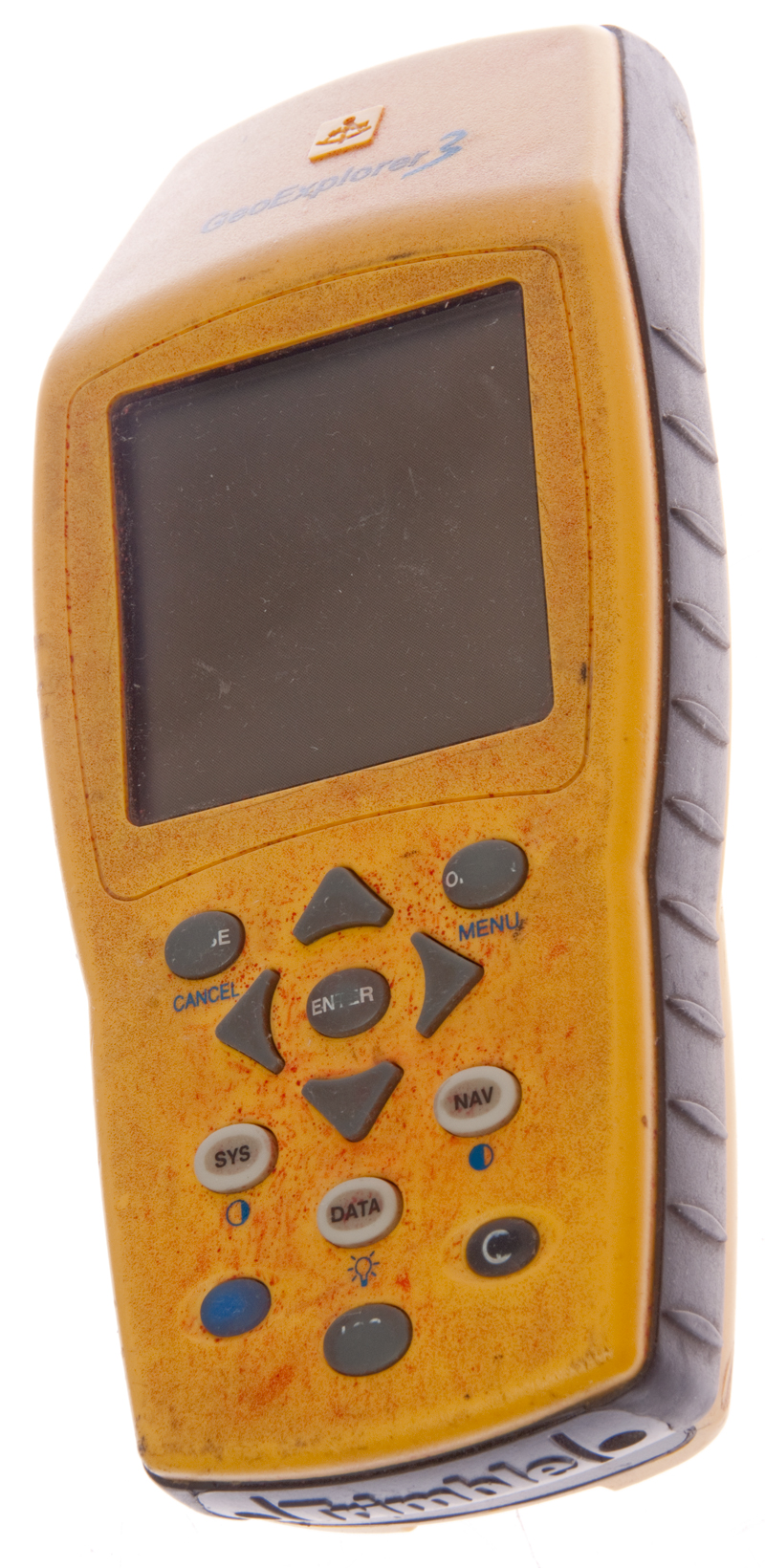

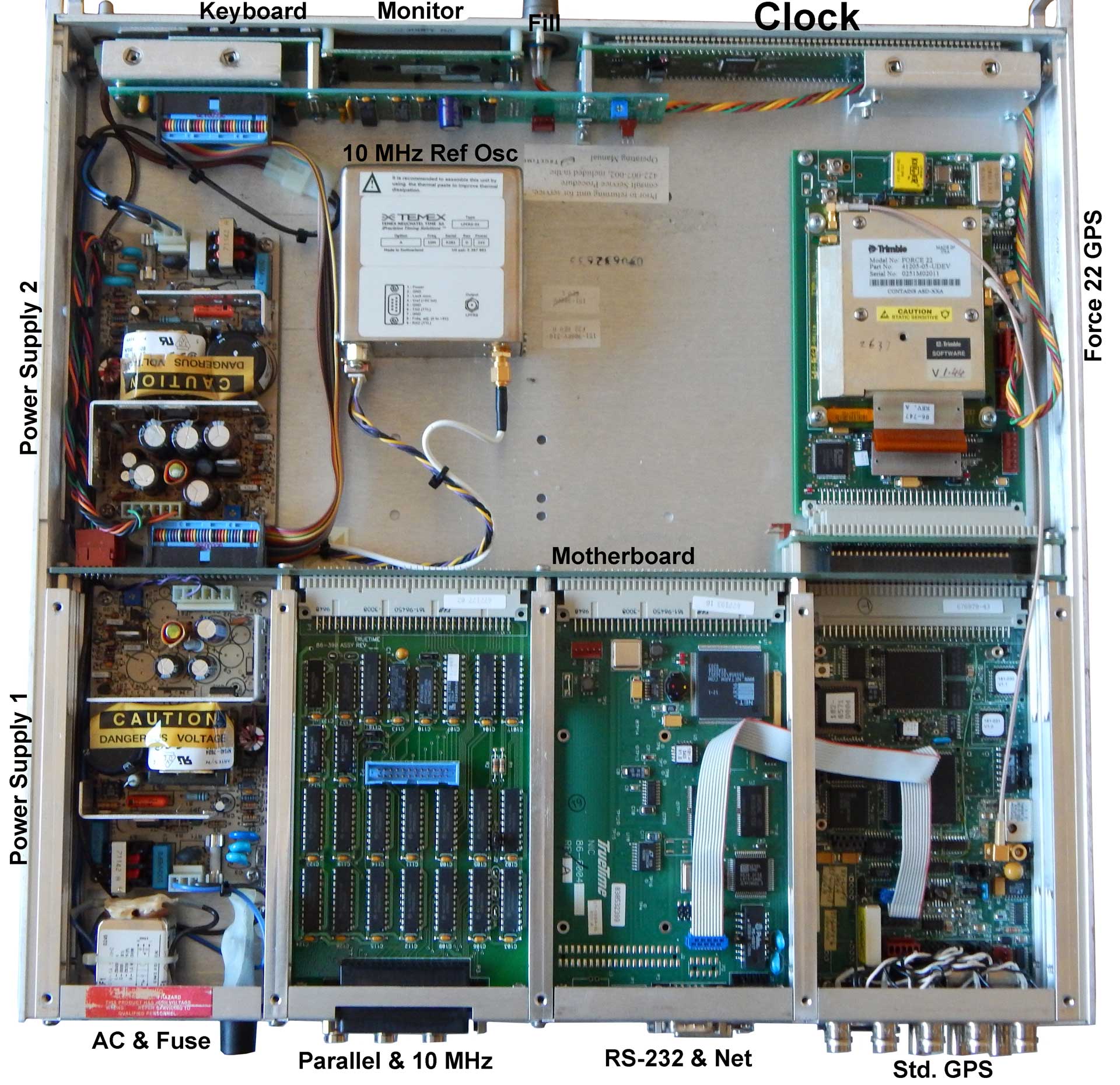


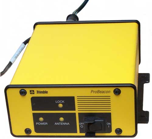
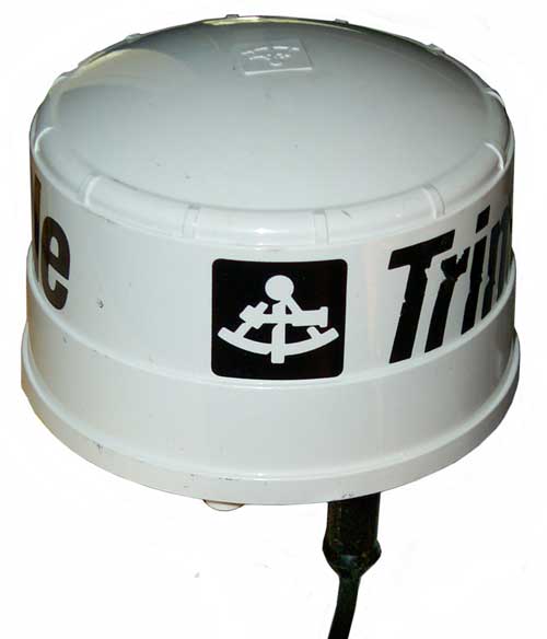
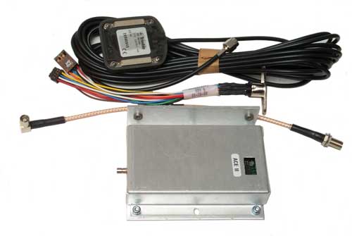
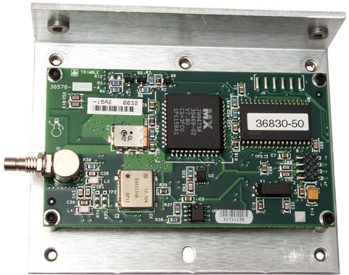
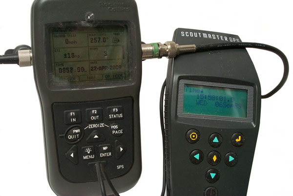
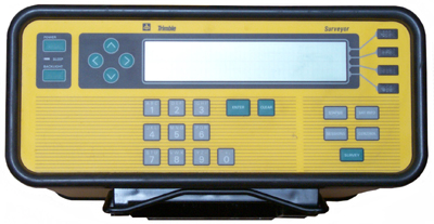
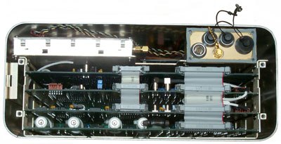
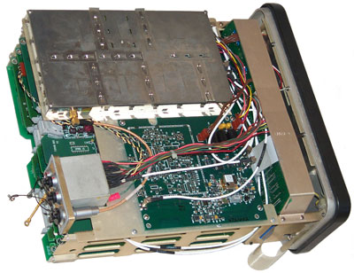
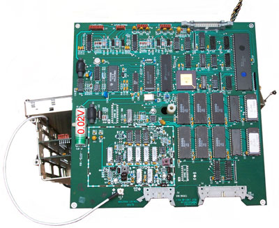
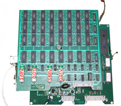
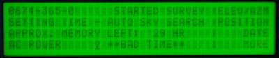
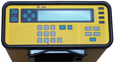
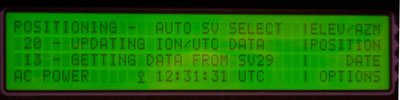

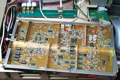
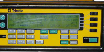
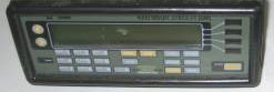
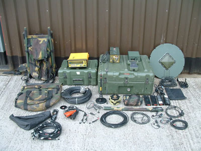
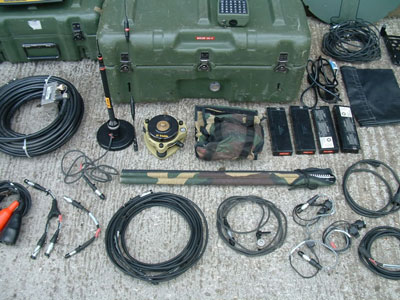
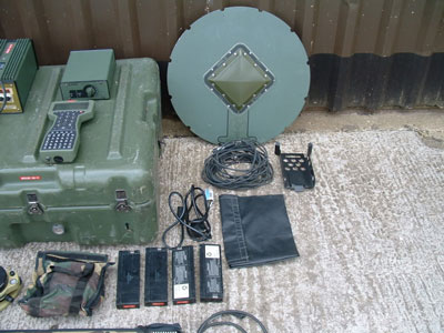
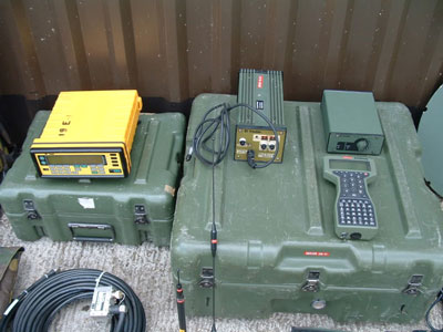
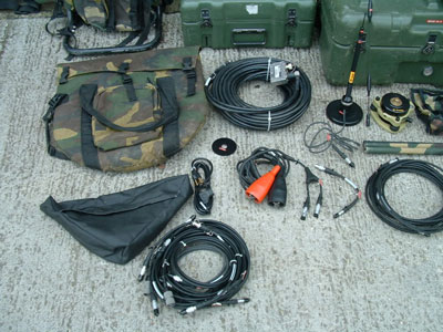
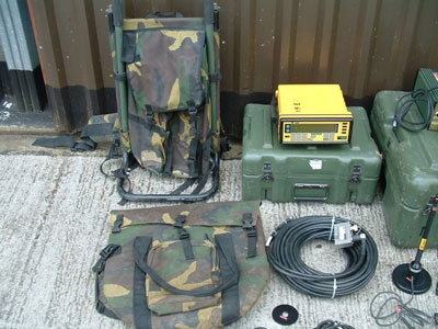
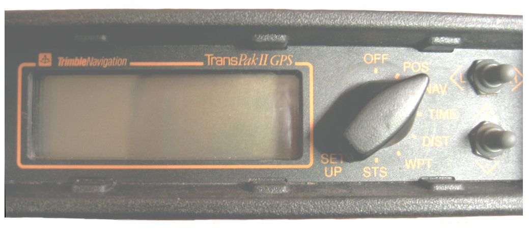