 |
 |
 |
| Front shown after plugged in and before reset no batteries installed |
Top - Front |
Rear |
Background
Since maybe the 1950s lab grade time
and frequency equipment has used 24 volts DC as a power
supply.
The HP 5087A 24 Volt Backup power supply was used to power the 5060A
flying clock Cesium standards. The HP 100 series of instruments
all use 24 VDC power sources.
This particular unit came from eBay with a foam filled bag in the battery space, like it has never been used.
This particular unit came from eBay with a foam filled bag in the battery space, like it has never been used.
Description
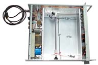
Battery Compartment Size
left to right 13" maxfront to back 7.25"
height 5" max
Front Panel
Meter switch Output or Battery :0 - 40 Volt meter, -5, 0, +5 Amp meterFuse Failure lamps: AC, AC, OUT, Battery
Battery Charge lamp & Switch
Interrupt lamp & reset switch
AC Power Lamp
Rear Panel
Ground PostJ1 - AC power connector 3 pins (cable connector = 97-3106A-10SL-3S)
- Black (hot) = pin A
- White (neutral) = pin B
- Ground = pin C
F1, F2 - Fuses
J2 - Alarm output 6 pin MS _______________
J3 - External Battery 4 sockets (cable connector = 97-3106B14S-2P + M85049/41-6A clamp)
J4 - Clock Out 4 sockets (cable connector = 97-3106A-10SL-3S) (this is only a 24 volt output)
J5 - Oscillator Out 5 sockets 97-_____?? (this is only a 24 volt output)
J6, J7, J8, J9 - 24 Volt Outputs 4 Sockets (cable connector = 97-3106B14S-2P + M85049/41-6A clamp)
For those applications where a MS grade connector is not needed I'll be using Power Pole connectors in a 24 volt configuration.
Power Supply near Transformer
This PCB has a single multiturn pot and a fuse.Power Supply with + Violet wire to battery
The PCB has two multiturn pots and a fuse.Battery Compartment
The battery compartment has a clamping mechanism that will take up to about 13.5 x 7.25" of batteries. This would hold 4 each 12 Volt 18 AH Gel cells like the TY-12-18. The quick connect connectors are about 0.266" type, not the more common 0.187" type like on the batteries, so if two batteries are used they need to be more like 40 Ah types. The wire colors are +Violet and -Red (seems strange).I'm using a couple of the very common 7AH 12 Volt Sealed Lead Acid (SLA) batteries instead of the much larger batteries that the 1290 was designed to hold. My concern is not long term power outage so much as outages that last for a few seconds. These batteries are not near as big so I'm looking at using a 1 foot long 2x4 as a rear spacer so that the battery clamp can operate.
The quick fit terminals will need to be changed to the smaller 0.187" type and a battery to battery jumper wire made up.
Pots
Looking from front of unit Ra to R3 left to right:R1 regulated output bus on back panel when on AC 24.5
R2 battery charge v 26.46
R3 battery float v 25.43
Info thanks to Paul WB8TSL
Related Equipment
Austron Time
& Frequency Instruments (24 Volt standby power)
FTS 4060 Cesium Standard (24 volt standby power)
HP 5060A Cesium Standard (24 volt standby power)
FTS 4060 Cesium Standard (24 volt standby power)
HP 5060A Cesium Standard (24 volt standby power)
Links
William Perry
has the connectors for a reasonable price.