AM-7148/GRC-206 HF RF Amplifier NSN 5985-01-149-1437

© Brooke  Clarke 2008


AM-7148/GRC-206
        Front
Background
Photos
    Front
    Bottom
    Rear
Overview
Connectors
Audio Cable   
    Non User Friendly Military Names
Remote Control
DC Power
AM-7152
Manuals
Related
Links

Background

This is the 150 Watt RF Amp covering 2 to 29.9999 MHz used to make a URC-113 radio which is used in the GRC-206 Program Pacer Speak.  It arrived with other GRC-206 system components still sealed in the military packaging, so it's New Old Stock (NOS).
AM-7148/GRC-206 New Old Stock 
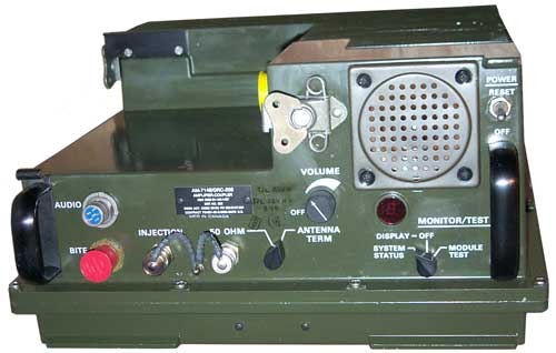
The Label says:

FSCM 37695  P/N 566084-806
CABLE, AUDIO
1 EA
FSCM 37965  P/N 5985-01-149-1437
(GFE)
H. F. POWER AMPLIFIER/ANTENNA COUPLER
1 EAF096038461437SM07
A     10/87
SERIAL NO 882

The packing bag is marked MAY 1986.

A stamp on the bag:
MAGNAVOX G&N
FT WAYNE, IN
P100 A2530  3 87
117E, T/I, C/E, S/1
If you know what this means let me know.
AM-7148 R.F. Amplifier in anti rust
                wrap
paper marked:
DATE OF MFG 1089 MIL-P-130F TYPEII

Inside duct tape was applied to the amplifier in many places and will take some cleaning to remove the sticky residue.

Photos

Front
AM-7148/GRC-206 Front
The BITE connector is a 6 socket mil connector.

The Injection connector needs more
research.  May be for 3.6 MHz signal for BITE, but it's still not clear.

The 50 Ohm connector is for test purposes.
The high power RF only comes out of antenna coupler High Voltage terminal on the rear panel.

The yellow cap is on the interface connector to the RT-1209A, RT-1209B or the RT-1444 connected on the back of the RT-1209.
Bottom
AM-7148/GRC-206 Bottom
I didn't expect the fan.
Rear
AM-7148/GRC-206 Back
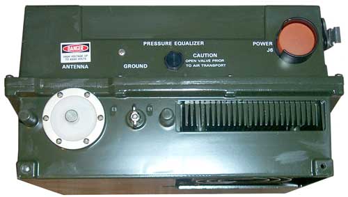
The power connector J6 is the common 4 pin military vehicle DC connector.

The antenna coupler is designed to load military whips like the AT-1011 or AS-2259.

The connection between the HV terminal and the base of the antenna should be a plain HV rated wire (not coax) and as short as possible.

Since there's only one DC power connector this must be the last equipment in the military vehicle chain of DC power.

Overview

J1 of the AM-7148 connects to the RT-1209() Power Amp/Antenna Connector.  The signals on this connector include the RF exciter output/receiver input, the frequency in MHz (6 bits), various control signals related to tuning the antenna, a frequency standard and DC power to the RT-1209(). 

AM-7148 & RT-1209
      Without the RT-1444
So this Amp/Ant Coupler could be used with a stock RT-1209 where you would control the radio via the RT-1209 front panel. 

Note the latch connector at the right of the photo is not hooked to the RT-1209, but the connector between the RT and Amp combined with the latch at the left rear anchor the RT.  When the RT-1444 is inserted between the RT-1209 front panel and the main chassis the front panel will move forward and the right latch will engage.  It's interesting that the designers allowed this use of the AM-7148.

The audio cable connects between the lower RT audio jack and the AM-7148, but is too short to do that on the setup shown at left.

Still TBD are the frequency standard details.  It's most likley a 5 MHz input that can come from the O-1814 RFO.


The AM-7148 audio connector J5 connects to one of the audio connectors on the RT-1209 and that's where the AM-7148 gets the receive audio to drive the speaker.  But there is no squelch in the AM-7148 only has an OFF-Volume control.


Connectors

#
Name
J1
RT interface
J2
BITE (A: BITE Fault, B: notTxRdy, C&D: Gnd)
J3
50 Ohm Ant
J4
Freq Std INJECTION
J5
AUDIO in
J6
DC Pwr (B=+27.5 V, A&C=Gnd) Rx 1Amp, Tx 19 Amp
E1
Ant Ground
E3
HV Antenna Terminal (missing on FO-9-1)

J4

The RT-1209 uses a 5 MHz reference oscillator for the frequency synthesizer and I'm guessing that the Freq Std INJECTION jack on the AM-7148 expects a 5 MHz reference sine wave at about 0 dBm.  BUT, the O-1814 RFO has a 5 MHz reference frequency output and so is compatible with the needs of the RT-1209.  Seems strange it's not used. 

Both the AM-1748/GRC-206 and the O-1814/GRC-206 were designed for the GRC-206 system so there must be a reason that they are not using a coax to connect the O-1814 5 MHz output to the AM-7148 5 MHz input.  If you know please tell me why.

Audio Cable

Packaged with the AM-7148 is an audio cable that's very short and formed into a "U" shape to take the Rx audio from the RT and feed it to the audio amp and speaker.
p/n 566084-806 10/87.

Non User Friendly Military Names

When I received this system there was an outer box containing a number of cables and in that box was another box labeled:
FSCM 37695  P/N 566084-806
CABLE, AUDIO
1 EA
(and a more information below
 like the NSN, contract number,
etc that I didn't read.

Emailed the seller and asked if the AM-7148 was being shipped in separate box.  Phone reply was it was in box with cables.  Sure enough, the box labeled as CABLE, AUDIO also shows on the label that it contains the AM-7148.  Maybe the order of the two items was alphabetical, but it would be much better to have done it in order of importance.

I've heard that very expensive military radio systems have been surplussed with a lot title like AUDIO CABLE or an equivalent and the buyer gets the lot for a song.

Remote Control

The RT-1444 is an add on to the RT-1209 (no letter) that allows remote control of the radio.  The connector on the side of the RT-1444 mates with J10 on the C11169/GRC-206  Signal Distribution Unit via a cable.  When the RT-1209 is the A, B or C version the system cable mates to the front panel connector on the RT and an audio "Y" cable is needed if the speaker in the AM-7148 will be used.

DC Power

The AM-7148 has a voltage limiting circuit that will regulate 28 to 30 VDC inputs to 27 VDC outputs, but if the input goes lower than 28 this circuit is non operational.  There is no switching mode power supply.  So to get max RF power out the input DC needs to be at least 28 VDC.  The test specs say 100 Watts out min and that may be at the minimum input of 18 VDC below which the low voltage cutout disconnects the input.

AM-7152

The AM-7152 should work in this system.  It's just a squelch box and so could be connected in series with the Audio from the RT to the AM-7148.

Manuals

TO 31R2-2GRC206-22 Maintenance Instruction with Illustrated Parts Breakdown, Depot, Amplifier-Coupler, AM-7148/GRC-206, NSN 5985-01-1491
Chapter 2 Installation refers to TO 31R2-2GRC206-2 and there is no Operation chapter.


TO 31R2-2GRC206-6WC-1 PM Inspection Work Cards

TO 31R2-2GRC206-2  Radio Communication System  AN/GRC-206(V)1 Immediate Maintenance w/IPB

TO 31R2-2GRC206-12 Radio Communication System  AN/GRC-206(V)1 and (V)2 Depot Maintenance w/IPB

See Radio Nerds for some GRC-206 manuals.

Related

The GRC-206 system is on the PRC-104 page.
The GRC-206 system components are also linked from the MT-6250 equipment rack (Mount) page.

Links

Back to Brooke's Products for SaleMilitary Information, PRC-68 Family of Squad Radios, U229 Audio Accessories, Audio Connectors, Electronics, Personal Home, PRC68.com page

[an error occurred while processing this directive] page created 24 Dec 2008.