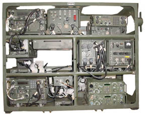
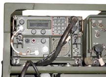
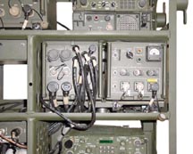
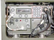
PRC-104 HF Receiver Transmitter
© Brooke Clarke, N6GCE 2003 - 2022Part Numbers
Versions
PRC-104
PRC-104A CONT
PRC-104B
Configurations
DC Power
Antennas
Audio Connector
104 Manuals
RT-1209 Receiver Exciter
Interface Connector
Mod for 160 meters
AM-6874 RF Amplifier Antenna Tuner
Related Equipment including separate ALICE web page
GRC-193 seperate web page
GRC-193 100 or 400 Watt system AM-6879
GRC-193A&B 100 or 400 Watt system
Documents
GRC-213 Vehicle Mounted PRC-104 with Squelch & VIC-1 Interface
AM-7152 Power Supply, Squelch & VIC-1
Mystery AM-7152
C-2299 Radio Relay Control Box
Antennas
Documents
GRC-206 Program Pacer Speak, H.F. band
Manuals
System Boxes
URC-113 150 Watt system
RT-1444 Remote Control appliqué
RT-1444A ALE and/or Hopping appliqué
C-11525/G Frequency Hopping Controller STAJ
RT-2000 Receiver-Transmitter
Voice Security
Data Security
Links
Background
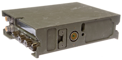
Hughes (Fullerton, California) won a competition to develop an HF radio to replace the PRC-47. The Collins PRC-515 was considerably larger and heavier.
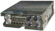
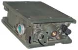
Frequency coverage is 2.0000 to 29.9999 MHz USB, LSB, CW (up to 300 WPM, i.e. GRA-71 compatible), FSK/DPSK up to 2400 bps. It's also known as the Improved High Frequency Radio, IHFR. Later PRC-104 models included compatibility with the Hughes C-11525/G anti-jam controller (STAJ) which is a frequency hopping system.
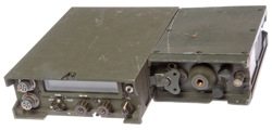
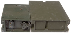
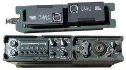
The PRC-104 is a modular radio that can be configured in a number of different ways:
PRC-104
Part Numbers
| p/n |
NSN |
Nomen |
Description |
| 755002A1214 755002A1255 |
CX-13030 |
Bench
Test DC Power Cable |
|
| 755002A1260 |
5820-01-065-4442 |
CX-13031 |
3'
Battery Extender Cable |
| CX-13032 | AgZn
Battery Charging Cable |
||
| 755002A7114-1 |
5995-00-405-9097 |
CG-3815/U |
2'
Coax Cable |
| 755002B9020 |
na |
na |
Instruction
Card |
| 755002A0057 |
na |
na |
Instruction Card |
| CY-7541/PRC-104 | Silver
Zinc Battery Case |
||
| 79A5029A000 |
6135-01-080-2886 |
CY-7875/PRC-104 |
Dual
BA-5590 Battery Case |
| 5820-01-065-4442 |
CY-7875/PRC-104A |
Dual BA-5590 Battery Case | |
| 6135-01-036-3495 |
BA-5590/U, 5590BA batt adapt 5590BAv2 batt adapt |
LiSO2
Primary
Battery |
|
| 6140-01-063-3918 |
BB-590/U |
Ni-Cad
Battery |
|
| 755002A3108 |
na |
CY-8291/PRC-104 |
Transit
Case |
| 75500A20850 | CY-7541/PRC-104 |
Battery
Case |
|
| 755002A7043-1 |
Silver-Zinc
Cell |
||
| 755002A3100 | CY-7542/PRC-104 |
Transit Case | |
| 2-2-344 |
8465-00-019-9102 |
ALICE | |
| 2-3-290 |
8465-00-001-6475 |
ALICE | Pack
Frame w/straps |
| na |
8465-00-001-6476 |
ALICE | Cargo
Support
Shelf |
| na |
8465-00-001-6477 | ALICE | Cargo
Tie Down Strap |
| 4139440-1 | H-189 |
Handset |
|
| na |
5965-00-043-3463 |
H-250 |
Handset |
| 755002A1000 |
5805-01-067-5388 |
KY-872/PRC-104 |
Leg
Key (Modified KY-116/U) |
| 2-3-291 |
8465-00-001-6476 |
ALICE | Cargo
Support
Shelf |
| 2-2-313 |
8465-00-001-6477 |
ALICE | Cargo
Tie-down
Strap |
| 755002A1650 |
MT-4874/URC |
Mounting
Tray |
|
| 75500A20550 |
5820-01-065-5044 |
AM-6874/PRC-104 A2 |
Amplifier Ant Coupler |
| 75500A20650 |
A2A1 |
Pwr
Amp |
|
| 75500A20750 | A2A2 |
Ant
Tuner |
|
| 755002A1800 |
AM-6897/U |
||
| 755002A1810 |
CX-13014 |
Cable |
|
| 755002A1811 | CX-13105 |
Cable |
|
| 6130-00-106-6445 |
PP-6241/U |
Battery
Charger |
|
| SM-D-182392 |
5985-00-646-2365 |
AT-271/PRC |
3
meter Fishing Pole Ant |
| SC-D-20938 |
5820-00-243-4127 |
AB-129/PRC |
|
| AT-1011 |
16' or 32' whip |
||
| 5985-00-106-6130 |
AS-2259 |
NVIS
antenna |
|
| 755002A0900 |
AB-1241 |
Base
for AS-2259/ |
|
| UG-349/U |
Adapter |
||
| AN/GRA-50 |
Dipole
Antenna
Kit |
||
| 755002A0050 | PRC-104 |
HF
Radio Set |
|
| 755002A0150 |
5820-01-069-2368 | RT-1209
A1 |
Receiver
Transmitter |
| A1A1 |
Mod-Demod |
||
| A1A2 |
Harmonic
Filter |
||
| A1A3 |
Synth |
||
| A1A4 |
Control
Panel |
||
| A1A5 |
Power
Supply |
||
| TM 11-5820-919-10+HR | |||
| TM
11-5820-919-12 |
Operator's
&
Maint Man |
||
| TM 11-5820-919-40-1 | |||
| TM 11-5820-919-40-2 | |||
| 5820-01-270-5099 |
RT-1209A | ||
| 755002C0050 |
5820-01-262-9550 | PRC-104B |
|
| RT-1209B | |||
| RT-1209B(V)1 |
|||
| 5820-01-269-5603 |
RT-1209B(V)4 | ||
| 755002C0150 | TM
11-5820-1046-12 |
||
| TM 11-5820-1046-20P |
Versions
PRC-104
Manuals in the TM 5820-919-xx range.
NSN 5820-01-141-7953
PRC-104A
Manuals in the TM 5820-919-xx range.
PRC-104B
Manual TM 11-5820-919-xx
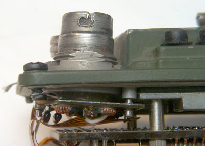
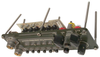
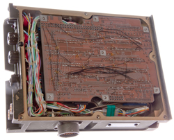
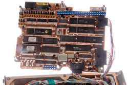
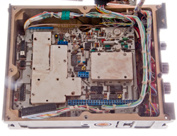
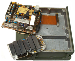
This unit is open because there's a short in the front panel. Also See What Goes Wrong
Top color dots on
PCB match connector color
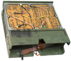 |
Top PCB folded open
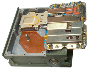 |
Bottom - has two
PCBs
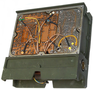 |
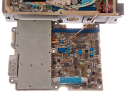
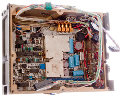
Bottom two PCBs
folded open
 |
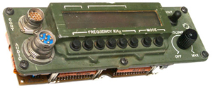
PRC-104A Front
Panel
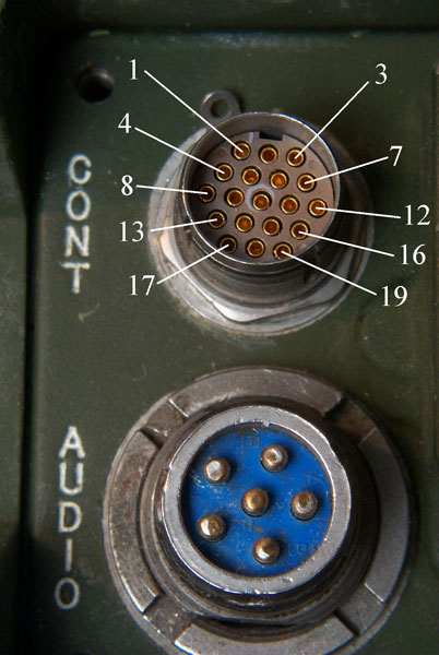
Control Connector
19 Sockets
 |
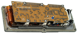
PRC-104A Front
Panel Back Side
Radio D-sub connector looks
same as on PRC-104
 |
PRC-104A (RT-1209A) Front Panel Versions 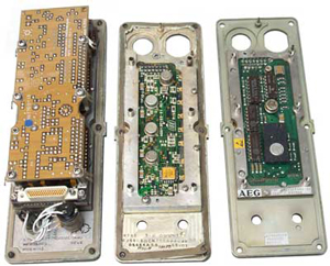 |
Variations in
PRC-104A Panels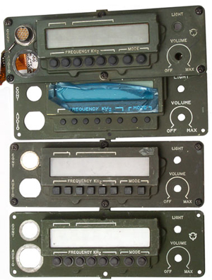 Round buttons w/boot Round buttons w/o boot Looks like new never used No boss under button panel Square buttons Round buttons w/boot |
After replacing both of the 6.8 uF caps and turning on the radio the LCD is blank but pressing LIGHT turns on the back light so the blown fuse problem was solved.
Configurations
HC-191 20 Watt Manpack w/AM
??? 20 Watt Vehicle w/ Audio Amp, Squelch, TTY Converter in one box
GRC-213 20 Watt Vehicle
PRC-105 100 Watt Vehicle
URC-113 150 Watt Vehicle (p/o GRC-206)
MRC-138 400 Watt Vehicle
DC Power
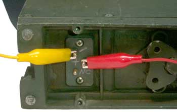
Using a BK Precision 1786 lab power supply, on receive the PRC-104 draws 0.16 Amps and on transmit the current varies a lot with voice peaks, maybe 1.6 Amps average, but the peaks might go up to 3 Amps or more. In CW mode with the key down the current goes slightly over 3 Amps, but this power supply is only rated for 3 Amps. It seems that a large capacitor on the input would be good to handle the peaks.
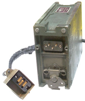
The center pin is Positive. The Negative pin is closer to the ANT SEL switch than the No Connection pin.
Note these pins are on the AM-6874 not the RT-1209.
CY-7875 Battery Case
The CY-7875 Battery box holds two each BA-5590 (or equiv) batteries. Each is connected to supply 30 Volts, so you can actually run the radio on just one battery, but the talk time will be 1/2 what it could be. 5590BA Battery AdapterThis case has a built-in battery charger. It's input is probably a military vehicle "24 Volt" system.Why Two Batteries
The 7875 holds two each BA-5590 batteries, with each BA5590 connected in parallel to provide 30 Volts to the radio. The front of TM 11-5820-919-12 has a couple of warning pages about the BA-5590 and a statement that it contains a 3.2 Amp slow blow fuse. It's my understanding that today the BA-5590 has a 2.25 Amp slow blow fuse. In the specifications table in TM 11-5820-919-12 the Tx current is given as 3.5 Amps at 24.0 Volts. The 24.0 Volts comes from the battery label showing two 12 Volt sections for a nominal 24 Volts. So someone may have mistakenly measured the current consumption at 24.0 Volts when the actual battery voltage is 30. The allowed range of supply voltage is 20.0 to 32.0, consistent with a military vehicle DC supply.
The current is interesting. The specified Tx current (3.5 Amps) is slightly greater than the fuse current (3.2 Amps) in the TM, indicating that two batteries are needed to avoid blowing the BA-5590 fuse. I have used a single BA-5590 without blowing it's fuse, but my Tx times have been very short and so maybe I was lucky with the slow blow aspect of the fuse.
The rechargeable BB-390 and BB-590 do not have a fuse and are capable of large surge currents so a single one would work fine. I had a BB-390, but it exploded during charging.
9 July 2004 - Test using prototype Battery Adapter based on two strings of 11 "AA" cells. When transmitting USB a small number of clicks can be heard in the H-250 handset indicating there are some voice peaks that are pulling the battery below 20 Volts, but when listening on the NRD-545 receiver the voice sounds normal. So the super caps may be the solution to providing high current peaks. Will test that shortly.
Note that when BA-5590 batteries are used, 2 of them are required, and in a similar way if 2 of my prototypes were used, then there would be no low battery warning and the battery life would be greatly extended. There are a couple of diodes that are a part of the battery charging circuitry in the CY-7875 that combine the two batteries. Each battery is connected in series for about 30 Volts and then the two physically seperate batteries are paralleled for more current capability.
The Battery box connector is a MS3102A-10SL-3P and the mating cable connector is probably a MS3106A-10SL-3S.
Don't know if you can use this to power the set with no batteries installed, need to make up the cable and test it.
Each BA-5590 is 170 WH so two of them provide 340 Watt Hours.
CY-7541 Silver Zinc Battery Case
 The original
battery complement was 16 Silver-Zinc 1.86 V cells (30 V)
providing 4.8 AH (144 Watt Hr).
The original
battery complement was 16 Silver-Zinc 1.86 V cells (30 V)
providing 4.8 AH (144 Watt Hr).One of the small ends can be removed to give access to the battery compartment. It's held on by 6 captive screws. The open end is 2.8" x 1.9" and the compartment is 10 7/8" deep.
Other battery complements that have appeared on the internet are:
- 20 each C cells at 1.2 Volts & 4.5 AH /cell = 24
Volts & 108 Watt Hours
- 20 each 5/4C cells at = 24 Volts &
- 40 each 4/3 A cells at 1.2 Volts & 4 AH /cell
= 24 Volts & 192 Watt Hours
This is a little more difficult since there are two strings in parallel.
CY-7875 BA-5590 Battery Case
The "large" CY -7875 is designed to hold two each BA-5590 LiSO2 batteries
or two each BB-390 or BB-590 rechargeable batteries. These
batteries were not available when the PRC-104 first came
out. There is a built-in battery charging circuit that
can be powered from a military vehicle "24 Volt" source.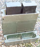
Shown at left are two each 5590BA Battery Adapters installed in the CY-7875 battery box.
 |
 |
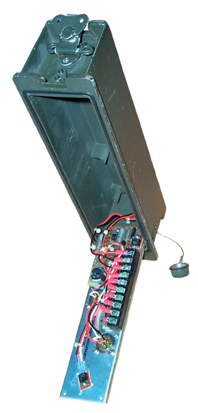 |
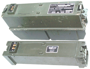
| CY-7541 & CY-7875
side by side photo CY-7541 Rechargable small Battery Box Orig 16 Silver-Zinc 1.86 V cells (30 V) 4.8 AH (144 Watt Hr) Battery Pack 1 Battery Pack 2 |
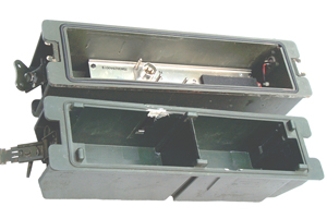
CY-7875 opened
Battery Box NSN 6135-01-080-2886 holds 2 each: BA-5590 or BB-390 or BB-590 |
CY-7875 Inside Battery Charging Circuit 2 each BB-590 {or BB-390?} Box: MS3102A-10SL-3P Cable: MS3106A-10SL-3S |
CX-13032 Battery Charging Cable Assembly 755002A1250
|
The 2-pin connector is a MS3106E12S-3P. The CY-7541 has no charging connector so this cable would be just the thing to charge one. |
CX-13030 Bench Test Cable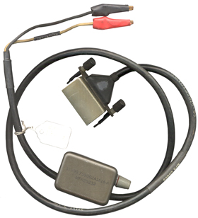 |
This cable has alligator clips on the
input end, a network in line with the cable and the
Hughes box type 3 terminal connector that mates to
the DC input on the AM-6874. The network
consists of over voltage protection circuit and has
an external (Bussmann GMW-5) 5 Amp fuse. The markings are: Shrink label on cable: 87990 ASSY, 755002A1255, MFR 05869 This number matches the p/n in the manuals for the CX-13030 Bench Test Cable. The network box: 87990-755002A1214-A, MFR 25232 White Wire going to Red alligator clip: +26/30 VDC |
Antennas
There are a number of options.
The radio has a 3/8-24 female thread. The AB-129
Spring Base and a 10 foot whip, the AT-271, goes above the
spring base. There is a telephone type push to grab
ground terminal right next to the antenna socket so a
counterpoise can be used. The PRC-47
had the counterpoise wires as part of the base that held
the radio up, but on the PRC-104 the counterpoise must be
connected.
The M-442 could also be used to configure longer whip antennas using MS-116 antenna elements.
AT-271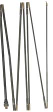 |
AT-271
Fishing Pole Antenna |
| AB-129 Spring
Base |
AB-129 has female 3/8-24 threads at the top and male 3/8-24 threads at the bottom. It's needed to provide some "give" so that the thin walls of the AT-271 antenna don't "fold" when there is a strong wind or other movement. |
| AT-1011 |
The AT-1011
is a vehicle whip that can be configured as a 16
foot or 32 foot whip. |
| AS-2259 |
The AS-2259
is an NVIS antenna system origionally designed for
the PRC-47, but can be
used with many radios be means of adapters. The AB-1241 patio umbrella base, hubcap base was designed for use with the PRC-104, but only using a very short coax cable (non 50 Ohm). |
With an antenna that has a 50 Ohm RF impedance and the internal antenna tuner is disabled, but the VSWR sensor is still checking for a good match.
With an antenna that's NOT 50 Ohms and the internal antenna tuner is active.
Audio Connector
The two Audio connectors take the standard U-229 accessories, U-229 Pin out. When a
modified LS-454 speaker is
connected there's plenty of volume from the stock PRC-104
for indoor use, and maybe for outdoors.The AUDIO connectors are wired:
| Pin |
Function |
| A |
Ground |
| B |
Speaker |
| C |
PTT |
| D |
Mike |
| E |
CW* |
* Instead of connecting to the PTT line, the CW key must be connected to pin E. There are a couple of reasons for this.
One is to support the GRA-71 300 WPM Morse transmission. The PRC-64 & PRC-74 use the same AUDIO connector pin out, and if it has the 6 pin connector, the center pin is +12 Volts to power the GRA-71. When pin E is used for CW an audio tone is injected resulting in a single carrier signal being sent.
The other is that when sending CW from an HF radio in SSB mode if the PTT is used there will be no output because sideband signals are only present when there is some voice modulation.
104 & 104A Manuals
TM 11-5820-919-10HR
TM 11-5820-919-12
TM 11-5820-919-40-1
TM 11-5820-919-40-2
"AN/PRC-104 Ultra Lightweight Manpack Radio" Dec 1974 sales brochure I picked up at HughesTorranceFullerton. "The AN/PRC-104 Manpack Radio is being developed by Hughes Aircraft Company, Ground Systems Group, Fullerton, CA for the U.S. Marine Coops under Contract N00039-74-C-0357." I think they were also working the the TPQ-36 and/or TPQ-37 mortor and artillery gun location systems.
There are no photographs in the brochure, only drawings. The actual PRC-104 looks different in a number of details that are both cosmetic and functional. For example the small battery box is shown with tapered lower ends, both on the cover and inside. The top of the small battery box is shown as a lid that can be opened to allow battery pack installation, but my small battery box has a removable end, not top. There is also an illustration of a chopper where the RT-1209 is located in the cockpit and the amplifier, whether 20, 100 or 400 Watts is mounted near where the HF antenna enters the chopper, about the middle. This implies that an extension cable could be used between the RT-1209 and an amplifier. Another illustration shows AM-6879 that is an audio amplifier, power supply and RTTY converter to be used for vehicle mounting, but not with the 400 Watt power amplifier that makes a GRC-193(). The description of the amplifier antenna coupler says it's a 30 Watt amplifier and the specifications table says 20 Watts output +/- 2 dB (20 Watts + 2 dB = 37 Watts)
The 20 Watt version is called the PRC-104, the 100 Watt base station the PRC-105 and the 400 Watt vehicle mounted system the AN/MRC-138.
The RT-1209 is said to be able to use CW keying at 300 WPM without spurious radiation, but the GRA-71 is not mentioned.
The Antenna Coupler has "a sturdy base for the portable 8-foot whip" which refers to the 3 meter AT-271 fishing pole antenna.. It mentions that both a whip and a coax fed antenna can be attached at the same time, allowing the operator to switch back and forth rapidly to select the best one.
This Dec 1974 brochure mentions that Hughes had already supplied "more than 5,000 AN/PRC-74 Manpack HF radios" for the U.S. Army. That 5,000 PRC-104s were being produced for the U.S, Marine corps and that the HC-191 was identical to the first article PRC-104 with the addition of AM capability for communicating with older military radios.
No where in this brochure do they use the terms RT-1209, AM-6874, AM-6879.
Training Course SS0716 - Single Channel Radio Operator , MOS31C Skill Level 1, Install, Operatre, and Perform Organizational Maintenance on Radio Sets AN/PRC-104 and AN/GRC-213, Part I
Training Course SS0717 - Unit-Level Communications Maintainer, MOS 31V Skill Levels 1 and 2, Install and Perform Unit-Level Maintenance, on AN/PRC-104(A) and AN/GRC-213
PRC-104B Manuals
The 104B has an LCD display, built-in ECCM (i.e. frequency hopping) and the upper audio connector has been replaced by a 19 pin connector labeled CONT for Control.
TM 11-5820-1046-12
TM 11-5820-1046-20P
RT-1209 Receiver Exciter
3/4 View of RT-1209 showing the
interface connector to the AM-6874.
3/4 View of AM-6874 showing the
interface connector to the RT-1209
On the back of the AM-6874 is the
strange Hughes battery box connector.
Interface Connector
There is a 48 pin connector that interfaces the AM-6874 and the RT-1209. This connector supplies DC power into the RT-1209 and from the RT-1209 the low level RF is supplied to the Amplifier Coupler along with digital frequency information to tell the amplifier coupler the radios operating frequency. The pins are designated using numbers at the start and end of 9 rows. In the center there is a hex depression with the corners lettered N, Z, Y, X, W, V.
The RT-1029 has two 4-40 tapped inserts on about 1 9/16" centers and the AM-6874 has a couple of 4-40 screws on about 1 9/16" centers. These could be used to hold a bracket with a mating connector to allow the two units to be separated, like in a helicopter as shown in the Hughes Sales Brochure.
Also see the RT-1444 below.
Mod for 160 meters
PRC-104B 160 M conversion overview
Posted by: "Peter Gottlieb"
Date: Sat Nov 22, 2014 7:08 pm ((PST))
So here's the latest. Two things need to be done in the 1209A RT to enable operation below 2 MHz:
1) The RT has harmonic filters which are selected by logic in a hybrid in the control panel. When the dial frequency is below 2 MHz none of these filters are selected and there is no path for the RF on either receive or transmit. The 2-3 MHz filter must be enabled to operate below 2 MHz; it is fine for 160 M use as it only drops off 1 dB at 1.8 MHz. It does, however, start to fall off a cliff below that.
2) The amp/tuner unit takes MHZ info from the RT and uses this to select ranges for inductance and capacitance. It makes this determination based on logic in a hybrid so cannot be changed. When it is told a 1 MHz range frequency is selected it doesn't operate properly (I did not investigate further as to precisely what it does). There is also logic in the tuner to give a continuous "out of range" error beeping when the frequency selected is under 2 MHz. I decided that rather than modify two devices I would simply modify the MHz information the RT sends to the amp/tuner so as to "fake it out." When a frequency in the 1 MHz range is dialed up I simply tell the amp/tuner it is in the 2 MHz range and the tuner operates in its highest capacitance and inductance range.
What I did was to lift two diodes on the flex board behind the front panel and attach a series of wires. I also picked up ground, +12 volts and the harmonic filter relay coil. Here's a photo of the wires: http://petergottlieb.com/images/prc104/DSC03758.JPG
I ran the wires into the compartment where the modulator PCB is as there is room under it for a small additional PCB with the needed extra components. For the moment, I put what I needed onto a protoboard so the wires are just hanging out: http://petergottlieb.com/images/prc104/DSC03761.JPG
You may wonder what I did in the circuit itself. I needed logic to change a 1 MHz BCD word to a 2 MHz BCD word and also drive an open collector transistor to pull in the filter relay when this is done. I went with Eugene Hertz's suggestion to use an EPROM. There are several things to consider:
1) Due to the diodes, which convert 12 volt logic to 5 volt logic, I needed two 100k pullup resistors on the lines I intercepted (1 and 2 MHz)
2) I used a CMOS EPROM, the smallest I had was a Fujitsu 27C64. Vast overkill, I'm only using 30 locations out of 8,192.
3) No 5 volts is available so I took +12.5 and used a 7805 to make my own. 6.5 is also available but that's a little tight for the old 7805. All I really need is a 78L05 because I'm hardly taking any current but I didn't have one laying around.
4) The open collector drive is very basic: an output of the EPROM drives a 2N2222 through a 1k resistor. It would probably be better to use a higher resistor but that's what was closest at hand. I bet driving that transistor is my biggest current draw.
How does it work? Here is a photo of my counter when in USB CW mode: http://petergottlieb.com/images/prc104/DSC03762.JPG
My frequency is pretty darn close (the counter is referenced to a Rb), something like 0.1 Hz low.
The last step will be to get a 78L05 and build this onto a small board and mount it under the modulator board.
If anyone wants the binary file for the EPROM and the wiring diagram, I'll be preparing those. It is also quite possible to build the logic with a few CMOS chips and it would work the same. Once I get everything finished I'll make a document and put it on my site for anyone to download and otherwise spread around.
There is one thing which is a slight hack, and that is that I don't stop operation below 1.8 MHz. However, the AM station I listen to for weather is there and with 50 kW the degraded sensitivity isn't a problem. If you try to transmit (why?) you will find the output power goes down dramatically below 1.8 MHz as transmit goes through the same filter as receive. I decided to leave that be as I don't have any intention to transmit there and with the power getting so low I'm sure it won't hurt the unit.
One note about the built in tuner: its configuration seems to be mostly designed to tune antennas which are capacitive, or shorter than what should be, such as the whip. My setup is inductive at those frequencies so it doesn't do well, but that has nothing to do with this mod.
Peter
AM-6874 20 (+/- 2 dB) Watt Amplifier/Antenna Coupler
The Antenna select switch has 3 positions
If the wrong External BNC antenna switch position is used you will get a 12 second tune tone followed by an error beeping tone.
- 9 to 16 foot Whip antenna, or a 1/4 wave long wire, where the coupler tunes the antenna.
- External antenna on BNC connector where the coupler tunes the antenna, like the AS-2259 with a non tuned BNC base and a short coax feed line. Could use a cable to separate the RT-1209 from the AM-6874 so the AM-6874 would end up near the antenna feed point improving the antenna match and eliminating any coax loss. This might be a way around my current problem using the AS-2259 with the radio indoors (50 feet of coax away . . this does NOT work.)
- External antenna on BNC connector where the external antenna is near 50 Ohms impedance. No practical length limit on coax feed.
Then just turn the radio off, back on, set the ANT switch to the other BNC position, and key PTT.
Note: the sales brochure mentions that both the whip and a coax connected antenna can both be connected at the same time to allow switching back and forth to choose the best one.
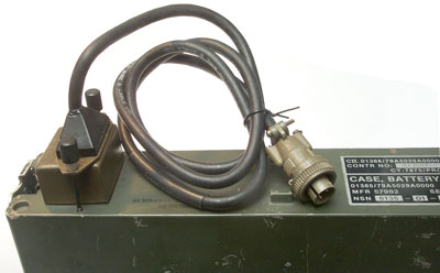
The Hughes 3 contact CD power connector on the AM-6874 and a mating connector on a fabricated cable as used with the AM-7152.
3/4 view of AM-6874
3794941 AUTOMATIC ANTENNA IMPEDANCE TUNER, Lawrence R. Templin (Hughes), Feb 26 1974, 333/17.1 ; 324/619; 324/630; 324/650; 327/236; 333/17.3; 334/47
2 - 80 MHz
Calls:3835379 Detector Circuits for Signal Transmission, Lawrence R. Templin (Hughes), Sep 10 1974 - 2 - 80 MHz
2745067 Automatic Impedance Matching Apparatus, True (na)
3443231Impedance Matching System, Roza (Gulf Genereal Atomic)- analog motor
3509500 Automatic Digital Tuning Apparatus, McNair (Hoffman) - 2 -30 MHz based on MHz and 100 kHz dial setting
3281721Impedance Matching System, Clark (Sperry Rand) -
Calls:3919643 Phase Sensor Circuit, Lawrence R. Templin (Hughes), Nov 11 1975, 2 - 80 MHz
3020529 Reflected Power Alarm for a Variable Power Output Antenna System, Turner (Collins) - vacuum tubes
Calls:4857865 Self equalizing multi-stage radio frequency power amplifier, Arnold L. Berman, Carl J. Hahn, III, Marvin R. Wachs (Hughes), Aug 15, 1989
3366883 Automatic Broad Band VSWR Power Control Griffin (Avco) - turns down power if mismatched
3475703 Coarse Step-Fine Tune Automatically Tunagle Antenna, Collins motor analog
3786355 Radio Frequency Resistance Descriminator having Dead Zone Output Characteric (Cincinati Electronics) -
AT-271A 10 foot whip antenna (the same fishing pole antenna used on the PRC-25 & PRC-77)
AB-129/PR Antenna spring base
AB-1241 NVIS Ground Mount Antenna Base or T1995
AT-984 Fishing Reel Long Wire Ref =MCRP 3-40.3B Radio Operators Handbook, CH 4 - Sloping Antennas
AS-3683/PRC referenced in one of the Antenna Theory sub courses as working with SINCGARS and PRC-104, most likely an error since it's only a 2 foot tape antenna.
KY-872 leg clip Morse code Key NSN 5305-01-067-5388
CX-13030 Bench Test Electrical power Cable
CX-13031 Battery Extender cable
CX-13032 Battery Charger Power Cable NSN 5935-00-231-3180
CX-3515 Coax cable
CY-7542 Transit Case
H-250 Handset NSN 5965-00-043-3463
TM 11-5820-477-12 for the GRA-39 shows the Radio Set Control being used with the PRC-104 in a GRC-193A configuration, but it could be used to remotely control any version of the RT-1209().
Alice LC-2 Pack Components
This PRC-104 was on a corner table at the 2004 meeting of the West Coast MRCG in San Luis Obispo
8465-01-253-5335 MIL-F-43833 81349 LC-1 Field Pack, Medium, Woodland
8465-00-001-6476 MIL-F-43834 81349 Cargo Support Shelf
8465-00-001-6477 MIL-S-43828 81349 Webbing Strap, 1” x 52”, Olive Drab
8465-01-073-8326 MIL-F-43834 81349 Pack Frame w/Straps
Following are replacement parts for the Pack Frame
8465-01-075-8164 MIL-S-43835 81349 Waist Strap
8465-01-151-2891 MIL-S-43835 81349 Frame Attaching Strap 1
8465-01-078-9282 MIL-S-43835 81349 Shoulder Strap, Right Hand
8465-00-269-0482 MIL-S-43835 81349 Shoulder Strap, Left Hand
The RT-1209 and AM-6874 when connected toghther have a front panel that's 12¼" wide and 2¼" high. The depth depends on which battery box is being used. With the CY-7875 (dual BA-5590) battery box the radio is 13½" deep. With the CY-7541 (Samll rechargable) battery box the deepth is 10½". The small battery box version fits with some closure at the top, but even the large battery box version fits the Field Pack well.
GRC-193 consists of (the Harris RF-4000 is all Harris equipment)
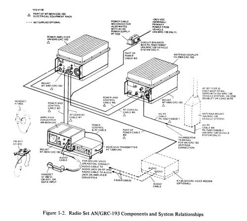
- RT-1209 Receiver Exciter
 |
 |
| Loop current metering tip
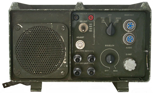
jacks Select 60 ma or 20 ma, TTY On - Off - Spkr On Handset Adjust loop current Audio TTY Key binding posts, Squelch: Off - Max 3 Amp Fuse DC Loop binding posts |
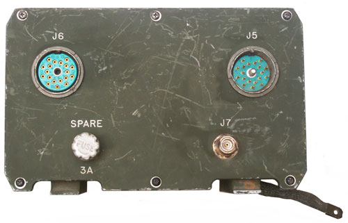
J6 female 19 pin RT
Interface
Con
J5
male
19
pin
DC
in
& PA Ctrl Spare 3 Amp fuse J7 Type-N Jack RT R.F. Ground strap |
 |
 |
TM-11-5820-922-
TM-11-5820-922-40-1
| PIN | TM/EM Number |
Current Change |
Publication Title (partial) |
| 059423 | TM 11-5820-922-40-1 A | AMPLIFIER-CONVERTER, AM-6879/URC (NSN 5820-01-070-1950) |
|
| 059525 | TM 11-5820-922-40-2 B |
AMPLIFIER-CONVERTER, AM-6879/URC (NSN 5820-01-070-1950) |
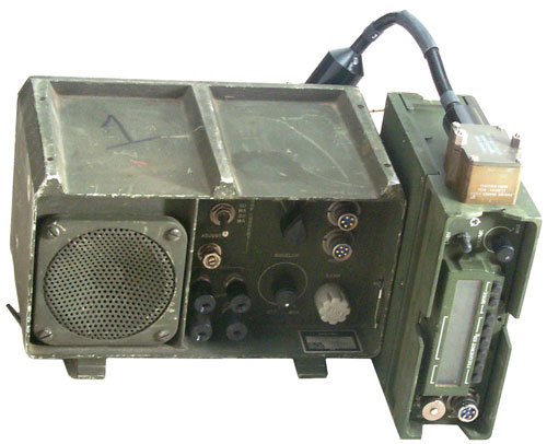
MT-4874 is the side by side mounting tray for the AM-6879 and RT-1209.
RT-1209 <-> AM-6879 Amplifier-Converter Pinout
| Pin |
Description |
| A |
Primary
Power
Return (gnd) |
| B |
Shield
gnd |
| C |
Tune
Start |
| D |
+28
On |
| E |
Sidetone
Enable |
| F |
Keyline |
| H |
Fault |
| J |
ALC |
| K |
Tune
in Progress |
| L |
1
MHz 8 |
| M |
1
MHz 4 |
| N |
1
MHz 2 |
| P |
1
MHz 1 |
| R |
10
MHz 2 |
| S |
10
MHz 1 |
| T |
P.A.
Off/On |
| U |
+28
Battery |
| V |
spare |
| W |
spare |
- CU-2064 Antenna Coupler Harris
NSN 5985-01-050-4869
TM 11-5985-373-40-1
- AM-6545/GRC-193 Amplifier 100 or 400 Watts Harris
NSN 5820-01-186-3699
TM 11-5820-921-40-2- AM-6545A/GRC-193A Amplifier 100 or 400 Watts Harris
NSN 5820-01-186-3699??
TM 11-5820-921-40-1
- MT-6232 Mount
- Whip Antenna
CW-206 Bag, High Voltage Protection Plastic Antenna sleeve, 2 ea. tie down ropes, safety tip, 3 ea. MS-116, 1 ea MS-117 and 1 ea. MS-118 mast sections and the AB-652/GR antenna base.
- RF-4032 Tactical Antenna Siting Kit for up to 200 feet remote antenna location.
- Training Course SS0710 -Single Channel Radio Operator, MOS 31C Skill Level 1, Install, Operate, and Perform Organizational Maintenance on Radio Set AN/GRC-193, Part I
GRC-193A NSN 5820-01-133-4195
- RT-1209 Receiver Exciter
- AM-6879 Audio Amplifier-RTTY Converter
- CU-2064 Antenna Coupler Harris
NSN 5985-01-050-4869
TM 11-5985-373-40-1
- AM-6545A/GRC-193A Amplifier 100 or 400 Watts Harris
NSN 5820-01-186-3699
TM 11-5820-921-40-1
- MT-6232 Mount
- TM 11-5820-924-10-HR
- TM 11-5820-924-13
- TM 11-5820-924-24P GRC-193A
- TM 11-5820-1045-40P GRC-193B(V)1
NSN 5820-01-262-9546- TM 11-5820-1045-20P GRC-193B(V)1
- MK-2462/GRC-193A Installation Kit, Cargo Truck 1 1/4 Ton, 4x4 M882 or M1008A1 CUCV
NSN 5820-01-189-9794
TM 11-2300-475-13&P-1- Mk-2458/GRC-193A Installation Kit, Cargo Truck 1 1/4 Ton, 6x6 M561 Gama Goat
NSN 5820-01-189-979
TM 11-2300-475-13&P-4- Mk-2461/GRC-193A Installation Kit, Utility Truck 1/4 Ton, 4x4 M151, M151A1 or M151A2 (CJ5 Jeep)
NSN 5820-01-189-979
TM 11-2300-475-13&P-3- Mk-2460/GRC-193A Installation Kit, Personnel Carrier, Full Tracked, M113A1 & Carrier Command Post - M577A1
NSN 5820-01-189-9798
TM 11-2300-474-13&P-?- Mk2451/GRC-193A Installation Kit, HMMWV, Car Carrier M998, M1038
NSN 5820-01-227-5842
TM 11-2300-475-13&P-6193() Documents
TM 11-5820-921-40-1
TM 11-5820-921-40-2
TM 11-5820-923-10HR
TM 11-5820-924-10HR
TM 11-5820-1045-20P
TM 11-5820-1045-40P
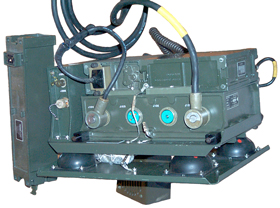
GRC-213 NSN 5820-01-128-3935
 |
 |
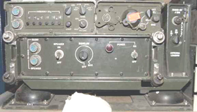 |
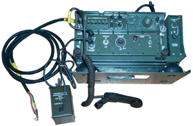
| The GRC-213 is VRC-12
compatible and the Mount fits MT-1029 hole pattern |
VIC-1
connector on rear panel |
Description
There are two functional additions to the PRC-104 to make a GRC-213.
First the AM-7152 adds audio amplification, noise squelch and a VIC-1 connection. Note that the PRC-104 does not have any squelch at all, so this is a big improvement. The AM-7152 also does some DC power conditioning. Not sure what it all is, but there are some very large capacitors in the box. The PRC-104 is designed to run from a BA-5590 which starts out at 30 Volts and goes down. A military vehicle "24 Volt" system might be anywhere between 20 and 30 Volts, so there may or may not be active voltage regulation.
FM 24-19 Chapter 1 shows a retransmission system based on the GRC-213 and VRC-12 series radio, so it appears the main reason the GRC-213 was built is for retransmission applications. In Fig 1-20 they are showing the AM-1780 and the C-2299 and one C-2298 connected to J504, i.e. a commander's connection.
This system was designed to be VRC-12 Series compatible. The mount bolts to the same plate that supports the MT-1029, the VIC-1 and DC power in and out connections are the same as on the MT-1029. The LS-454 is a VRC-12 Series speaker. Any vehicle setup with an RT-246, RT-524 or PRC-25 or PRC-77 on the AM-2060 could easily be converted to use the GRC-213 or become a cross band retransmission system linking VHF low band with HF.
As far as I can tell all the other systems based on the RT-1209 are NOT VRC-12 compatible, i.e. they do not have the VIC-1 interface. This means that they can not easily be used for retransmission. Also note that for retransmission you need squelch to generate the retransmission PTT output, so other audio amplifiers that do not have squelch can not be used for retransmission.
Second the SA-2365 Antenna switch box which is part of the MT-2154 mount assembly that comes with the install kit goes between the existing PRC-104 antenna BNC connector and the actual antenna in use. The Antenna Loading Switch has positions for 2 - 10 MHz, 10 - 30 MHz to an external 15 or 16 foot whip or a Dipole. It's designed to supply some simple fixed tuning (maybe an RF cap.) for a 16 Foot long AT1011 type vehicle antenna. There are two connectors on the rear of the SA-2365, J203 is a BNC(f) and J202 is a Type-N(f). J202 is used to connect to the 15' whip using as short a coax cable as is practicable.
The two ground straps on the shock mount connect to the PRC-104 and to the AM-7152 using a couple of 6-32 x 0.5" screws.
"Vehicle-mounted version of AN/PRC-104 HF manpack radio. Three subsystems: receiver/exciter, power amplifier/antenna coupler, and vehicle mount unit. Vehicle adapter designed to fit footprint of standard VHF/FM series of equipment: VRC-12, GRC-46, RT-524, etc. Power connections and audio intercom equipment fully compatible with FM equipment.
AN/GRC-213A is newer version measuring 406x207x292 mm, weighing 19.5 kg. Data rate of 300 wpm, TTY (FSK) or burst CW. AN/GRC-213B is vehicular or base station version with power output of 100 or 400 W PEP or average.
AN/GRC-213 entered production in 1983 for US Army. October 1983, US Navy, acting as procuring agent, placed $45M order for 1,544 radios. Sept 1987, 448 AN/GRC-213As ordered; in 1988 an option for 94 more was exercised. Production has been completed. " From the Joint Tactical Radio System FACT SHEET.
RT-1209 Receiver Exciter
AM-6874 20 Watt Amplifier/Antenna Coupler
AM-7152 Audio Amplifier/Power Supply
SA-2365 Antenna Switch Assembly
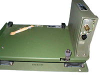
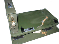
MT-623/GRC-213 shock Mount - has the same footprint as the MT-1029
MT-2154 Equipment Tray
Operation
It would be nice to have more Tx power, but that will not improve the Rx sensitivity. Maybe a GRA-50 dipole is a better choice mounted about 0.1 to 0.1 wavelength above ground for good NVIS propagation.
The AB1241 "small Patio Umbrella" base for the AS-2259 does not like to be driven with 50 feet of coax, it needs a short ( 2 ft.) coax connection to the amplifier-coupler.
The Squelch provided by the AM-7152 allows you to leave the radio on and when there's a "CQ" you can respond. In all cases where I could hear the other station I could work them on the T2FD antenna.
AM-7152 NSN 5820-01-127-5855
DC In -J101 corresponds to J21 on the MT-1029
VIC or crypto interface - J102 corresponds to J22 on the MT-1029
DC out - J103 corresponds to J23 on the MT-1029
J104 is the conditioned DC going to the PRC-104 Battery connection.
Inside the AM-7152 there is a fuse, but I don't see any adjustable link, like the link in the MT-1029. It'll take some Ohm meter work to find out which way the DC is routed.
General Use
Squelch
The AM-7152 connects to the radio using a standard U-229 cable to the AUDIO connector on the radio, thus allowing it to connect to any military radio that has a U-229 AUDIO connector (or probably others with an adapter cable). This would be handy for radios that do not have built-in squelch.VIC-1
Also the AM-7152 provides an easy way to interface a radio with VIC-1 equipment and standard military vehicle power in and out 4 contact connectors.DC Power
The AM-7152 has a regulated power supply putting out about 25 Volts and something over 3 Amps that could drive another radio with an adapter cable.DC Current
The combined PRC-104 & AM-7152 draws about 0.31 Amps from a 30.0 VDC source and about 0.32 Amps from 27.0 Volts.Tx current is around 1 Amp for average speech and just over 3 Amps for CW key down or speech peaks.
CW key down currents
| Nominal Voltage |
Voltage |
Amps |
Watts |
| 30 |
29.3 |
2.6 |
76 |
| 28 |
27.3 |
2.84 |
78 |
| 26 |
25.3 |
3.03 |
77 |
| 24 |
n.g. |
>3.2 |
? |
Note the DC power consumed is about constant with varying input voltage which is consistent with a switching mode power supply in the PRC-104.
The Squelch function is more of an audio attenuator, rather than a turn off the audio type squelch. Maybe there's an adjustment in the AM-7152 that would allow more reduction in audio volume?
The radio is picking up signals generated by my computer. It's not clear if this is because the radio is near the computer (although the antenna is connected by coax, there may be leakage into the DC power wiring.
You would think that a M-80 microphone could be used since the AM-7152 is driving a speaker, but this is not the case. An H-250 handset is still needed so that the operator can hear the side tone that is an indication that the antenna tuner is working and that a signal is getting out. The beep-beep-beep antenna warning tone is quite loud in the speaker, but the short beep to let you know the antenna is being tuned does not show up in the speaker.
Mystery AM-7152
This showed up on eBay 25Jun22 from seller: dxhamstore
in Japan.
| Fig 1 Front Normal AM-7152 Upper left: RT-1209 HF radio Upper right: AM-6874 20 Watt Amplifier/Antenna Coupler  |
Fig 2 Back Normal AM-7152 |
| Fig 1 Front Mystery AM-7152 Upper left: large Mystery box same size as RT-1209 (connectors on front panel) Upper right: small Mystery box same size as AM-6874 (fuse on front panel) 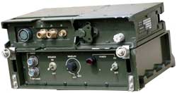 |
Fig 2 Back Mystery AM-7152 Small Mystery box has connectors on rear panel Large Mystery box has nothing on rear panel. Probably there is multipin connector between large and small mystery boxes like between RT-1209 & AM-6874 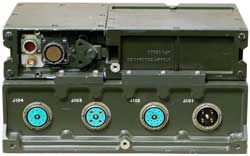 |
RETRANS
AM-1780 & C-2299
The squelch in the AM-7152 enables Retransmission and is supported by J-102 using VIC-1 Vehicle Intercommunication equipment.The CX-4723 Cable connections are:
| Equipment |
Jack |
Jack |
Equipment |
| AM-7152 HF Radio |
J-102 |
J-503 |
AM-1780 VIC-1 Amp |
| AM-1780 VIC-1 Amp |
J-509 |
J-702 |
C-2299 Retrans Ctrl Box |
| C-2299 Retrans Ctrl Box |
J-701 |
J-511 |
AM-1780 VIC-1 Amp |
| AM-1780 VIC-1 Amp |
J-501 |
J-22 |
MT-1029 VHF Radio |
C-2299 Radio Relay Control Box
 |
A simpler way to get a
RETRANS system is to just use the C-2299 directly
between the two radios (without any AM-1780). When the C-2299 has RETRANS set to OFF the other switch selects RT 1 or RT 2 for connection to the handset on the C-2299 providing remote control of two RTs or RETRANS capability. This would allow the GRC-213 to be interconnected with a VRC-64. With the GRC-213 connected to RETRANS with the PRC-77/VRC-64 I could carry a PRC-68 family VHF low band radio around my property and work stations on HF via the GRC-213. Note that RETRANS works both ways so that I could transmit to and receive from the HF station on the VHF low band radio. 14 July 2004 - It's working. When the squelch opens on either the HF or VHF radio the other radio has it's carrier keyed. The audio from the BC-611 is weak in SSB receiving mode, but it's there and can be understood. Note the radio connected to C-2299-J701 is supplying power the the mike amp in the C-2299. So if you want to use a handset connected to C-2299-J703 or J704 the radio connected to J701 needs to be powered. There is no DC path from J702 to the mike amp. For this test I have disconnected the J-3514 from the MT-1029 and am connecting the C-2299 directly to the MT-1099. Also the CX-13065A cable has been disconnected from the AM-2060 and PRC-77 and a CX-4655 interconnects the AM-2060 and PRC-77. Making this an ordinary VRC-64 (non VINSON) VHF radio set. The GRC-213 is connected to the T2FD antenna and the PRC-77 is connected to the OE-254. The NRD-545 is using a VHF Radio Shack scanner monitor antenna and the BC-611 is using it's built in whip. I'm setting the PRC-77 to SQUELCH mode, not RETRANS, since RETRANS is for use with the MK-456. This system uses the squelch breaking to trigger RETRANS through the VIC-1 type connection. |
Note it takes 4 radios to make up a minimal cross band retransmission system. I'm using a BC-611 as the external HF radio, it transmits AM which includes both USB and LSB. When I key the BC-611 I can hear my voice in the GRC-213 speaker. I'm using the NRD-545 as the VHF monitor.
Mk-456 Not Used
The Mk-456 RETRANS Cable is NOT compatible with the RT-1209 audio connectors. On the RT-1209 pin "E" is used for the slow or high speed CW key input and on the PRC-25/PRC-77 pin "E" is used for the RETRANS PTT output. Also the RT-1209 has no squelch and so no RETRANS key signal.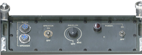 |
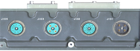 |
| Radio
- Audio from Radio Speaker - Maybe to LS-454 (pins A & E) |
Military
Vehicle
M55181/5 Type Connectors J101 - 4 Plug receptacle - DC Battery In J102 - 18 Socket receptacle VIC-1 Interface J103 - 4 Socket receptacle - DC Battery Out J104 - 8 Socket receptacle - DC to Radio |
Antennas for GRC-213
GRA-50 Dipole
AS-2259 NVIS
Vehicle Whip -? Details
AT-1011 16' or 32' Whip
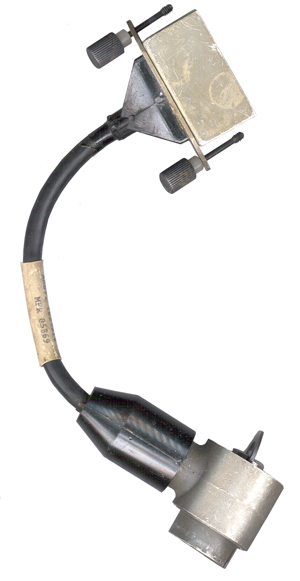
Conditioned DC Power Cable
NSN 5995-01-219-9516
p/n 7550269019
The end mating to the AM-7152 is a standard VIC-1 type MW10M(M)B II connector with 9 male pins.
The other end is the Hughes special DC power connector box that mates to the AM-6874 Amp Coupler.
Shrink Label reads:
ASSY 1623814, MFR 05869
GRC-213 Documents
TM 11-5820-923-10-HR GRC-213
TM 11-5820-923-12 GRC-213
TM 11-5820-1047-12 GRC-213A
TM 11-5820-923-20P GRC-213
TM 11-5820-1047-20P GRC-213A
TM 11-5820-923-34P GRC-213
NSN 5820-01-127-5855
TM 11-5820-923-40
TM 11-5820-923-40P
Installation & Operation Slide Show with sound
FM 44-18 Chapter 4 - Communications (Stinger Platoon Radios)
FM 11-32 Chapter 6 - IHFR
GTA11-03-031.pdf - Operating Procedures IHFR Radio Set GRC-213
TM 11-5820-923-40 Installation Kits:
Mk-2442/GRC-213 Installation Kit Armored Personnel Carrier M113A1
NSN 5820-01-189-9791
Mk2443/GRC-213 Installation Kit, Utility Truck M151A1
NSN 5820-01-189-9792
Mk-2444/GRC-213 Installation Kit, Cargo Truck M561
NSN 5820-01-189-9788
Mk-2445/GRC-213 Installation Kit, Command Carrier Post M577A1
NSN 5820-01-189-9793
MK-2446/GRC-213 Installation Kit Truck M882 or M1008A1 CUCV
NSN 5820-01-189-9789 consists of:
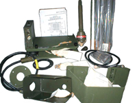
MOUNTING BASE-Provides a shock resistant mount for the AN/GRC-213NSN 5820-01-189-9790
SWITCHING UNIT-Provides impedance matching between AN/GRC-213 and the antenna and enables the AN/GRC-213 to tune to the antenna ANT SWITCHING UNITS A-2365/GRC-213 , DSGN ACT: 80063 , ITEM NO. A3023160 , MFR 54736 , SER NO. 429 US , SPEC: A3023163
ANTENNA-Transmits and receives rf signals ( COMPLETE ANTENNA IS OVER 16 FEET HIGH)
ANTENNA CABLE-Connects the antenna to the switching unit
ROPE-Secures the antenna to the vehicle
ROPE CLAMP-Enables the rope to be attached to the antenna
BATTERY POWER CABLE-Connects the AN/GRC-213 to 24 V dc vehicle battery power
POWER CABLE-Connects the AN/GRC-213 to 24 V dc vehicle power
Antenna Base AB-1322/GR
nuts bolts and washers , ground strap , brackets , antenna sections , antenna tip ball
Mk-2447/GRC-213 Installation Kit General Purpose wheeled or tracked Vehicles
Mk-2542/GRC-213 Installation Kit Cargo Troop Carrier M998, M1038 HMMWV
NSN 5820-?
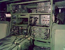
GRC-206 Program Pacer Speak
Designed to be installed in the M151, M113 and the HMMWV. The AN/MRC-144 is a mobile HF/VHF/UHF HAVE QUICK II capable communications facility (AN/GRC-206(V)3) mounted in an M-998 Highly Mobile Multi-Wheeled Vehicle (HMMWV). It provides single sideband (SSB) HF, VHF/FM, VHF/AM, and UHF communications. This system can be remoted up to two kilometers. The HF radio has secure phone patch capability and all radios have secure voice capability. Note the HMMWV has a trailer, probably with a MEP-802A diesel generator, fuel and storage for equipment. The army HMMWV mounted system is called the AN/TSQ-198 Tactical Terminal Control System (TTCS).
FAS AN/TSQ-198 TTCS web page with photos,
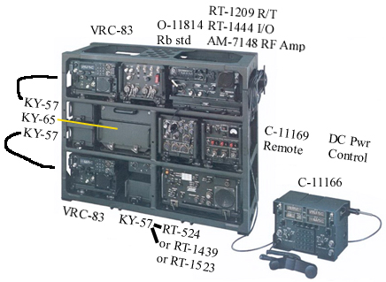
First VRC-83 Aircraft Radio
The VRC-83 combines the manpack RT-1319/PRC-113 dual band
(116-150, 225-400 + 243 MHz guard) aircraft radio with the AM-7176 RF Amp and VRC-83 vehicle
mount. The AM-7176 also contains the digital interface
between the RT-1319 and the C-11169. This RT-1319 is the
UHF-AM frequency hopping radio and so needs the Time Of Day
(TOD). Frequency hopping is not a way to secure crypto
cover for the message traffic, it is an anti jam
measure. For that the KY-57 located just below the radio
is used.Each of the two VTC-83 radios is dedicated to one band. For example this one is the UHF-AM only. There's a couple of reasons for doing that. First, there are a number of UHF aircraft antennas that can be used but very few combined VHF & UHV aircraft band antennas. Second Have Quick frequency hopping is used in the UHF band but it's not clear if it's used in the VHF aircraft band. The O-1814 is only cabled to one of the VRC-83 radios and this is the one it would go to.
The way the C11166 Control is laid out confirms that one of the VRC-83 radios is dedicated to UHF-AM and the other one to VHF-AM. By using the same radio for two different functions there are benefits rather than use two different radios.
O-1814 Rubidium Frequency Standard
The O-1814 Rubidium Frequency Standard maintains the TOD with high accuracy. I think the reason for using a Rb frequency standard in this system while you don't see them in Army SINCGARS installations is the need for UTC accurate TOD. In the army application the net controller can set the TOD and download that time into all the netted radios. Even if the net control time is wrong all the radios will interoperate. But when an aircraft is inbound from someplace far away (the TOD on the aircraft was set at it's home base) the TOD of the aircraft and the Pacer Speak system need to be the same for the radios to interoperate. It is only used on the UHF-AM radio.Second generation and newer UHF-AM radios incorporate Have Quick (Wiki) which includes the ability to transfer a precision Time Of Day over the air. This eliminates the need for an atomic clock in the GRC-206 system.
URC-113 HF Radio
The RT-1209 from a PRC-104 has the RT-1444 remote control add on, or the RT-1209A or B with built in remote interface are used with the AM-7148 Amplifier/Coupler Solid State 150 Watt amplifier works with the RT-1209 or the RT-1444 22.5 to 30 VDC input , 17.5 Amps at 27.5 VDC.Starting with the (V)5 system the PRC-104 has been replaced with the PRC-150.
-------------------- The middle row:
KY-57
KY-65
A KY-65 to support the HF radio.Storage Drawer above KY-65?
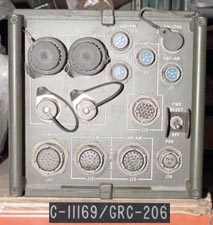
C-11169 Signal
Distribution Unit (SDU)
All the radios are cabled to this box. It can be
connected to the control box using either fiber optic or
twisted pair metallic cable. There will be a cable going
to each of the four radios as well as a power cable.
Note most of these boxes have all the receptacles on the front
panel. The system photo was taken with all the cables
removed. If they were installed you probably could not
see much else.SB-4151 DC Power
Distribution Unit (PDU)
A control panel allowing you to turn off radios not being
used. This system runs from "24 Volt" vehicle power,
Auxiliary Power or a Motor/Generator.----------------------- Bottom row:
Second VRC-83 Aircraft Radio
The same as the first VRC-83 and it's KY-57 is just above the radio. This one is dedicated to VHF-AM operation so only needs an antenna that covers that band.KY-57 for VHF Low Band Radio
The RT-524 and first generation SINCGARS radio, the RT-1439 need an external KY-57 for voice security. The newer SINCGARS RT-1523 has internal voice crypto and so does not need that KY-57.
H-250 Storage Box above KY-57
"That was a handmic box. We stored the H-250's in there so they wouldn't bang around. Other times it was to hold the instruction manual to the pallet. Not quite water tight but it kept a majority of the crud out."
-Charlie-
Army VHF Low Band Radio
First generation systems used the RT-524 radio on the MT-1029. This is a VRC-12 series radio and has no remote control capability. The second generation systems use the RT-1439 first generation SINCGARS radios. I think in the dual radio mount allowing one of them to use an external RF power amplifier. These radios have limited remote control based on the audio tone system which can select a channel number but not setup a channel frequency or other channel setup parameters. The various newer RT-1523 versions have the same remote control capability but also include built-in voice security and so the third KY-57 is not needed.
Different versions of the GRC-206 system have used the different Army VHF-FM radios starting with either the RT-524 or the 10 channel RT-246 (it's not clear to me which) then the RT-1439 that has 6 channels as does the RT-1523. The operator can select which of the preprogrammed channels to use. The implication is that there's some commonality in the channel selection method for the VRC-12 series radios and the SINCGARS radios.
But the C-2742 used with the RT-246 uses a very basic one wire per channel type control whereas the SINCGARS radios use serial data stream via an audio modem. So there must have been a serial to parallel converter in the GRC-206 system when (if?) it was used with the RT-246. If that's the case then the serial protocol in the SINCGARS radios may have been made to the the same one?
--------------------------- Control Box
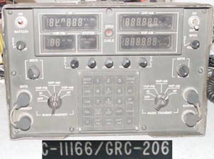
C-11166 Two Operator Control Box
In the lower left and lower right corners are duplicate Audio connectors and a radio selector switch allowing each opertor to choose which radio he will use. It can be mounted between the seats in a vehicle or remotly located using fiber optic cable.
From the t2k Yahoo gaming group:
The AN/GRC-206 (V)1,3,5,6
V1 is model with no crypto and no Have Quick, can be sold to foreign governments
V3 has crypto KY-57 x 3 and KY-65 x 1 and SINCGARS VRC-83 are have quick II (TOD cable)
V5 replaced SDU, PDU, RSC, KY-65 and VRC-46. KY-65 replaced with KY-99 and VRC-46 replaced with SINGARS long range short range combo.
V6 replaced VRC-46 (rt 524 or 246) with dual SINGARS long short combo.
GRC-206(V)1 can be fitted with KY-57 (VHF & UHF radios) or KY-65 COMSEC (HF radios) devices; the GRC-206(V)2 cannot.The GRC-206 mounted in the M-998 hummer is the way we use them for forward air control. In the hummer it is called the MRC-144. The 206 replaced the 155/MRC-107 and MRC-108 (old radio systems).
The 206 is comprised of:
- Top left corner facing the pallet. VRC-83 VHF/UHF AM(RT-1319B/PRC-113 withAM 7148? amp) power output will be 2, 10 or 30 watts. 30 is normal for vehicle ops. Frequency range is 116-149.975 and 225-399.975 Note, in this position it only works in UHF 225-399.975 mode.
- Top right corner. URC-113 HF SSB (RT-1209 with 1444 remote mated with AM -7148 amp). Power will be 150 watts peek single side band. Frequency range is 2-29.99999
- Bottem Left corner is the same as top left corner, except radio only functions in VHF AM mode.
- Bottom Right corner, (currently almost all radio systems are V6's) two SINGARS FM radios. One in bottom position is hooked to amplifier providing @50 watts, top radio is for manpack operations but can be used as the short range radio with hi power being @4 watts. Frequency range is 30 to 87.975 MHz
From a CBD RFQ some GRC-206 parts:
5821-01-408-9471RY CONTROL RADIO SET, P/N, 729450-801
5820-01-411-2903RY CONTROL RADIO SET, P/N 724760-801
5895-01-409-0740RY PANEL CONTROL, RSC, P/N 729456-801
5895-01-408-9101RY CASE, RSC, P/N 729455-801
5998-01-411-2901RY SDU TI AUDIO BOARD, P/N 729446-801
From FAS
- GRC-206(V)3 Comm Pallet. On/off road tactical communications central replaces MRC-107/8. Used by TACP, ASOC, CCT, Combat Comm, and WICP. The AN/MRC-144 is a mobile HF/VHF/UHF HAVE QUICK II capable communications facility (AN/GRC-206(V)3) mounted in an M-998 Highly Mobile Multi-Wheeled Vehicle (HMMWV).
- The communications component of TTCS is an AN/GRC-206 (V4). The primary power source is the MEP-802A diesel generator. It can also be converted to a portable battery powered manpack system.
- GRC-206(V)5 Phase I. Integrates SINCGARS and ANDVT into the GRC-206(V)3. Radios are funded GFE. Includes HF automated link establishment (ALE).
- GRC-206(V)5 Phase II. Continuation of SINCGARS and ANDVT integration into the GRC-206(V)3. Radios are funded GFE.
- GRC-206(V)6 SATCOM. Add enhancements to the UHF DAMA SATCOM radios and integrate into the GRC 206(V)5 pallet. Radios unfunded GFE.
- Next Generation Comm Pallet. Upgrade GRC-206(V)6 pallet to include all similar radios capable of Multiband and Multiwaveform communications.
ASE
SYSTEM
COMPONENT
PART NUMBER
NSN
PAGE NUMBER
AN/GRC-240
ANTENNA
AS-3588/GRC-206
5985-01-110-1051
92
The AS-3588 is the large antenna that is used with the GRC-206 and mounts on a vehicle and covers both the VHF-AM and UHF-AM aircraft radio bands.
System Numbers
NSN: 5985-01-153-7786 - this may be the basic GRC-206
Manuals
Green = Have
Red = Want
The last digit in the p/n dash seems to be the system version number:
GRC-206(V)1 p/n-801 No Have Quick
GRC-206(V)2 p/n-802 No Have Quick
GRC-206(V)3 p/n-803 Have Quick I
GRC-206(V)4 p/n-804 Have Qucik II?
31R2-2GRC206-1 Operator's Manual non Have Quick (V)1 706167-801, (V)2 (707167-802)
31R2-2GRC206-1-1 Operator's Manual VRC-83 Have Quick Supplement (V)3 706167-803 )
Incomplete without 31R2-2GRC206-131R2-2GRC206-1-1 Operator's Manual VRC-83 Have Quick Supplement (V)4 707167-804 )
1 April 1983 no changes
31R2-2GRC206-1-2 Operator's Manual _______ Supplement (
31R2-2GRC206-1-3 Radio Communications System AN/GRC-206(V)6 Supplemental Operator's Manual p/n 707167-600
Incomplete without 31R2-2GRC206-131R2-2GRC206-12 Depot Maintainance Instructions w/IPB (707167-80, 707167-802 )
covers the VRC-91A SINCGARS replacing the RT-246 & KY-99A replacing the KY-38
Includes schematics for the SDU, PDU, RSC FM Bite, R-1444 interface.31R2-2GRC206-12-1 Supplemental Maint Man (707167-803 , 707167-806)
31R2-2GRC206-1TP-1 Operator Instructions
31R2-2GRC206-1TP-2 Operator Instructions
31R2-2GRC206-2 Intermediate Maint Man w/IPB (707167-801 , 707167-802)
31R2-2GRC206-2-1 GRC-206(V)3 Intermediate Maint Man Supplement (707167-803)
incomplete without TO 31R2-2GRC206-231R2-2GRC206-2-1 Intermediate Maint Man ______ Supplement (707167-804)
1 April 1992 no changes
31R2-2GRC206-2-2 Intermediate Maint Man 407L Supplement (31R2-2GRC206-2-3
31R2-2GRC206-2-3 Maintenance Instructions with Illustrated Parts Breakdown,
Intermediate,31R2-2GRC206-12 Techincal Manual,
Radio Communication System AN/GRC-206(V)6 p/n 707167-600
incomplete without TO 31R2-2GRC206-2-1
covers the VRC-91A SINCGARS replacing the RT-246 & KY-99A replacing the KY-38
Maintenance Instructions with Illustrated Parts Breakdown (IPB),31R2-2GRC206-12-1 Supplemental Techincal Manual,
Depot,
Radio Communication System AN/GRC-206(V)6,
p/n 707167-600
31R2-2GRC206-12-2 Supplemental Techincal Manual,
31R2-2GRC206-12-3 Supplemental Techincal Manual,
Maintenance Instructions with Illustrated Parts Breakdown (IPB),31R2-2GRC206-22 AM-7148 Amp-Coup Depot Maint Inst w/IPB (622-6147-001)
Depot,
Radio Communication System AN/GRC-206(V)6,
p/n 707167-600
details on the RFO
NSN: 5985-01-149131R2-2GRC206-2TP-1 Intermediate Maint Man w/IPB
15 Jan 1987, change 3: 22 Dec 2000
31R2-2GRC206-2TP-2 Intermediate Maint Man w/IPB
31R2-2GRC206-2TP-4 Intermediate Maint Man w/IPB
31R2-2GRC206-503 AN/GRC-206(V)5 SINCGARS/ANDVT
31R2-2GRC206-503C N/GRC-206(V)5 SINCGARS/ANDVT
31R2-2GRC206-504 --- title not avail---
31R2-2GRC206-6WC-1 Scheduled Periodic Instpection (V)1 (707167-801)
31R2-2GRC206-6WC-1 Scheduled Periodic Instpection (V)2 (707167-802)
31R2-2GRC206-6WC-1-1 Scheduled Periodic Instpection (V)3 (707167-803)
31R2-2GRC206-6WC-1-1TP-1 Scheduled Periodic Instpection
31R2-2GRC206-6WC-1-2 Scheduled Periodic Instpection 407L Supplement
31R2-2GRC206-6WC-1-3 Scheduled Periodic Instpection Workcards
Radio Set AN/GRC-206(V)631R2-2GRC206-6WC-1TP-1 Scheduled Periodic Instpection
p/n 707167-600
31 Aug 1999
31R2-2GRC206-6WC-1TP-2 Scheduled Periodic Instpection
31R2-2GRC206-7 Installation Manual
Mounting the AN/GRC-206(V)3, AN/GRC-206(V)5 or AN/GRC-206(V)631R2-2GRC206-504 Integration of AN/GRC-206(V)6 SINCGARS/ANDVT
Radio Set into the High Mobility Multipurpose Wheeled Vehicle (HMMWV)
1 June 1999 Change 2
31 Aug 2000
Kit NSN 5820-01-127-3486 p/n 707167-806
How to upgrade (V)3 to (V)6TO 31Z1-407-06 Technical Manual
Depot, Intermediate & Organizational Maintenance
Work Unit Code Manual
407L Tactical Air Control System
16 Nov 1989 change 13
PRC-104 (RT-1209)
31R2-2PRC104-2 Field Maint Inst
31R2-2PRC104-2-1 Supplemental Operation & Maint (RT-1444?)
31R2-2PRC104-4-1 Supplemental IPB
35C2-3-385-11 MEP-025A Gas Gen
GRC-206 System Boxes
RT-1319B VHF 7 UHF AM Aircraft radio
Universal Radio/Remote System Control URSC (guess at words for URSC)
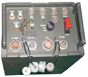
C-11166 2 Op Ctrl Box - has display of the frequency for the HF, VHF, UHF radios and ability to set freq.
Used by two operators (Army, AF).
Photo by Mike Murphy -U.S. ISSUE COMMUNICATIONS EQUIPMENT AND RELATED ITEMSSignal Distribution Unit SDU
C11169 - connects to radio. Can link to the C11166 using fiber or metallic cable.
This is the "SDU" that matches the label on the O-1814.
Photo by Mike Murphy -U.S. ISSUE COMMUNICATIONS EQUIPMENT AND RELATED ITEMS
Power Distribution Unit PDU
SB-4151 (Switch Breaker?)
DC power control box.
Photo by Mike Murphy -U.S. ISSUE COMMUNICATIONS EQUIPMENT AND RELATED ITEMS
Reference Frequency Oscillator RFO
O-1814 Rubidium Frequency Standard and Time Of Day Clock.
Has it's own web page.
Wanted Connection Information: Let me know (2016)
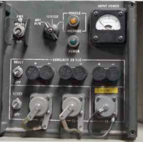
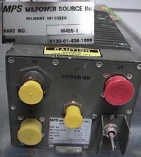
M455-1 Power Supply
NSN 6130-01-436-1099
I think this is a supply that accepts world wide AC power (99 - 262 V @ 47 - 440 Hz)
The outputs are:
#1: 20 - 30 VDC @ __?__ Amps
#2: 8 VDC @ __?__ Amps
#3: 20 - 30 VDC @ __?__ Amps
Photo by Mike Murphy -U.S. ISSUE COMMUNICATIONS EQUIPMENT AND RELATED ITEMS
Note the J1 connector is to supply 8 VDC which is the voltage needed for the PSG-9 Handheld Terminal Unit (HTU) and other small military message computers.
MT-6250B/GRC-206
The photo shows a AM-7239() Dual radio adapter/power supply with the early full size RT-1523 SINCGARS radios. The photo at the top of the GRC-206 section shows a single RT-524 VRC-12 Series radio. The AM-7238 RF Amp is just to the left.
The HF radio is the PRC-138 which has ALE capability. Don't know if the power amp is fast tuning or if it needs to work into a 50 Ohm antenna for ALE.
NIIN:01-486-3196
NSN: 5975-01-486-3196
Item Name: Mounting Base, Electrical Equipment
FSC: 5975
Description: A tray or racklike item designed to provide a supporting surface to which electrical/electronic equipment may be secured when installed in aircraft, vehicles, or other types of mobile equipment. It may be equipped with shock or vibration isolation devices and/or wires, cables, terminal boards, connectors, etc. Excludes BASE, ELECTRICAL EQUIPMENT RACK and MOUNT, RESILIENT. See also RACK, ELECTRICAL EQUIPMENT.
Commercial and Government Entity Code (Supplier Data):
Parts Hangar
partshangar.com
9438 US Hwy 19 N. #311
Port Richey, FL 34668
Ph. (727) 619-7700
Fax. (727) 255-5042
37695 RAYTHEON COMPANY
1010 PRODUCTION RD
Fort Wayne, IN 46808
260-429-4046
Reference Numbers (Part Numbers):
MT-6250B/GRC-206
812084-803
Required Description:
Ht 31"
Depth 16"
Width 38"
Weight Minus Equip 20 Pounds
AS-3588/GRC-206
VHF-AM & UHF-AM Antenna
8 Nov 2007 GRC-206 at Mike Murphy's Surplus
He has set a PRC-138 in the upper right corner instead of the HF radio.
In the lower right he has set a couple of RT-1523 SINCGARS radios, but without the A/PS & Mount.
This is close to a GRC-206(5) system but the O-1814 was only in the GRC-206(3) system.
Raytheon Systems Company, Fort Wayne, Ind., is being awarded a $24,000,000 firm-fixed-price contract to provide for various quantities of components for the AN/GRC-206(V)4G communication system applicable to a range of ground vehicles, including the High Mobility Multipurpose Wheeled Vehicle and the M113 Armed Personnel Carrier. This effort includes support services, site survey, installation services, technical support and data. This effort supports foreign military sales to Greece and Jordan. There was one firm solicited and one proposal received. Expected contract completion date is ten each per month starting 12 to 14 months after receipt of order. Solicitation issue date was Aug. 6, 1998. Negotiation completion date was Dec. 9, 1998. Sacramento Air Logistics Center, McClellan AFB, Calif., is the contracting activity (F04606-99-D-0018).
ROMAD - Radio Operator Maintainer And Driver - Tactical Air Control Party (TACP) "Death on Call"URC-113
A part of the GRC-206 system consists of the :
RT-1209 receiver/exciter
RT-1444 Remote control add on
AM-7148/GRC-206 150 Watt amplifier coupler (NSN) 5985-01-149-1437,
TO 31R2-2GRC206-22 Maintenance Instruction with Illustrated Parts Breakdown, Depot, Amplifier-Coupler, AM-7148/GRC-206, Part No. 622-6147-001, NSN 5985-01-1491, 15 Jan 1987, Ch 3 - 22 Dec 2000 + some hand changes. Need to study this to see if there's any RT-1444 information.
GRC-206 Fact Sheet.doc -
RT-1444 Remote appliqué
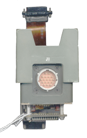
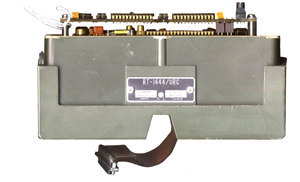
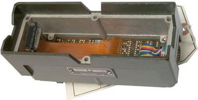
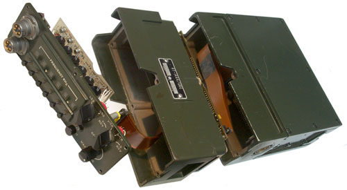
The RT-1444 is a remote controllable version of the manually operated RT-1209. Note that the RT-1209A has a built in remote control capability by means of the CONT connector located above the the single AUDIO connector. The unit pictured here is inserted between the front panel and the main body of the RT-1209 to make the resulting radio into an RT-1444/PRC-104. J1 is the 18 male pin ITT Cannon connector that has an internal 16 wire ribbon cable connecting to it. Most of the box is hollow and from the cavity there is a ribbon cable with a 18 + 17 + 16 three row "D" shaped connector with 51 male pins. On the other face there is a similar 51 pin connector with sockets. Thus the RT-1444 can be inserted between the front panel and the RT chassis. There are a couple of multilayer printed circuit boards and a number of large ICs, probably a microprocessor, RAMs and PROMs.
Jan 2009 - The Remote was made to allow the RT-1209 to be used with the GRC-206 (URC-113 uses the AM-7148 RF Amp) or the GRC-193 (uses the AM-6545 RF Amp). In either case the RF amp needs the MHz frequency information from the RT-1209. Also the GRC-206 allows remote setting and read back of the radio frequency. Later GRC-206 systems used the PRC-138 to get ALE capability and the RT-1444A adapter box similar to the RT-1444 that had ALE capability was aimed at this application, but I don't think it was chosen.
The RT-1444A has had the internal PCB removed and replaced with a new set of boards and has ALE capability. The 1040 upgrade kit was sold by NSG Datacom (took over the Frederick Electronics product line) to the Swedish Army for use in PRC-104 systems. I don't think the AM-7148 RF Amplifier/Coupler can tune the antenna fast enough for ALE, although if used with a matched antenna, like the B&W terminated folded dipoles might work if the band switching time is short enough.
18 Pin J1 Interface connector
Side View
Install RT-1444 between Panel and Chassis of RT-1209
6-32 Pan head Philips screw self capture longer than 2.53" (not a 2.5")
Notice connector on RT-1209 chassis for amplifier.
The RT-1444 remote connector is on the oppsite side.
The long screws installed to hold RT-1444.
Now to remove them all and put on the flat washers.
I have some extras let me know if you want to buy some.
RT-1209 + RT-1444 + AM-6874
Wanted to see if the AM-6874 can still be used when the RT-1444 is fitted, and the answer is yes.
The following entry was found on Commerce Business Daily:
The RT-1444 shown in the above images is labeled:RT-1444/URC
Ser: AE0283 812130-801
F04606-81-C-0017 Mfr: 37695
Magnavox U.S. Ft. Wayne, Ind
The Tobyhanna Army Depot Process Tag has:
National Stock Number: 5895-01-140-8315
Serial Number: AE0283
Nomenclature: CCA
the inspection stamps are dated 18 Nov 99
and on the back:
Tested/Repaired in Accordance with:
31R2-26RC206-2 Table 5-1A
The Faraday bag is labeled:
5895 01 140 8315
CAGE p/n 812130
MGX-12/99 B 1 ea.
RE/Pack DLA/TP
CC-A
Ser No-AE0283
The outer cardboard box has the same info and TYAD RWKD & TSTD 11/99
It looks like the contact was in 1981 and then in 1999 Tobyhanna Army Depot made some modification, tested and repacked the unit.
CBD RFQ:
Item 0001 NSN 5895-01-140-8315ZX P/N: 812130-801, INSTALLATION KIT FOR RT-1444.
CASE MODIFICATION FOR RT-1209. E/I AN/GRC-206(V). ECO 87C0508 APPLIES TO THIS ITEM.
So maybe the modification done at Tobyhanna Army Depot was something to support the use of the RT-1444 with the GRC-206 system.
J1 Pin Out
Mating cable connector is NOT MS3116F-14-18S. This connector does not work since two of the standard keys do not match the RT-1444. Some work with a Dremel grinder on the connector (removing the two narrow out of place keys) will NOT allow it to fit.
The correct mating connector may be the MS 27484T-14F-18S.
The connector for the MT-6250B/GRC-206 is a MS 27484T-14B-18S.
But the rotation of the main key (the minor keys remain the same w/respect to the pins is the "A" rotation. That means the part number ends with A such as:
MS27484E14B18SA
See the Part Builder.
# following a signal line means the inverted (not) form of the signal. This was probably done to make the logic simpler.
Pin
Description
Wire
color
DIP
pin
T
Shield Ground
Blu
1
R
Remote Select #
Yel
2
K
RT-1444 Status
Red
3
J
RT-1444 Status #
Blk
4
U-nc
nc
nc
nc
L
RT-1444 Clock
Blu
6
F
RT-1444 Control #
Yel
7
E
RT-1444 Control
Red
8
N
Gnd
Grn
9
P
Gnd
Org
10
H
Gnd
Brn
11
A
Spare
Wht
12
B
Spare Vio
13
C
Spare Grn
14
G
Spare Org
15
S
?
Brn
16
D-nc
no connection
M
RT-1444 Clock # ?
Gry
5
DIP pins 1, 9, 10 & 11 are connected toghther (grounds).
Connector pin M seems to be out of order with the DIP numbering system so I ass-u-me that DIP pin 5 is the RT-1444 Clock# signal that my first source showed on connector pin U.
Pin R - Remote Select - probably chooses between an active front panel and remote control. Since this is the inverted signal, an open means not-remote and a grounded pin means remote. That way when no cable is connected the radio works from the front panel. I was told that the remote cable just has a jumper between "R" and ground. A better way would be to allow a remote computer decide to allow the radio to be in remote or local mode.
Pin L (clock) & Pin U (/clock) probably are for serial data streams "Control" and "Status", where "Control" most likely means commands to the RT-1444 and "Status" means data coming from the RT-1444, like frequency, etc. and maybe error codes.
The other connectors that interface external to the RT-1444 are the male and female 51 pin interfaces to the RT-1209 front panel and the RT-1209 main chassis.
1040 ALE Modem would require the RT-1444 remote so that the frequency of the PRC-104 could be controlled. Or maybe the other adapter that's similar to he RT-1444 which is an ALE adapter?
It may be possible to send and receive ALE signals, but without changing RF frequency using the Data T/R mode. See photo army mars.
TM 11-5820-40-1 Table 1-4 Cable W2 RT Control has pinout information that's related, but it uses a parallel (one wire for each front panel button) protocol, meaning that somewhere else there's a serial/parallel converter.
RT-1444A ALE & Remote appliqué
This unit is physically the same as the RT-1444 and is installed between the front panel and the main radio chassis in the same way.
It provides ALE capability. It uses the KGV-10 hopping controller that's used in the SINCGARS radios. The first SINCGARS radios (Wiki) were built in the 1983 time line with the RT-1439 produced in 1988. So it makes sense that both these radios use the same frequency hopping control IC.
From the PC control software:
'-------------------------setup comm port--------------------------------------
'Set the size of the communications buffer to 32K
Com = 16384 * 2
'Open communications port 1. It's handle is #comm.
'If you need to change to com 1, this is the line to modify
open "COM1:9600,e,8,2,ds0,cs0,rs" for random as #comm
'-------------------------initialize, options, set variables--------------------
Meaning:
rs RS suppresses RTS (request to send)
CS[n] controls CTS (clear to send)
DS[n] controls DSR (data set ready)
CD[n] controls CD (carrier detect)
LF sends a line feed at each return
PE enables parity checking
n is the number of milliseconds to wait (0-65535) for that signal before a device timeout error occurs. Defaults are: CS1000, DS1000, and CD0. If RS was specified then CS0 is the default. If n is omitted, then timeout is set to 0.
For the ALE version the connector pin-out is:
# following a signal line means the inverted (not) form of the signal. This was probably done to make the logic simpler.
Pin
Description
RS-232
Wire
color
DIP
pin
T
Shield Ground
Gnd (5)
R
Status out
Rx data (2)
K
RT-1444 Status
Tx data (3)
J
SQLIND
U-nc
nc
L
Rx Test Audio Out
F
Tx Test Audio Out
E
SDU Cable Installed
N
Chassis Gnd
P
Spare
H
Shift Clock
A
Orderwire/serial in
B
Orderwire/serial out
C
PC Terminal Installed ?
G
Control to Interface Test Only
S
?
D
Orderwire CTS
gnd (enable rmt)
M
Latch Clock
PS The CONT connector on the from of the prc104B is for the hop device
The above info thanks to John Gray.
C-11525/G Frequency Hopping Controller
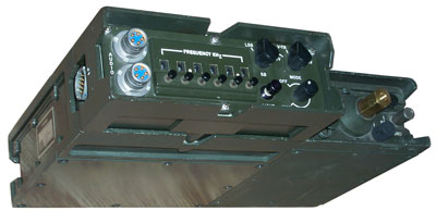
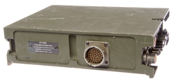
This is the frequency hopping controller that can be cabled to the CONT connector on the RT-1209A (there is no CONT connector on the RT-1209).
aka Short-Term Antijam (STAJ).
Front Panel items are left to right:
19 male pin Control connector (to RT-1209A Control connector)
ECCM (Electronic Counter Counter Measures) Switch: Non ECCM, Set, Zeroize (Pull)
An LCD
Light Push switch
Display Push switch
Switch: Up, <center offr> Dn
Switch: Clear, Enter
U-229 Fill Connector
2.5" high same depth and width and the combined RT-1209A & AM-6874.
I've heard that the AM-6874 and the AM-7148 work with ALE but not AM-6545 used in the GRC-193().
Communications, Actions Needed to Ensure Advanced High Frequency Radios Interoperate, March 1989 the Army and Air Force are not coordinating their anitjam, ALE and modem efforts. Mentions ARC-190,Enhanced Miniaturized Terminal MD-1230 (Radio Wiki: Modem Sagas) (MIL-STD 188-110 change 2), says the STAJ applique performs antijam and ALE functions. Navy High Frequency Antijam Program was terminated. ALE standard was completed in 1988.
From Institute of Electrical and Electronics Engineers, Inc., 1988 - Spread spectrum communications - Figure 1 is a picture of the 5254B(V6). A tactical version of the MD1230 (Figure 2), is being developed for the Army which includes integral comsec and LPC-10 voice capability.
Controller, Receiver-Transmitter
C-11525/G
1698125-100 FSCM No 95869
Contract No DAAB07-82-G-J220-0001
Ser No. 0021A
MFR 05869 US
Backup uses 2 series connected BA-5567
The same battery used in night vision devices.
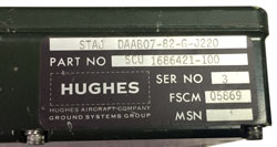
STAJ DAAB07-82-G-J220
p/n: SCU 1686421-100
s/n: 3
FSCM: 05869
Programmer/hop set loader?
Very similar appearance to the EPLRS.
RT-2000 Receiver-Transmitter
This is a combined RT-1209 and the RT-1444 all in one box so on one side it has the connector to go to the RF Amp and on the other side the connector for the URC-113/GRC-206. It has the same battery box connector on the bottom to make a PRC-104 manpack radio.
Label:
RT-2000
Receiver-Transmitter
Collins Telcom Products Drv
Rockwell International
Cedar Rapids, Iowa U.S.A.
Controls and Indicators
Two 6-pin U-229 type AUDIO connectors
Function Switch: OFF, RCV, MAN, A, TEST, unmarked, unmarked, unmarked
Left-Right navigation knob (continuous rotation in steps)
Up-Down navigation knob (continuous rotation in steps)
VOL knob in steps
LIGHT momentary push bottom
LCD with labels a top: VOL, MODE, FREQ, SQL, PWR
If you have any info on this please let me know.
The date codes on most of the chips show 1982.
Photos
Fig 1 Front Panel
The Function switch continues to turn past TEST
a few clicks (maybe defective) Pressing LIGHT
turns on a couple of lamps.
Fig 2 Left Side w/ URC-113/GRC-206 Remote conn
Fig 3 Right Side w/ RF Amp-DC power conn
Fig 4 RT-2000 with AM-6874 Front
Fig 5 RT-2000 with AM-6874 back
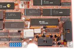
Fig 6 Inside bottom of digital board
Fig 7 Top of digital board
Fig 8 Top of 2-layer stack
Fig 9 Bottom of 2-layer stack IF subsystem
McCoy 42.995 MHz can osc & Collins Mech Filter
Fig 10 Top of bottom board
Power supply to the front & audio to the back
Maybe RF in central can?
The bottom board can be lifted out.
Fig 11 Top of digital board showing clipped resistor
just above notch at bottom center of photo.
-------- the above radio is dead ----- the below radio receives but does not transmit ------
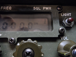
Fgi 1 Function: Test
Volume: bar graph
Mode: USB, UD = LSB/USB, UD/LD
88.8888
Freq: FAULT
Squelch OFF, CW
Power: 8
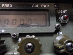
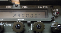
Fig 2 Function: A
Full Vol, USB, 29.0000, On, 3
Fig 3 Function: ?
squelch on, pwr: 3
Fig 4 Function: ?
Squelch on, pwr: 1
Fig 5 Function: Man
USB, 29.000, On, :
Fig 6 Function: Man
Full Vol, USB, 29.000, Off, :
Fig 7 Function: Man
Full Vol, USB, 2.0000, Off, :
Fig 8 Function: RCV
black screen
Voice Security
KY-65
FM 24-19 Section IV has info about using the KY-65, 2 ea. BA-1372 HUBs, CX-13168 cable between the RT-1209 upper AUDIO connector and the KY-65 RADIO connector. Z-AKE is an AC/DC power supply for the KY-65. CX-13211 cable between the KY-65 AUDIO connector and the AUDIO connector on the AM-6879 Ampl;ifier-Converter. Handset to AUDIO connector on KY-65.
In a vehicle installation the cable from the J-4885/GRC Junction Box goes to the speaker connector on the Amp-PS. The H-250 handset connects to the J-4885 HANDSET connector. An LS-454 Speaker connects to the Speaker connector on the J-4885
Less than 10.2 volts causes a battery fail condition. This is consistent with a 10 to 15 Volt range for a "12 Volt" supply.
The KY-65 uses the Parkhill algorithim. If someone talks too fast then the message gets garbled. This is because the output needs to have a narrow (3 kHz) bandwidth to work with HF radios. A fast talking person will exceed 3 kHz bandwidth.
It think this system divides the 300 to 3,000 Hz voice band into 9 sub bands each 300 Hz wide. The signal in any of the 9 bands can be changed to any of the other bands either as is or inverted. So there are 18 things that can be taken 9 at a time or 18!/(18-9)! = 17.6 billion. Note that the key is a fixed permutation of the sub bands and does not change with time like the more modern voice encryption systems, so no date - time input is needed. It may be related to U.S. patents 2183248 & 3012098 assigned to Bell Labs?
KY-65 controls: & Indicators
INT BAT / AUDIO / EXT BAT
OFF / ZEROIZE / STANDBY / ON - standby uses the external DC power for keep alive, saving the HUB batteries.
PLAIN / CIPHER
VOLUME
FILL SELECTOR
DELAY OUT / DELAY IN / SIG CLEAR
HF / NON HF
Amber Light
PS Voltmeter
Uses two each BA-4386 batteries.
The KY-99 Miniterm replaces the KY-65 for voice security.
Cables
CX-13168
CX-13211
NESA N00140-92-C-AB15, RT-1209 to KY-99, 29357-46923-202014-24
The RT-1209 end goes to an AUDIO connector on the RT and has a 5 contact U-229 type connector, except it looks to be TEMPEST rated. KY-99 end that attaches to the RADIO connector is a MS27467T11B35S. This is a 13 Socket connector. This cable has a 1992 contract date, so the KY-99 was supported at least this early.
KY-99 RT-1209
1
A
2
B
3
C
4
A
5
D
6
A
7
n.c. 8
n.c. 9
n.c. 10
n.c. 11
n.c. 12
n.c. 13
n.c.
