AS-2259/GR NVIS Antenna
and NVIS in General
5980-00-106-6130© Brooke Clarke, N6GCE 2003 - 2016
 |
 |
 |
| Carry
Bag |
Installed |
Top |
|
|
|
| Carry
Bag |
Installed |
Top |
The AS-2259, NSN 5980-00-106-6130, is rated for 2 to 30 Mhz and up to 1,000 Watts. The antenna is said to be compatible with radios that typically use a 15 foot whip antenna. Also known as the Collins 637K-1 antenna or Telex Wireless Model 1990.
Military H.F. radios typically use a vertical whip antenna, like the AS-1320 on the PRC-47. The whip works against ground by means of a number of radials. The main lobe is at right angles to the centerline of the antenna or parallel to the ground. This works well for distances up to about 70 miles (ground wave) [FM 24-19 says 10 miles for a man portable radio and 15 foot whip] or for very large distances corresponding to one or more hops off of the ionosphere (greater than 300 miles). If the H.F. radio is located in a valley or jungle these whip antennas do not work very well and so the Near Vertical Incidence Sky wave antenna was developed.
An NVIS antenna has it's main lobe pointing straight up (or nearly so). The idea is to bounce the signal off the ionosphere and have it reflect straight down. This provides a strong signal out to 200 to 300 miles in all directions. This is the largest coverage area you can get with a single receiver transmitter without a repeater. Note that squad radios operating in the 30 to 88 MHz VHF low band are designed NOT to have long range to prevent the enemy from eavesdropping. Classical H.F. radio using antennas on high towers is designed to provide long haul communications. NVIS is ideal at providing solid communications that fill the gap between these two modes, out to a radius of 200 ot 300 miles.
The ideal height would be 1/4 wave above a metal surface. The would put the main lobe straight up. If you don't have a metal plated back yard but instead have dirt for ground the depth of the effective ground plane will be some distance below the surface. In sandy or rocky areas that may be very far down, in which case the antenna can be laid on the surface or buried.
When the height of the antenna is lowered the dirt acts as a resistive shunt on the antenna lowering the transmit efficiency and also lowering the receive noise.
The "D" layer gets charged by the sun on a daily basis. So near noon it has the most charge. The "D" layer has a resonance around 1.6 (? memory) MHz and that's where it has the highest loss. The farther away from 1.6 Mhz the less D layer adsorption there is. So NVIS is not a mode that will work for the AM broadcast band. This is also why most military field portable HF radios have a frequency range like 2 - 12 MHz. The lower end is limited by the D layer and the upper end is limited by the NVIS mode since it's very difficult to put a dipole up a 1/4 wave in the field.
When radials are used with a whip antenna the coupling to the Earth is lossy. Antennas that are balanced like a dipole have higher efficiency because they do not suffer from ground loss. NVIS antennas are about an average of 10 feet off the ground and do not suffer from ground losses. Some NVIS antenna systems, like the Eyring, operate a foot or so off the ground.
4743917 Apparatus and method for a portable roll-out antenna (Eyring Research Institute, Inc.), May 10, 1988, 343/877 ; 242/388.6
4755824 Hardened coupling device and method, (Eyring Research Institute, Inc.), Jul 5, 1988, 343/719 ; 174/50
4829310 Wireless communication system using current formed underground vertical plane polarized antennas, (Eyring Research Institute, Inc.), May 9 1989, 343/719 ; 343/847
4839661 Guided wave antenna system and method, (Eyring Research Institute, Inc.), Jun 13, 1989, 343/719 ; 343/847
4861289 Hardened electrical connector, (Eyring Research Institute, Inc.), Aug 29, 1989, 439/792 ; 174/87; 439/7904750001 Portable roll-out antenna system and method, Brian L. Grose, Craig M. Huntsman (Eyring Research Institute, Inc.), Jun 7, 1988, 343/877
Calls:4825224 Broad band impedance matching system and method for low-profile antennas, Brian L. Grose, Orval N. Skousen ( Eyring Research Institute, Inc), 343/860 ; 343/822 -
1894244 Antenna Reel, Jan 10 1933, -
2161044 Antenna Reel, (Heintz & Kaufman), - Aircraft
2574733 Tape Antenna System, (Tele-Tonic Radio Corp), -
2834012 Variable Length Antenna, (Army), - tanks, cars, trucks, etc.
2842768 Extensible Antenna, (Stirling Precision Inst Co), -multiple tapes combine
3400402 Wire Antenna Extensible Along Calibrated Support Means, (Collins) - GRA-50?
3577148 Portable Reelable Dipole Antenna having Frequency Calibratied Dial (Collins) - Collins TD-1, 637T-2
Calls:
714246 Nov 1902
760463 May 1904
795762 Jul 1905
1101533 Jun 1914
1123119 Dec 1914
1220005 Mar 1917
1303729 May 1919
1303730 May 1919
1315862 Sep 1919
1316188 Sep 1919
1322622 Nov 1919
1349103 Aug 1920
1349104 Aug 1920
1373612 Apr 1921
1377129 May 1921
1387736 Aug 1921
1395454 Nov 1921
1424365 Aug 1922
1429240 Radio Signaling System Sep 1922 - buried electrodes
1510799 Loop Aerial, Oct 1924
1530129 Radio Signaling System, E.H Loftin & H.H. Lyon, Mar 1925 - includes wire buries inside pipe
References:1894244 Antenna Reel, Jan 10 1933, - Jan 1933
760463 Marconi, May 1904
771819 De Forest Oct 1904
795762 Garcia July 1905
1101533 De Forest July 1905
1220005 Rogers & Lyon March 1917
1303730 Rogers May 1919
1322622 Rogers & Lyon Nov 1919
2161044 Antenna Reel, (Heintz & Kaufman), - Aircraft Jun 1939
2225668 Method and Apparatus for Logging Drill Holes, (Union Oil), Dec 1940
2574733 Tape Antenna System, (Tele-Tonic Radio Corp), - Nov 1951
2712602 Reflection-free Antenna, (Ericson), Jul 1955 - log periodic?
2834012 Variable Length Antenna, (Army), - tanks, cars, trucks, etc. May 1958
2842768 Extensible Antenna, (Stirling Precision Inst Co), -multiple tapes combine Jul 1958
2989621 Fire alarm System using a Plural Oscillator Radio Transmitter (Jennings Radio), Jun 1961 - wireless fire box system
2992325 Earth Signal Transmission System, Space Electronics Corp), Jul 1961
2998516 Subsurface Relay Station Apparatus, (Space Electronics Corp), Aug 1961
3183510 Underground Loop Antenna, (Deeco Electronics), May 1965 - Nuke hardened
3212093 Center-fed Whip Antenna, (Army), Oct 1965 - works after bening broken below the feed point
3215937 Extremely Low-frequency antenna, R.L. Tanner (CDC), Nov 1965 - array for use below 1 kHz
3346864 Underground Antenna, (Northrop), Oct 1967 - blast proof
3400402 Wire Antenna Extensible Along Calibrated Support Means, (Collins) - GRA-50? Sep 1968
3435457 Underground Antenna, (Army) Mar 1969 - blast proof
3577148 Portable Reelable Dipole Antenna having Frequency Calibratied Dial (Collins) - Collins TD-1, 637T-2 May 1971
3594798 Underground Antenna, (Westinghouse) Jul 1971 - nuke hardned
3705407 Radio Surface Wave Antenna, (SRI), Dec 1972 - looks like above ground oil pipeline
3775772 Ultra Hard Communications Antenna (Air Force), Nov 1973
3803616 Sub-surface Radio Surface Wave Launcher (SRI), Apr 1974
3867710 Communication System (IT&T), Feb 1975 - floating submarine antenna
3967201 Wireless subterranean signaling method Jun 29, 1976 - 1000 meters loop down a borehole
4511898 Terminated inverted V antenna with matching transformer Apr 16, 1985 - 1.8 to 30 MHz 110' long x 35' center mast
4687445 Subsurface antenna system (RCA), Aug 18, 1987 - survivable
The AS-2259 was designed for light weight single man carry and is NOT optimized for NVIS performance. The electrical performance has been traded for weight. The NVIS mode can only be used at the low end of the H.F. frequency range around 2 to 9 MHz depending on the ionosphere.
The GRA-50 is a NVIS type dipole made for use with the GRC-19 vehicle mounted HF radio.
In Vietnam the enemy H.F. operators were using NVIS antennas, probably for the reasons stated above, and the loop antennas on the PRD-1 direction finder receivers would not give good bearings on signals coming almost straight down. (It seems that someone would have made an Adcock antenna attachment for the PRD-1 to counter this problem?)
The term NVIS was coined either late or just post Vietnam era, but the mode was understood and used much earlier.
My house is located in a forest canyon with 80 foot high trees all around. By using NVIS I can communicate with stations out many hundreds of miles, but it's difficult to get a "low angle" signal out either on HF or on VHF-UHF.
The Harris PRC-150 (replacement for the PRC-104) lists the following antennas:
The Antenna System 2259 consists 7 mast sections, each about 2 feet long that are 50 Ohm coax hard lines. There's a male end and a female end. At the top there are 4 antenna elements that are used as guy lines to support the antenna. The short antenna element is 2 * 24'10" long and the long antenna element is 2 * 36'10" long. A short and a long element are connected to the outer (ground) side of the mast/coax and the other short and long elements are connected to the mast center (hot) conductor. The AS-2259 does not include the base adapter. There are a number of different base adapters to connect the AS-2259 to a number of different radios or to use it as a stand alone antenna.
A half wave dipole that's 49'8" long (15.1 meters) has a self reasonant frequency of 9.9 MHz and a half wave dipole that's 73'8" (22.5 meteres) long has a self reasonant frequency of 6.7 MHz. These get transformed by the 14 foot long 50 Ohm impedance mast.
Sewn on the inside of the canvas carry bag are the Instructions for Installation and a Parts Breakdown. I've made these into a pdf document AS2259Ins.pdf about 290 kB..
Harris makes wersions of this antenna called the RF-1936 (same as AS-2259), RF-2236 and the double sized RF-2238
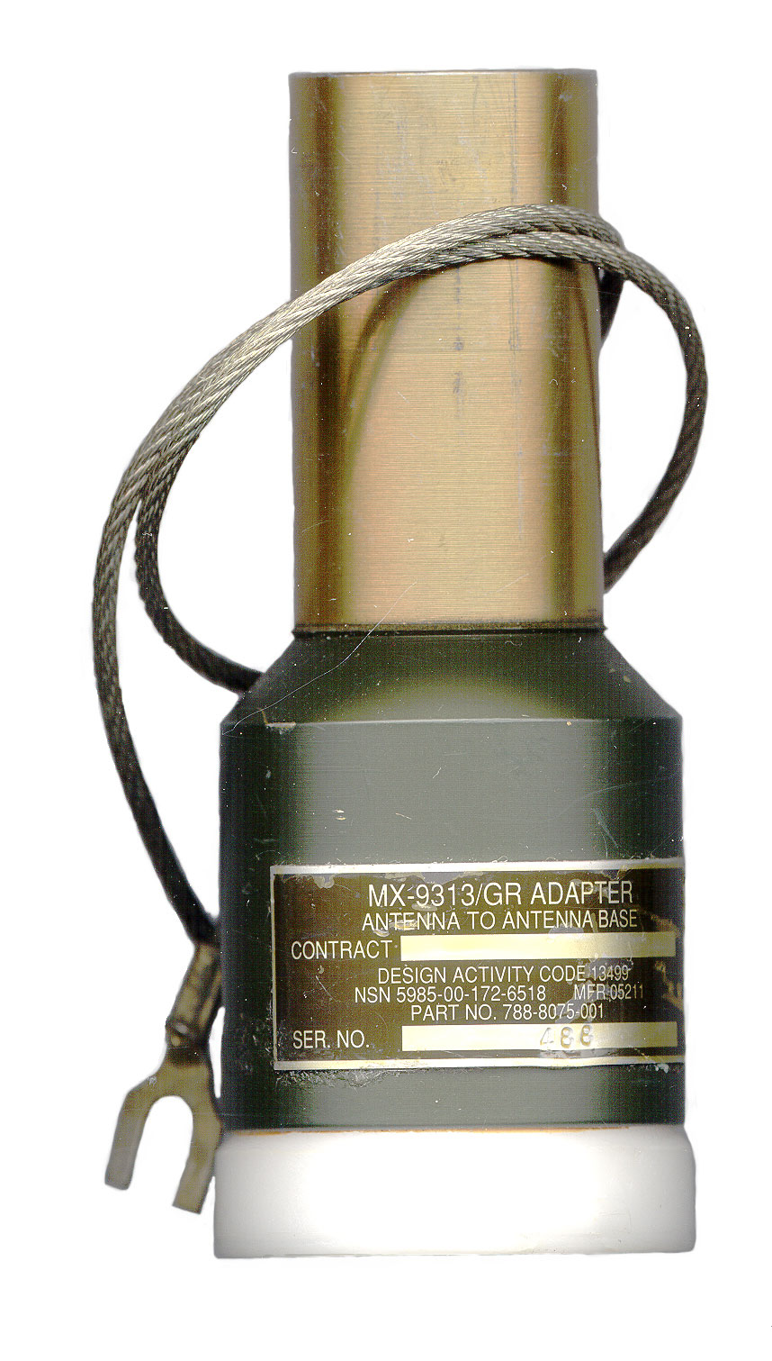
MX-9313 |
|
MX-10618/GRC-193A |
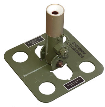
Base adapter allows the AS-2259 to sit on top of MS-116 type mobile or fixed HF antenna bases and has a ground wire to connect to the vehicle ground. Of course the AS-2259 can only be depolyed when the vehicle is parked. Bottom hole is about 0.635" I.D. and has male fingers to fit into a hole in the mating antenna base. Note the threads for the MS-116 start some distance down the hole. This is the AB-652 base that uses MS-116 type mast elements or any base that accepts the MS-116 type antenna elements. |
 |
The MX-10618 is shown here installed on the MP-68 Base that the heart of the RC-292 VHF Low Band antenna. The MP-68 takes the MS-116 Base element both as the lower vertical element and as the first of the 3 ground plane elements. Note the AB-15 Antenna Base is part of the MP-68 and is the actual base that the MX-10618 is designed to be used on. |
NSN 5985-00-106-6130 PRC-47 Base Adapter |
is a base adapter that screws into the antenna connection on a PRC-47. The 3/8-16 threaded stud on the bottom screws into the antenna terminal on top of the PRC-47. Note when the support legs are unfolded on the PRC-47 the front panel is facing the sky. This supports the use of a whip connected directly to the front panel high voltage antenna terminal. It includes an antenna tuning chart attached by chain, for the PRC-47. I tlooks similar to the one on the PRC-47 used with the AS-1320 whip, but the curves are for the AS-2259. |
Home made adapters based on PRC-47 base adapter.The PRC-47 is probably the
most common base and so is often used to make other
types of bases.
|
|
 |
If 4 holes are drilled & tapped up into the bottom of this base adapter it can be mounted on a metal box that has a clearance hole for the 3/8-16 stud. Then a coax connector can be installed on the metal box with a wire between the coax center and the 3/8-16 stud using a wire terminal and nut. These photos are from Mike prcradio at yahoo.com |
 |
There's a 6-32 screw holding the coax center conductor terminal to the center conductor of the PRC-47 base adapter. Not sure if that tapped screw hole is already part of the adapteror if it needs to be added. |
 |
 Edmund supplied photos of this base. |
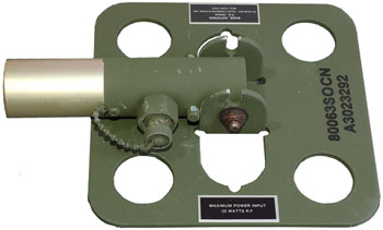
Telex 1994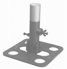 |
is like the Telex 1995 except there is no transformer and it's rated for 1 kW. Thumb screws for ground and hot wires. This is one of the bases with the flat metal plate with a number of holes. The mast part will fold flat aginst the metal base to make carryng in a pack easier. |
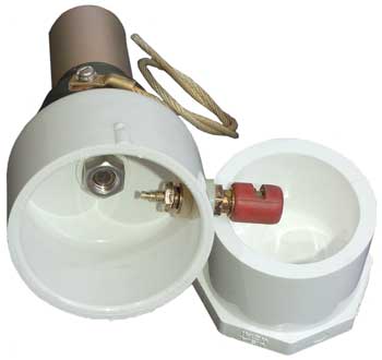
Telex 1995 |
Rated 50 Watts. Has a built in 4:1 transformer allowing easier matching to a PRC-104. The base is a square metal plate with a hinge. For ground mounting. BNC connector. NSN 5820-01-065-4495 Another flat metal base plate unit. |
 Edmund supplied photos of this base. Top Label: BASE, ANTENNA P.N. 1995AA HY-GAIN Div - TELEX COMMUNICATIONS, INC. MFG CODE 37919 Bottom Label: MAXIMUM POWER INPUT 50 WATTS RF |
 |
Telex 1997 |
Adapter has male 3/16-16 thread to screw into the PRC-47 and 1-8 male threads to screw into the 1996 adapter. Using this method two adapters are used to connect the AS-2259 to a PRC-47. |
Telex 1998 |
base adapter mates to the AB652 Antenna Base. Flying ground wire. |
AB-1241/PRC-104 |
Although this looks like a
patio umbrella base, it's only about 8 inches in diameter
(some refer to it as the hubcap base). There's an
R.F. transformer inside so an Ohm meter shows a short
between all the possible terminals. I tried using this base with the AS-2259 and a 50 foot long RG-58 coax to the AM-6874/PRC-104 RF Amp/Ant coupler and it seems to work at 18 MHz, but it's questionable at 4 MHz when the AM-6874 is set for a 50 Ohm antenna (i.e. no tuner). The TM for the PRC-104 says to use a 2 foot cable between the Radio and this base. That's consistent with the idea that the balun is not providing a match to 50 Ohms, but rather is bringing the impedance of the antenna into a range where the PRC-104 antenna coupler can work with. Note impedance has real and imaginary parts and in this case the real part is probably what's mainly being transformed. (At 2 MHz a diploe is much much longer than the wires on the AS-2259 and so it's real impedance is very low, too low to match directly.) |
The Most Secret War, Army Signals Intellegence in Vietnam, James L. Gilbert, ISBN 0-16-051284-0 GPO
TM 11-5985-379-14&P - is available at ETM online.
Contains data and theoretical design considerations for an NVIS antenna. If the ends of the antenna are supported at a higher elevation the antenna will be more efficient, i.e. ground loss will be minimized. The AS-2259 was designed to work with the PRC-47 in Vietnam.
It's mentioned in the manual that when using a vehicle or shelter mount only enough mast sections should be used to get the highest point of the antenna up 16 feet off the ground. Placing the antenna higher will start changing the propagation from NVIS into conventional horizontal polarizatiton and degrade the signal for distances out to 300 miles.
GRA-50 1.5 to 20 Mhz Reel dipole where the reels are at the far ends, not the center. If there are trees or some way to get this antenna up at least 1/10 of a wavelength it will work well.
AT-984/G 150 foot wire
Hy-Gain HA-4000, 18TD, Collins TD-1, 637T-2 - a dipole made with two steel tape measures as the center part. You pull out the tapes, marked in the metric system and you're good to go
Antenna Products - makes a number of NVIS type antennas including the ST-230 sprial
Antenna Systems & Solutions - No images of antennas, seem to be a distributor
Broadband Propagation - South Australia offers HF antennas that look similar to the Bushcom units.
Bushcomm - BBA100 - eHam reviews - 3 wire T2FD type - in U.S. Array Solutions makes the wire antennas here BBA-100 Antenna fitted with Ladder Line Feed Kit (LLF)
KV5R: Getting Started in NVIS Antenna and Propagation Experimentation -
- By Patricia Gibbons - WA6UBE
Tactical-link - NVIS Antennas - W.W.II German recon vehicles By Patricia Gibbons - WA6UBE
Near Vertical Incident Scattering Antenna by Dr. Carl O. Jelinek - palns for a Ham Radio friendly version of the AS-2259
Field Manual 24-18 Appendix M - 2-to 4-MHz range at night and to the 4- to 8-MHz range during the day . . Operators are able to operate from protected, dug-in positions. Thus tactical commanders do not have to control the high ground for HF communications purposes. . . NVIS energy is received from above at very steep angles, which makes direction finding (DF) from nearby (but beyond ground-wave range) locations more difficult.
637K-2B Antenna Tuner made for the AS-2259
The Buddipole N-Vee - Combines the Buddipole with an adjustable dipole
High-frequency radio returns to transformation Army in brigade combat teams - photos of German W.W.II NVIS vehicle ant.
NVIS Propagation Maps - The top link "Inospheric Map - NVIS PROPAGATION North America" has the foF2 data for NVIS. 1 hr updates. But if the Solar X-Ray flux gets too high the "D" layer will absorb the singals.
Near-Real-Time F2-Layer Critical Frequency Map - Australia, but whole world, harder to read than the N. Amer. map above
FM 24-19 Chapter 3 - Antennas
FM 24-18 - Appendix M Near-Vertical Incidence Sky-wave Propagation Concept
Automated HF Communications good for Nap Of the Earth flying -
Mobile NVIS: the New Jersey Army National Guard approach
Near-vertical-incidence skywave (NVIS) propagation: the Soviet approach
Skip the "skip zone": we created it and we can eliminate it
See "The Dave Fiedler collection" for NVIS articles.
Some NVIS: From the Backyard to Professional Installations, Some Notes on NVIS Cloud Burners,
Modeling the T2FD, Notes on the Terminated Wide-Band "Folded Dipole", Horizontal Heights and Sound Bites A Short Note Relevant to NVIS Antennas, by L. B. Cebik, W4RNL
NVIS Com - US Q-Mac outlet
Build Your Own AS-2259 Type NVIS Antenna - step by step with photosNVIS Antennas and EZNEC - Modified AS-2259 - by David McGinnis K7UXO - 80 meter dipole at different heights
Near-Vertical Incidence Sky-Wavve Propagation Concept -
The modified AS-2259 has 4 legs with the following lengths:
57', 56' 4", 28.5'+ <40 meter trap>+18", 28.5'+ <40 meter trap>+18" (works on 40, 60 & 80 meters)
Typical Construction details for the T2FD antenna -
David McGinnis Antenna Modeling various NVIS types including a sprial
a NVIS-ALE Log-Sprial ANtenna for 2.5 - 12+ MHz by L. B. Cebik, W4RNL
Antenna Farm - Two All Band NVIS Antennae by N2CKH/AAR2EY - ladder line fed dipole and long wire
W8JI - NVIS page with some Vietnam era test data -
breck k4che - AS-2259 Antenna Notes - AS-2259 Base Connector - AS-2259 Modeling and Suggested matching - keeping the wire lengths at the stock values
HF Systems - Hourly HAP progagation charts -
HF Link Yahoo Group - Hourly Worldwide NVIS propagation map -
Stealth Telecom - ST-940B - Mag Loop Roof Rack appearance antenna
page[an error occurred while processing this directive] page created 25 Nov 2003.