Bottom
Resistor Mod
Bottom |
Resistor Mod |
This Diplexer is designed to allow two radios operating in the 30 to 76 MHz frequency range to share a common antenna.
Although it appears to be the same size as a PRC-25 or PRC-77 is much smaller at under 10.5 inches wide.51859
SIGNAL TECHNOLOGY CORP (formerly Eaton microwave products div, formerly Addition Labs?)
CALIFORNIA OPN
975 BENECIA AVE
SUNNYVALE, CA 94086
Front View - from eBay
Scan of Front including a ruler -
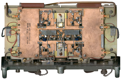
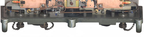
Bottom Inside - showing transistors, taken before adding DC returns to Ports 1 & 2.
Bottom Inside - showing the addition of 2 each 1.8 K Ohm resistors to supply the DC return path for the PRC-126 Squad Radio.
Radio #1 is connected to the left RT1 port.
Radio #2 is connected to the right RT2 port.
The RT1 control is set to null the transmitter on RT2 (which minimizes the RT2 to Ant insertion loss).
The RT2 control is set to null the transmitter RT1 frequency (which minimizes the RT1 to Ant instertion loss).For example if RT1 is operating simplex on 51.0 MHz and RT2 is on 76 MHz then:
RT1 is set for the best null of 76 MHz,
RT2 is set for minimum insertion loss at 51.0 MHz.So from the point of view of RT1 the insertion loss to the antenna is < 3 dB and the isolation of RT2 on 76 MHz is >40 dB.
Now from the point of view of RT2, the insertion loss to the antenna is <3 dB and the isloation of RT1 on 51 MHz is > 40 dB.The two frequencies must be seperated by more than 3 MHz, if not the insertion loss goes up.
Path between Antenna and RT1 - the isolation at 76 is good (-47 dB and IL @ 51 MHz is low (-1.7 dB)
Path between Antenna and RT2 - the isolation at 51 MHz is not so good (-12 dB) and the IL @ 76 is so so (-2.6 dB)
Maybe this used CU-2194 is not what it should be?
The ANT connection is fed to two tunable notch filters. Each filter consists of three cavities ganged in parallel. As the plunger is moved in and out of the cavities a scale is rotated to allow a rough idea of the tuned frequency to appear in a window just about the tuning knob. Both the front panel near each tuning knob and the scale show a frequency range of 30 to 76 MHz.When the tuning controls are adjusted way off from the transmit frequency the power loss from the input to antenna connector is slightly more than 6 dB.
When the tuning controls are adjusted properly the power loss is less than 3 dB.There is a "NULL METER" that can be used to aid setting the filter tuning and for monitoring either radio. The circuitry that drives the meter contains transistors that gets DC power from the RF signals so does not need any batteries.
The RT1 and RT2 ports are DC open. This is not the best for using this box with the PRC-68 series radios that require a DC return for 50 Ohm operation.
The frequency range of the PRC-68 radios in VHF low band is 30 to 88 MHz so the Diplexer is a little short with a 76 MHz high end.
TV chan 5 was 76 to 82 and chan 6 was 82 to 88 MHz.My 68AA Antenna Adapter with used on any of the PRC-68 Family of radios supports the use of the CU-2194.
3624563 Coil and fixed tap input coupling for variably end-loaded coaxial filter, giving linear Q with tuning change, suitable for multicoupler applications, Henry E Burley, William H Martin, Westinghouse, 1971-11-30, - for 30 to 76 MHz, maybe for CU-2194?
TM-07652A-15/1 available from Fair Radio Sales
See NRD-545/Multicouplers for receive only units
VHF-FM Multichannel Equipment Siting Considerations, April 1972 (749186.pdf)
Keywords: FM, VHF, PCC-1, PRC-25, TRC-166, MRC-109, MRC-134, MRC-135
The TRC-166 uses 2 each PRC-25 radios (one for Tx and one for Rx) and the PCC-1 to provide 4 teletype and 4 telephone circuits plus an order wire. Either separated whips are used for Tx & Rx or the CU-1857 dilexer/duplexer is used with the AS-2236 LPA antenna. The paper looks at separations of 25, 50 and 150 feet.
The MRC-134/135 uses the RT-525 as Tx and R-441 as Rx with the VCC-1 to provide telephone, telegraph and order wire. The antenna options are the same as above.
Phone
Channels
TTY
Channels
Order Wire
Channels
VCC-1
4
4
1
VCC-2
8
8
1
Back to Brooke's Products for Sale,
Military Information, home page
page maybe created 2009