Electrical Testers
© Brooke Clarke 2024 Description
Human Safety
Equipment Safety
Solenoid Electrical Testers
Wiggy
Ideal Vol-con
Klein ET250
Voltage Tester Patents
Voltmeters
Ampere Meters
Continuity Testers
Test Lights
Photos
Related
References
Links
Background
I have a bunch of testers aimed at electronics and have used some of them when working on household AC circuits. But recently, when troubleshooting dead outlets, became aware of specialty testers aimed at working on the AC power wiring so started this web page.
Description
Human Safety
A large portion of electronic circuits run on battery power, like cell phones, and so there's no danger of a fatal electrical shock. Even power line powered electronic equipment typically runs on low voltage DC so the only portion that's a shock hazard is the AC power supply.
U.S. household AC is at either 120 or 240 VAC and these potentially fatal voltages show up around the world. The main difference between electronic testers and electrical testers is that electrical testers are focused on human safety. Small manufacturing facilities and commercial buildings might have 277, 480 and/or 600 VAC wiring. Higher voltages are found in the AC power distribution (Wiki, Telephone Poles) and transmission (Wiki) systems and these have their own specialized test equipment for voltages over 1,000.
Fluke has a web page dedicated to Safety.
When working on old radios and television sets where the DC voltages were typically up to 500, a rule of thumb was to only use one hand, keeping the other hand in your pocket. This idea is to prevent a current going through your heart, which might prove fatal. A related idea is to stand on an insulating surface to prevent a path from your working hand, through your heart to a ground under your feet. These same ideas apply to electrical testing and the testers have features to support doing this. For example many electrical testers have a long skinny form factor and provision for the test device to hold one or both probes so that you could clamp the ground lead and using one hand probe the circuit being tested.
Equipment Safety
I used to have a cheap Radio Shack multi-meter with an analog meter movement. Similar to the Harbor Freight SKU: 59434. I had been using it in the Ohms mode to check continuity and some days later picked it up and connected it to a live circuit (assuming that it was in voltage mode which was the case most of the time). In short order smoke came billowing out of the meter. This is typical of multimeters with a manual function selection dial. If the dial is in the wrong position you will not get a correct reading and there's a good chance you will destroy the meter. If you were working on AC mains wiring this mistake may cause the meter to melt in a fraction of a second severely burning your hand.
One characteristic of electrical testers is that they often do not have a manual function select dial or they automatically change modes. There are in fact testers that will test for continuity and voltage whichever makes sense. This is exactly the type of testing that destroyed my old multi-meter. I learned about this when a string of three dead outlets appeared after a power outage. It would be desirable to check continuity, but doing that on a live AC circuit using electronic testers would be asking for trouble. Hence the need to an electrical tester.
Solenoid Electrical Testers (SET) (Wiki)
These go back to the early 1900s and were a low cost way to not only tell if a circuit was live but also give a rough indication as to the voltage. They are based on iron vane voltmeters which work for both AC and DC.
The wiki page points out that these can be used to test Ground Fault Interrupters (Wiki) by connecting the Wiggy between hot and ground (instead of hot and neutral). This works since the Wiggy draws current unlike modern high impedance DMMs.
They are a very early example of Haptic feedback (Wiki) since the solenoid generates different vibrations for AC and DC and the strength of those depend on the applied voltage.
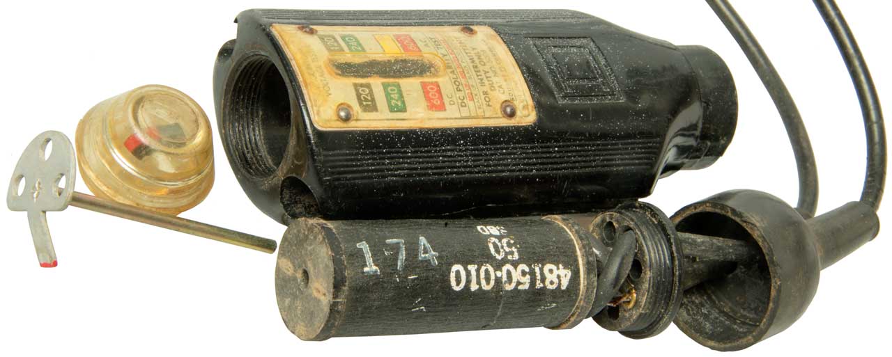
Wiggy
At some point in time these were made by Square D (Wiki).
Made on patents: 1538906, 2075860, 2479186, 2524841.
Photos
Fig 1
Fig 2 I must have lost the spring that goes between the armature and coil.
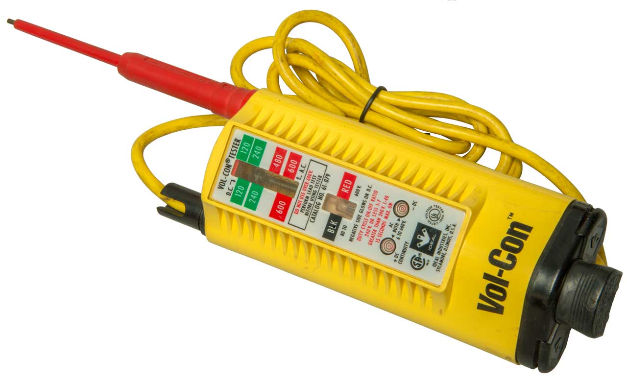
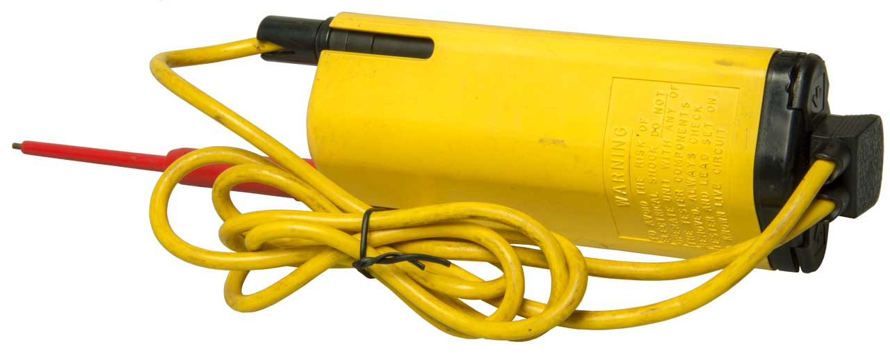
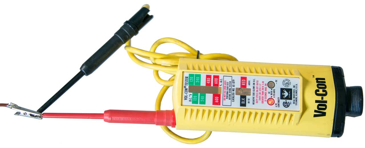
Ideal Vol-con
As received the voltage detection function worked on a 120 VAC outlet, but the continuity function did not, probably due to dead batteries.
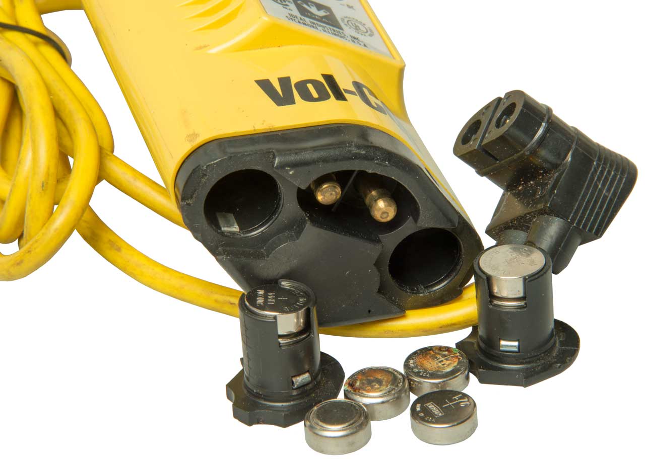
Prior to taking Fig 3 I installed new batteries and turned the dead batteries so that the corroded side was up. After assembling the tester the continuity function still does not work.
Opened up and removed batteries. Cleaned all contacts, batteries, battery holder & main body and assembled. Note it takes some force against a table top to properly seat the two battery holders and the test lead plug.
Shorting the two brass pins lights red +DC LED as does shorting test leads. Now fully functional.
Notice that there are no controls. You just connect the probes to a voltage or to a circuit where continuity is to be determined.
Fig 1
Fig 2
Fig 3 new & old batteries.
Fig 4 Continuity
Versions
Ideal made many versions of their Vol-con (combined Voltage and continuity) tester. The 61-076 (Ideal) may be the most popular version and is still being offered as of Feb 2024. It uses proprietary test leads and there was a recall on a prior version of the test leads.
Model
Features
Link
61-065
100 - 600 VAC/VDC
YouTube
61-076
5 - 600 VAC/VDC & Continuity
61-079
Same as 61-076 except with slim line leads (61-081) (4ea:LR44batt)
Test Lead Recall
61-092
24 - 600 VAC/VDC, Lights simulate Solenoid scale & vibrator, NCVT
YouTube
61-096
Split-Jaw, Volts, Amps, Ohms, Continuity - all auto selected (no dial)
YouTube
Safety
It turns out there's a safety consideration because of the solenoid overheating and/or exploding. See the Fluke white paper.
Most manufacturers are discontinuing the real solenoid type testers for this safety reason. Some of the newer testers have lights arranged like the solenoid scale and include a shaker motor to simulate the vibration associated with solenoid operation. A key advantage of the Solenoid Electrical Tester is that you can feel what's happening and do not need to see the scale since the vibration is proportional to the voltage level. The vibration also acts as a warning. Note there is an operational note on all of the Solenoid Electrical Testers saying something like to make a connection for no more than 10 seconds and then allow a 2 minute cool off period prior to using again.
I have had a number of Fluke test leads open because all the wires broke in the same plane.
See Hints & Tips\Fluke Test Leads
Got the Fluke TL175 test leads because they are covered by two patents and also in the hope that safety rated test leads will have working strain relief.
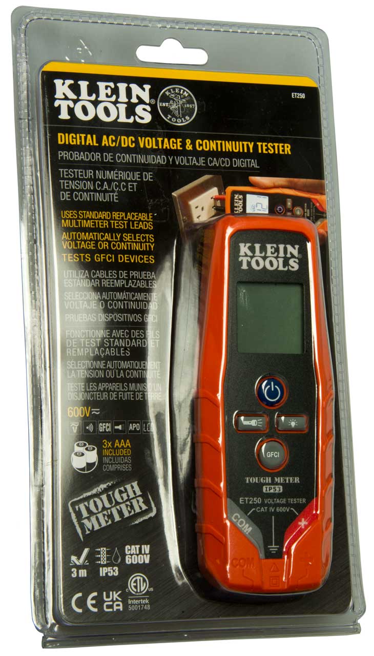
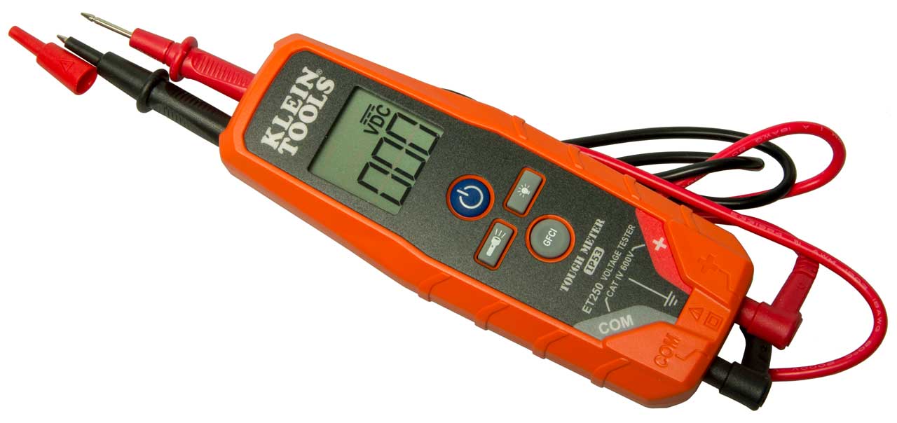
Klein ET250
Fig 1
Fig 2
The Klein ET60 was a sister version of the ET250. The ET60 has a series of LEDs arranged to mimic the look of the mechanical scale on a solenoid electrical tester. It does not require an battery (the ET250 uses 3 each AAA batteries) and presents a low impedance to the source of voltage to mimic a SET. The probe holders are spaced to match US outlets.
The ET250 uses a high impedance digital voltmeter and has a button that supplies a low impedance for testing GFCIs.
The ET250 has no Haptic feedback.
Voltage Tester Patents
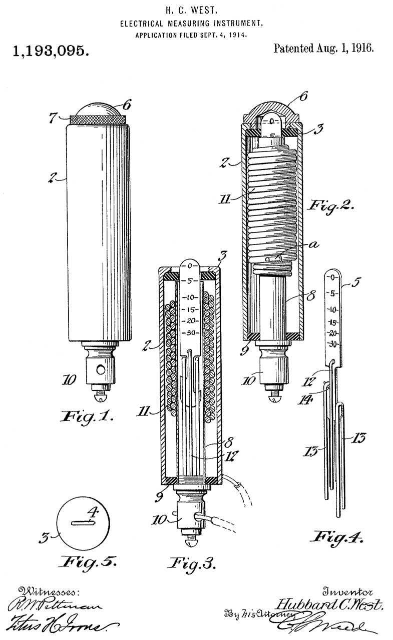
1193095 Electrical Measuring Instrument, Hubbard C. West, 1916-08-01 - solenoid moves for DC voltages up to 30V.
This has the look and feel of a pocket Ballon Tire Gauge.
What could go wrong when the metal scale extends out of the body?
Iron Vane voltmeters that work for both AC and DC were well known in 1916.
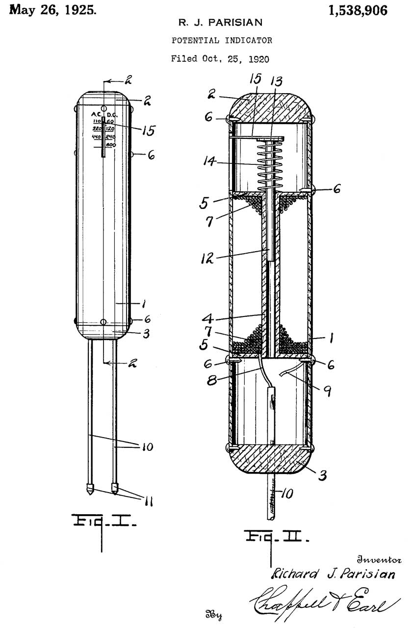
1538906 Potential indicator, Richard J Parisian, Wigginton Co, 1925-05-26, - This is the original Wiggy Solenoid Electrical Tester.
The magnetic field pulls the indicator down so it is always inside the housing, unlike 1193095 above.
Note the AC scale (110, 220, 440) on the left and the DC scale (60, 120, 240, 600) on the right.
2075860 Voltage tester, Hugh F Mehaffle, Wigginton Co,1937-04-06, - two parallel springs, test leads anchored
2479186 Voltage tester, Leon L Simkins, Wigginton Co, App: 1946-04-20, W.W.II, Pub: 1949-08-16, - case/probe
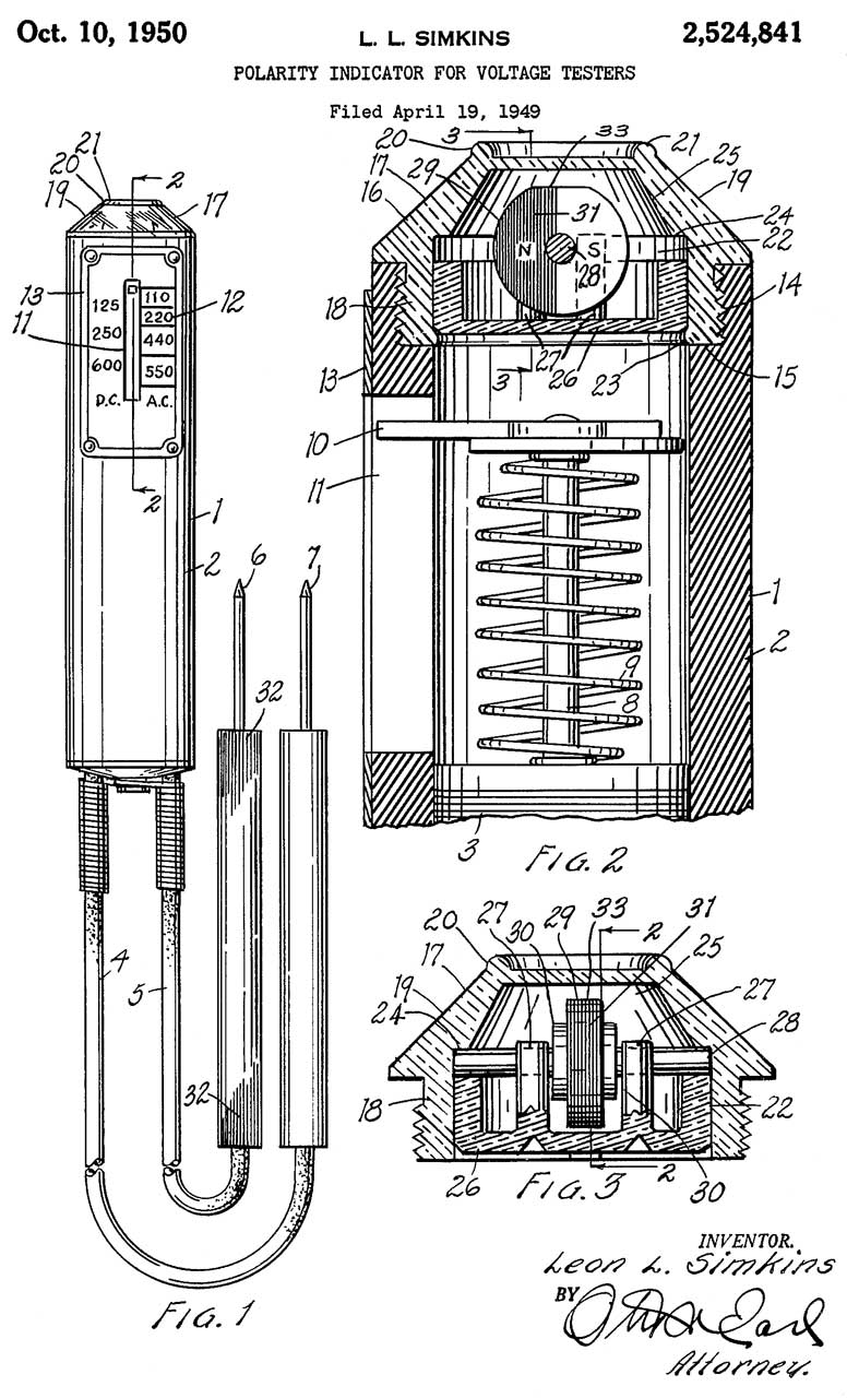
2524841 Polarity indicator for voltage tester, L. Simkins Leon, Wigginton Co, 1950-10-10, -
The magnetic field off the end of the coil will be either a North or South pole when the input voltage is DC. By placing a disk shaped magnet just above the pole under a clear dome the polarity of the DC input can easily be identified. When the input is AC the disk will move back and forth, I doubt it will turn like a motor amarture, but in any case the disk will add move vibration for an AC input voltage.
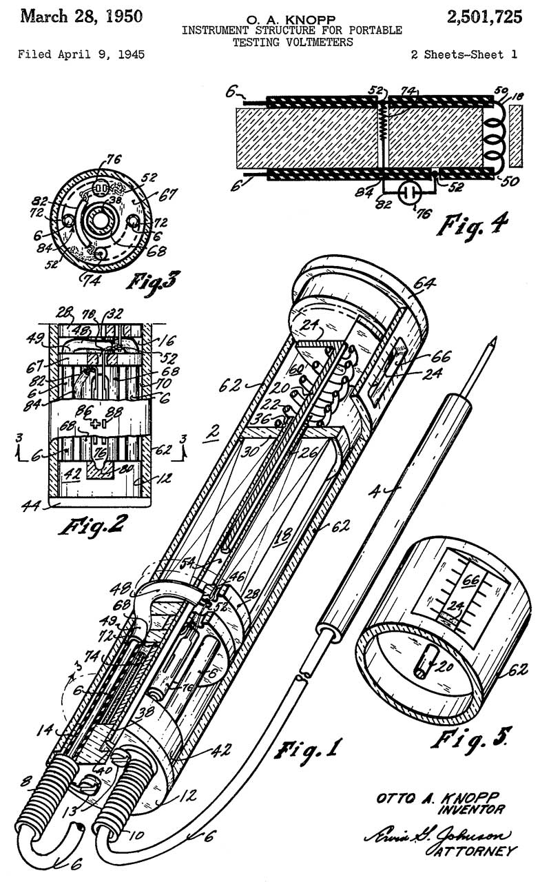
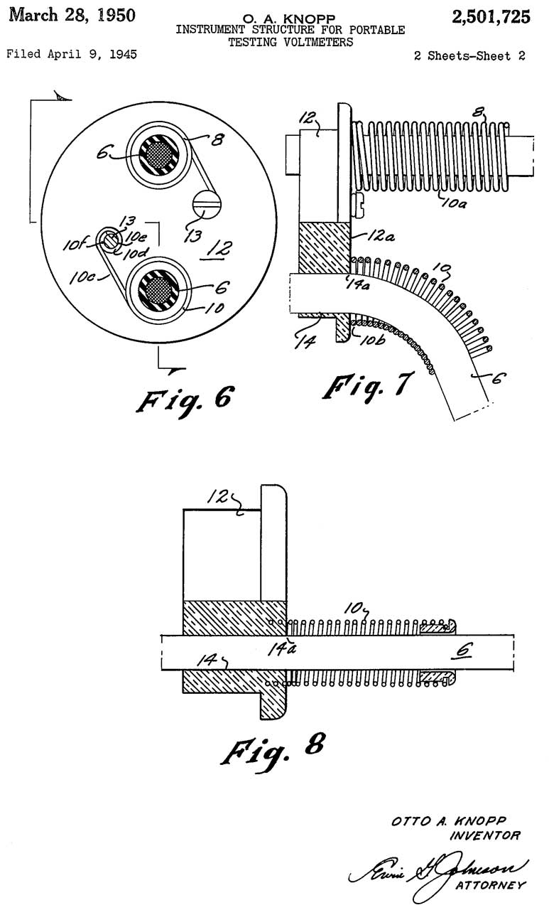
2501725 Instrument structure for portable testing voltmeters, Otto A Knopp, 1950-03-28, -
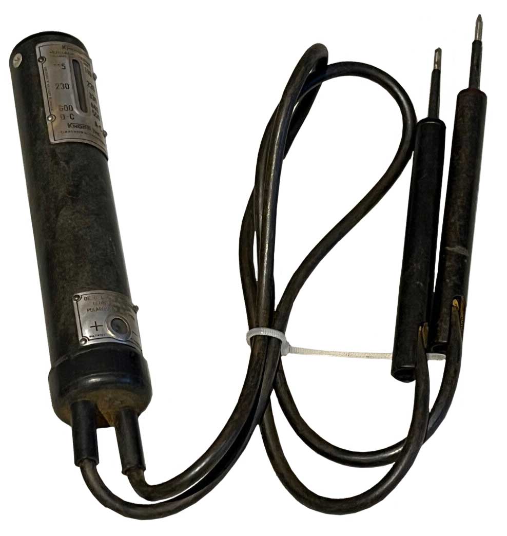
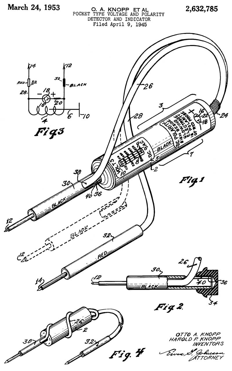
2632785 Pocket type voltage and polarity detector and indicator, Harold P Knopp, Louise B Knopp, 1953-03-24, - hand held solenoid electrical tester with Neon bulb for DC polarity (much lower in cost than the magnet wheel.
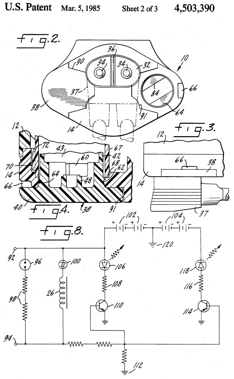
4503390 Switchless voltage, continuity and polarity indicator, Peter M. Wells, Jr., Ideal Industries, 1985-03-05, -
Ideal Vol-Con 61-076 & 61-079 (Ideal Vol-Con brochure.pdf) -
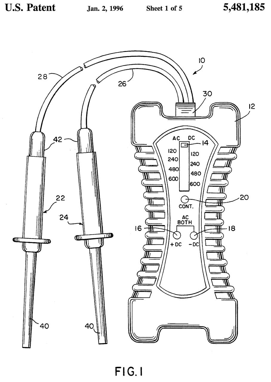
5481185 Solenoid, type voltage, polarity and continuity tester, Peter B. Lane, William M. Hinz, GB Electrical, 1996-01-02, -
GB used to be called Gardner Bender (Wiki, Official Web Page)
Voltmeters (Wiki)
Early Iron vane Voltmeters (Wiki) were very inacurate and so only used in labratory settings, not the field. For example the test for a No. 6 Dry Cell battery, called Flash Amps, was done using an Ampere meter. This was the case until about 1935 when the Weston Model 1 which perfected the d'Arsonval movement (Wiki) was intoduced.
1057276 Electrical measuring instrument, Lewis T Robinson, Otto Holz, Matie D Holz, GE, 1913-03-25, - Fig 2. Iron Vane (19) shaped so meter displays voltage.
Ampere Meters (Wiki: Ammeter)
One of the measurements might be Inrush Current. This can be done with a special button or by using the Min/Max peak hold function.
When used for Locked Rotor Amps (LRA) on an air conditioner compressor the LRA value may be in the 100 to 200 Amp range.
Also see Generators\AC Starter Kit.
Classical d'Arsonval movement (Wiki: Galvometer)
Shunts (Wiki)
These are just resistors, often rated for power, that allow measuring currents higher than the meter movement by itself. A common size is 50 mV for 100 Amps. The current is determined by using a mV meter to read the voltage across the shunt. They come in many mV and current ratings. In some cases a wire that's already in a system may be characterized for resistance and used as a shunt.
Current Transformers (Wiki) & Split-core CT Clamp Meters
AC only. A resistor must be placed on the output of the CT, otherwise the voltage would try to go to infinity. The air gap in a split-core CT causes errors for low currents. Not a problem when there are many loads downstream of the CT, but may be a problem for a small number loads or where you are measuring small currents.
Clamp Meters (Wiki)
To get more sensitivity wrap the wire into a coil. If there are 5 wires going through the clamp the meter will read 5X the actual current.
Iron Vane
These work with both AC and DC.
1924039 Electrical measuring instrument, Hockley Harold William, Crompton Parkinson Ltd, 1933-08-22, - Columbia Electric "Tong-Test" - iron vane in finger that's part of interchangeable heads for different current ranges. (0-20, 0-30, 0-40; 0-50, 0-100; 0-75, 0-1000; 0-75, 0-500; 0-75, 0-1000).
Hall Effect (Wiki)
Works for DC.
Rogowski coils (Wiki, Fluke)
Very flexible, can be opened, so easy to install on wire and can be wrapped to increase sensitivity.
Fluke 376 FC True RMS AC/DC Clamp Meter with IFlex Review, 6:20 -
Fluke 378 FC with FieldSense™ and Fluke Connect, iFlex included!, 6:14 -
Magnetometer (Wiki)
The HP 428 Clip-on milliammeter uses a magnetometer sensor.
Open Fork
Two parallel fixed jaws instead of a moving clamp. Much more convenient in tight places.
Fluke T5 & T6
Open Fork measurement of current. A big improvement over the clamp meter.
Fluke T5-600, T5-1000 open fork for amps, but probes for voltage. 1/2" Fork gap too small for Extech 480172 (1" thick but wall size not specified).
T6-600, T6-1000: Both T54 & T6 have grounding button on back of meter (capacitance to user's bare finger) - will not work with PPE gloves.
Fluke T5 Pro & T6 Pro
These include "FieldSense" non contact measurement of voltage, current and frequency! See patent 20180136263 below.
T6-1000 Pro: non contact current and voltage "FieldSense" measurement, no grounding button, but instead alligator clamp for ground lead. Visual continuity turns screen back light to green.
The Pro version includes a black ground clamp which allows the non contact voltage measurement to work better than just body capacity.
non removable test leads. Same price as prior T6. The Fluke Store at Amazon shows 4 probes and ground clamp, but the carry holster does not have spaces for them. It should be redesigned to hold them.
Adam Wysor goes over the Fluke T6-1000 PRO True-RMS Electrical Tester with FieldSense Technology, 2:25 -
Five ways FieldSense technology can help you work safer -
9 Things You’ll Love About the Fluke T6 Electrical Tester -
6043640 Multimeter with current sensor, William J. Lauby, Charles A. Bublitz, Charles R. Jensen, Brian S. Aikins, Steven W. Fisher, Fluke Corp, 2000-03-28, -
20110156696 Multimeter, Steve Cheek, Christopher W. Lagerberg, Hui Wang, Fluke, 2011-06-30, - TPAK Magnetic hanging strap
20180136263 Non-contact voltage measurement system using multiple capacitors, Ronald Steuer, Peter Radda, Fluke, 2019-05-07, - FieldSene non contact voltage measurement.Continuity Testers (Wiki)
These started appearing around the same time as flashlights.
Gardner Bender - GCT-3304 Heavy-Duty Continuity Tester
Patents
Search my flashlights web page and do a CTRL-F for "tester".
There are also special versions for testing (Telephone, LAN, Audio, USB) cables.
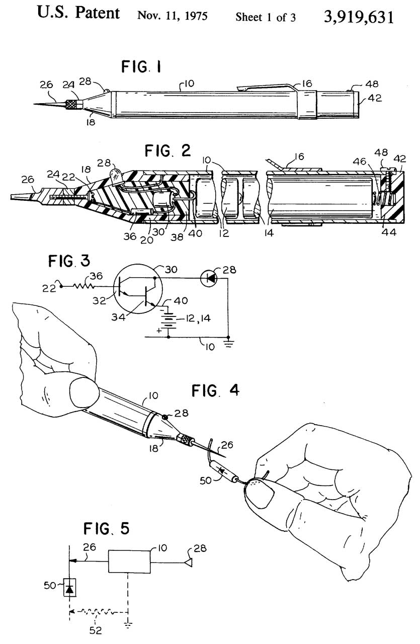
3919631 Leadless probe, Richard D Brown, 1975-11-11, - for continuity, not AC voltage detection
Test Lights (Wiki)
If the voltage of a circuit is known then a lamp with test leads can be applied to a circuit. If the lamp lights the circuit is hot.
Examples of known voltages are vehicles where the battery voltage is known in advance or AC wiring.
In the case of AC wiring there is a big safety issue with making contact with the voltage source, hence the development of non contact voltage testers.
Contact
1906644 Electrical test stick, Harvey P Sleeper, 1933-05-02, - "outside illumination from falling upon the transparent gas containing tube, hereafter termed a neon tube" - used as a test light, neither for illumination nor for flashing because of an AC voltage.
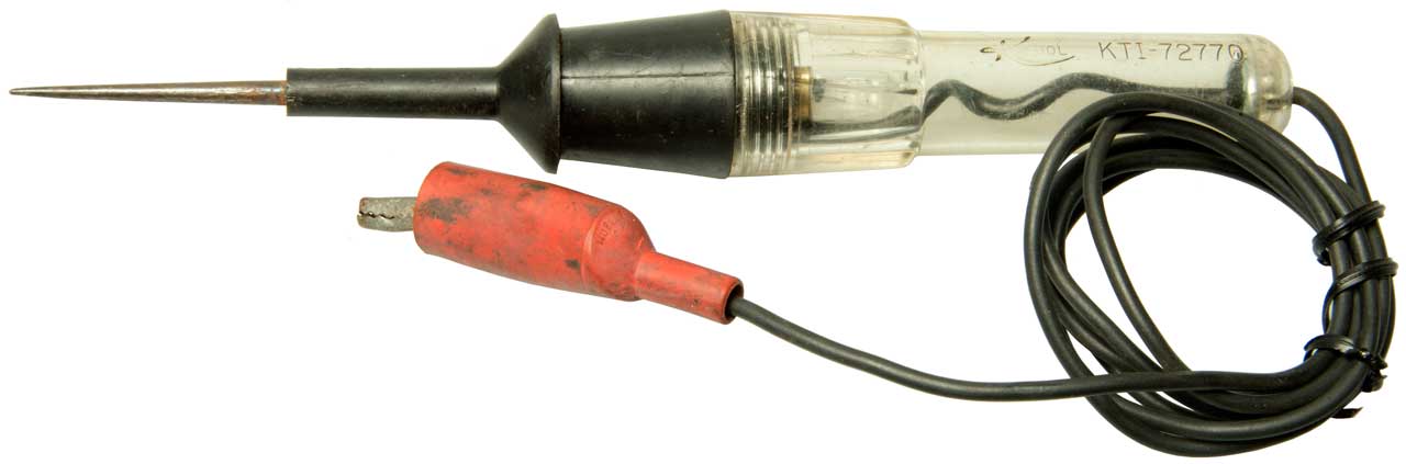
K-Tool International KTI-72770
This is just a 12V bayonet base lamp inside a clear handle awl with a test lead with alligator clip (boot Mueller No. 62).
Non Contact
Non Contact Voltage Detectors (Wiki)
These have gone through an evolution based on safety considerations. These work by doing nothing if there is no voltage present and give an indication if voltage is present. There's a big problem if the battery is dead, there is no indication even when voltage is present, hence a risk of death. The current models include an "on" light to show the battery is good, but there may be a defect inside, like after being dropped, so for safety you should always try the NCVD on a known live circuit to confirm proper operation. I expect future versions will have a built-in AC voltage test source that will automatically activate whenever the unit is turned on, i.e. a Built In Test function.
Ideal
Fig 1
Fig 2
Versions
Model
Range
VAC
Flashlight
Power On
LED
Battery
61-627
50-600
No
Yes
2x AAA 61-637
24-600
Yes
Yes
2x AAA 61-647
50-1000
No
Yes
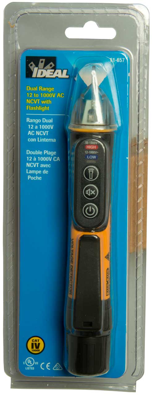
2x AAA 61-657
12 - 1000
50 - 1000
Yes
Yes
2x AAA
Patents
2109189 Electrical testing and detecting apparatus, Bly Merwyn, 1938-02-22, - battery powered, sense rod antenna, 3 tube amplifier, headphones or meter. - cited by 15 patents
2698921 Testing instrument, Donald A Wharton, 1955-01-04, - 1D8GT tube (1D8GT.pdf) (amp and detector sections)
3009099 Testing instrument for electric alternating voltages, Muller Otto, Schiffmann Alois GmbH, 1961-11-14, - 5 vacuum tube hum amplifier
4724382 Testing instrument for detecting alternating voltages in mains and alternating electromagnetic fields in the vicinity of voltage-carrying conductors, Hubertus Schauerte, 1988-02-09, - switching transistor drives Darlington pair transistor to light LED.
5103165 Insulated, hand-held non-contacting voltage detection probe, James M. Sirattz, Static Control Components (Santronics Inc), App: 1990-11-19, Pub: 1992-04-07, - MC1458 Dual Op Amp
5363045 Hand-held non-contacting electric field detection tool, George G. Martin, Thomas J. Martin, 1994-11-08, - based on 555 IC.
5877618 Hand held non-contact voltage tester, Thomas M. Luebke, David L. Wiesemann, Power Products (Applied Power), 1999-03-02, - five stages of 4069 Op Amps drives LED & buzzer.

Photos
Fig 1
Fig 2
Related
DMM - Digital Multimeters
Electro Optical Gadgets, Aircraft Cockpit UV Instrument Lights
GE Portable Induction Test Meter Type 1B5Y - 1880s; Sangamo Analog Electric Meter - 1880s
Infrared
Microwave Test Equipment
Optical Spectrum Analyzers
Smart Meters
Telephone Test Equipment
Test Equipment
Ultraviolet
References
Ref 1. David Herres: All About Wiggy, 2014 DEc 22 - goes over many of the features of the first generation Wiggy.
Ref 2. Proving Dead - Mains Electricity, 17:18 -
Ref 3.Was this the first LED test light?, 8:55 - Steinel brand
Links
PRC68, Alphanumeric Index of Web pages, Contact, Products for Sale
Page Created 2024 Feb 16