

|
|
|
|
|
|
From: Business Digest
July-Sep 1917 pg 668Toys - Selling ofAn authorized interview with Alfred C. Gilbert, president of the A. C. Gilbert Co., New Haven Conn. Mr. Gilbert is amateur wrestling champion of his weight in this country, and incidentally holds the degree of doctor of medicines. Last year he sold around $1,400,000 worth of toys and by-products into the marketing of which he had put $140,000 in advertising. He started in business less than seven years ago with a capital of $1200, saved from money earned while working his way thru the Yale Medical School. He is now president of the Toy Manufacturers of the United States.Mr. Gilbert has concentrated on toys that bring into play considerable thought, study and practical imagination on the part of the boy purchasers. The Gilbert business began with Mysto Magic and then put out Erector and Briktor model toy building outfits, electrical and wireless devices. The Gilbert appeal has been keyed on"the fun of doing actual things the way real men are doing them." Mr. Gilbert in his college vacations had acquired a wide reputation as a sleight-of-hand magician on vaudeville circuits. He used to give classes in the mystical are, but found that his pupils lacked patience. So he used to invent simple devices and mechanical tricks which they could perform easily. When he first started his business, manufacturing the trick outfit Mysto Magic, he did the traveling among the department,hardware and toy stores, and was kept busy giving parlor magic exhibitions between Thanksgiving and Christmas. After a year or two in spite of a modest success, he foresaw an approaching point of saturation as far as Mysto Magic was concerned. So he bought out in 1913 Erector, a construction toy with many parts on which he holds certain patents. The best idea that can be given of the possibilities of the toy is that a boy, with the aid of a toy motor, made a working model of one of the Panama Canal locks. With the launching of this toy he started advertising, and with it came immediate success. From the first appearance of Erector in 1913 the company has made it a practice to give lists of prizes for the most ingenious models constructed with the toys. After the preliminary sorting a committee of real engineers judges the best models. In 1915 Gilbert started a bi-monthly boys' paper called Erector Tips. Some capital is made of boy hero-worship in an occasional article by Gilbert himself on such subjects as "How I became a world's champion athlete,", etc. In the 1915 contest some 60,000 models were submitted for prizes, so, as there were only 300 prizes, Gilbert knew there would be a great deal of disappointment. So he planned his Institute of Erector engineering, the courses of which confers three degrees, Erector Engineer, Erector Expert Engineer and Erector Master Engineer. To win these the boy must submit photographs of Erector or Briktor models. The Gilbert Co. makes a special arrangement with dealers by which they are given all the models and advertising material free of charge n addition to a certain amount of display, material, a model for window use, etc. In return the dealers just put the sign in the windows at least five weeks before Christmas: "Boys I will give these models away free to the boys who make the best models. All models must be brought to my store and displayed in my window before Christmas." Mr. Gilbert told the writer that he had been an omnivorous but careful reader of business literature - books, and magazines, clipping the important paragraphs for reference. |
|
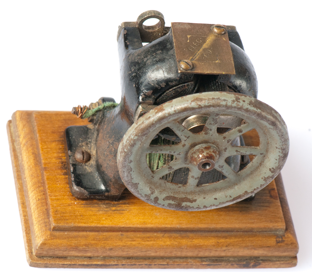
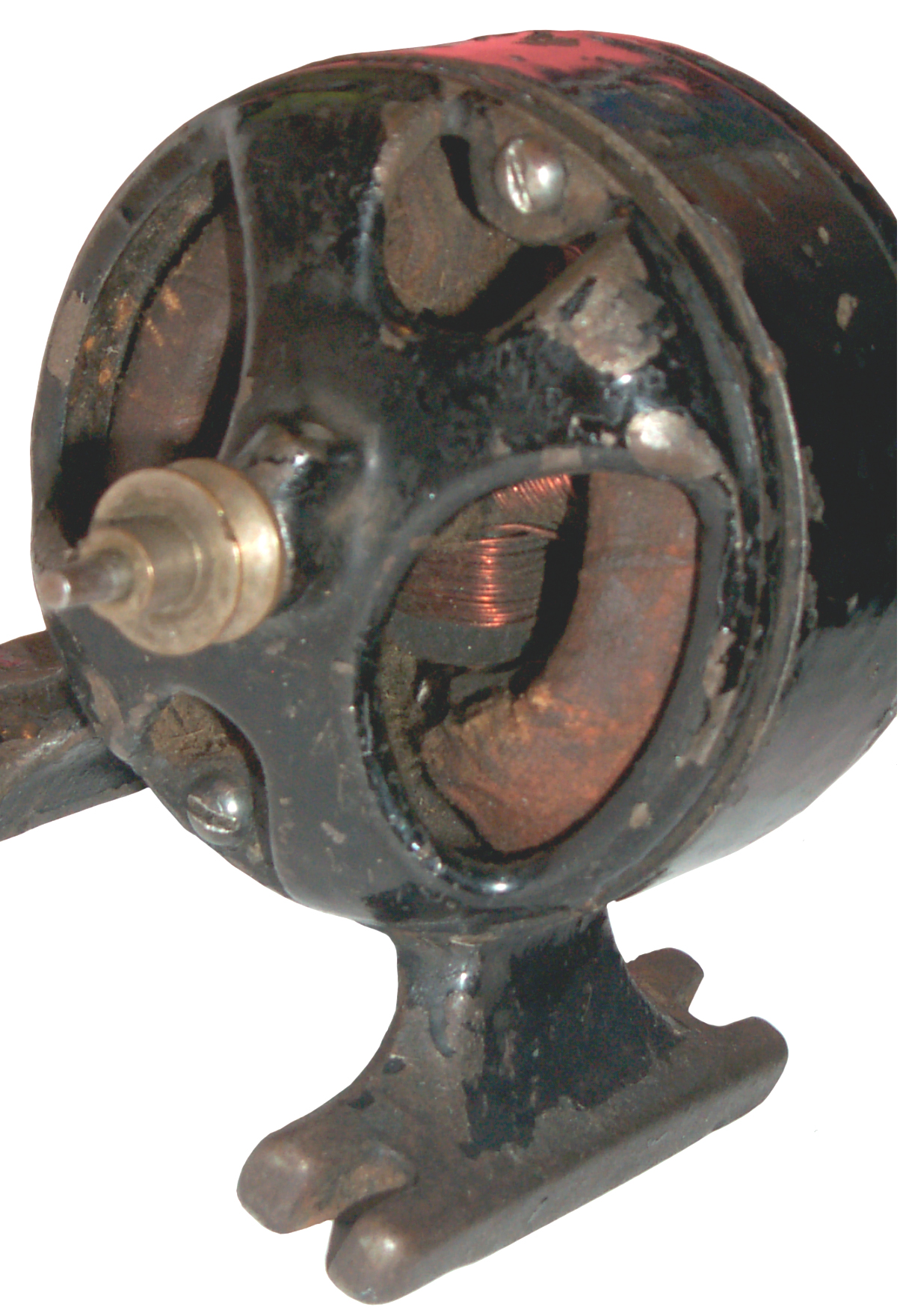
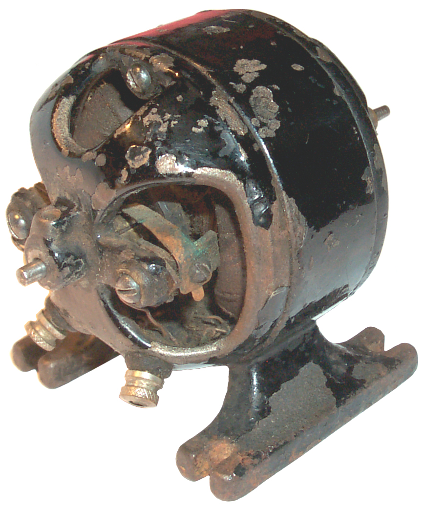
Motor Assembly
Instructions Wanted.
|

Repair
Working
YouTube: Brooke95482:Erector Set First Gilbert DC Motor, 0:24 - Christmas 2007
Reversing Switch Base P59
 |
 |
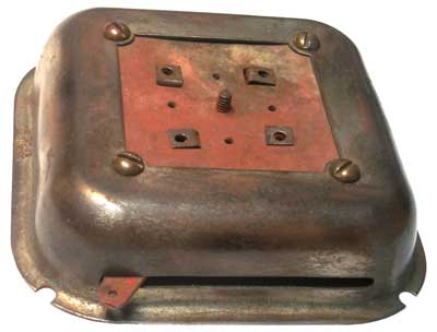
| Gilbert
Erector Set Switch Base Top |
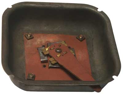
Gilbert
Erector Set Switch Base Bottom |
Brushes
Batteries
2022 - Adding this paragraph because there's an important battery parameter that is not commonly specified and that's the internal resistance. I first came across this when working with the
Tamiya Grasshopper RC car. After buying new batteries the original owner said it was not as strong as he remembered. See YouTube:
Duratrax Sprint 2 ESC Problem when Starting - The problem turned out to be the internal resistance of the battery pack. Jan 2022 - I'm testing the internal resistance of tool batteries like Riobi and B&D. It turns out that the makers of modern tools have different batteries that have the same voltage and Amp hour capacity, but differ in internal resistance. But they don't tell talk about that. They just give them some marketing difference, like "HD".
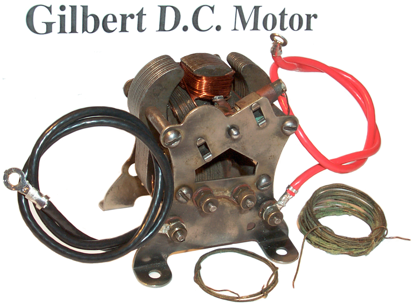
The old No. 6 Dry Cell batteries had very low internal resistance and so would power small motors, like the Gilbert, with high torque but using more common batteries like the pre W.W.II flashlight type batteries would not provide the same high torque performance.
Mysto Mfg Patents YouTube: The Dark Story of Gilbert Toys: How Erector Sets Built America - Then Collapsed, 53:24 - Mysto was the first company founded by Alfred C. Gilbert. Included Polar Cub Electric Fans (Vibrator).
1010794 Trick device, John A Petrie, MYSTO Manufacturing Co, 1911-12-05, - "...a “disappearing” act in connection with a lighted cigarette."
1066809 oy Construction Blocks, Alfred C. Gilbert (Mysto Mfg Co), Jul 8 1913, 446/112 ; 446/113; 446/124 - the basic beam with flanges
RE14250 Toy Construction Blocks, Alfred C. Gilbert(A. C. Gilbert Co), Jan 16 1917, 52/634 - the Reissued patent has a change from Mysto Manufacturing company to A.C. Gilbert Co and a change in the patent classes. Top class 446 is Amusement Devices: Toys and 52 is Static Structures (i.e. Buildings).GB191501259 (eSpaceNet) Toy Building Construction, MYSTO Manufacturing Co, 1915-12-30, - same as US 1066809.
Gilbert Patents
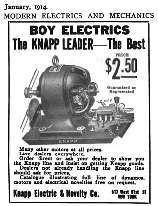
| Popular Mechanics Ad Mysto Mfg Co. 1913  |


 |
 |
 |
First attempt at
reconstructing a brush 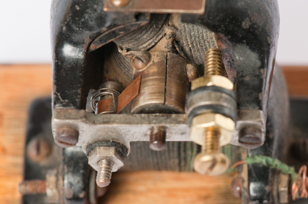 |
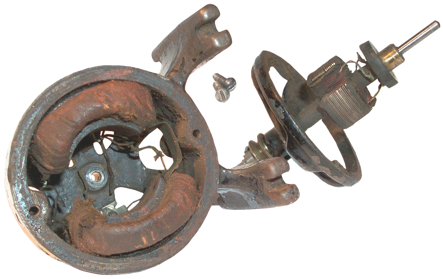
At this point it was easy to measure the resistance between the armature windings by holding the DMM probe against the brass screw. Bad news almost all the coils show open. 2 out of 3 bad in the armature and the field coil is OK. As shown above both field wires are connected to the right terminal, so measuring between the terminals shows open. But when the wire is moved to the left terminal the coil works. |
Armature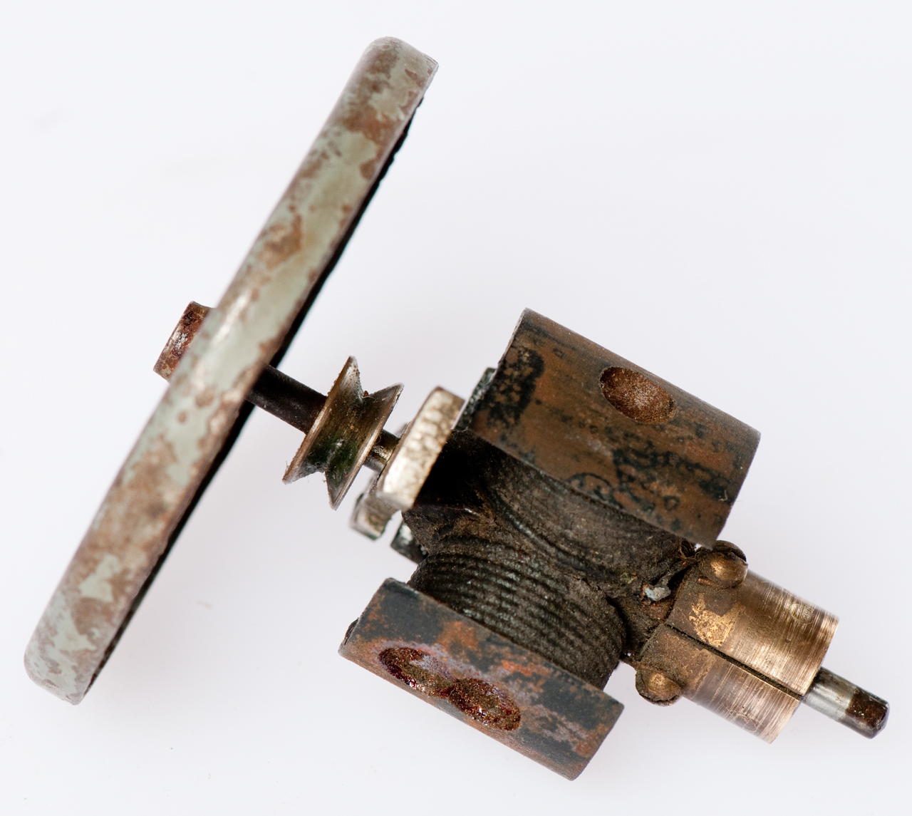 |
 |
 |
 |
| Pulley
End |
Shaft
End with thumb nuts as the connection terminal |
 Armature
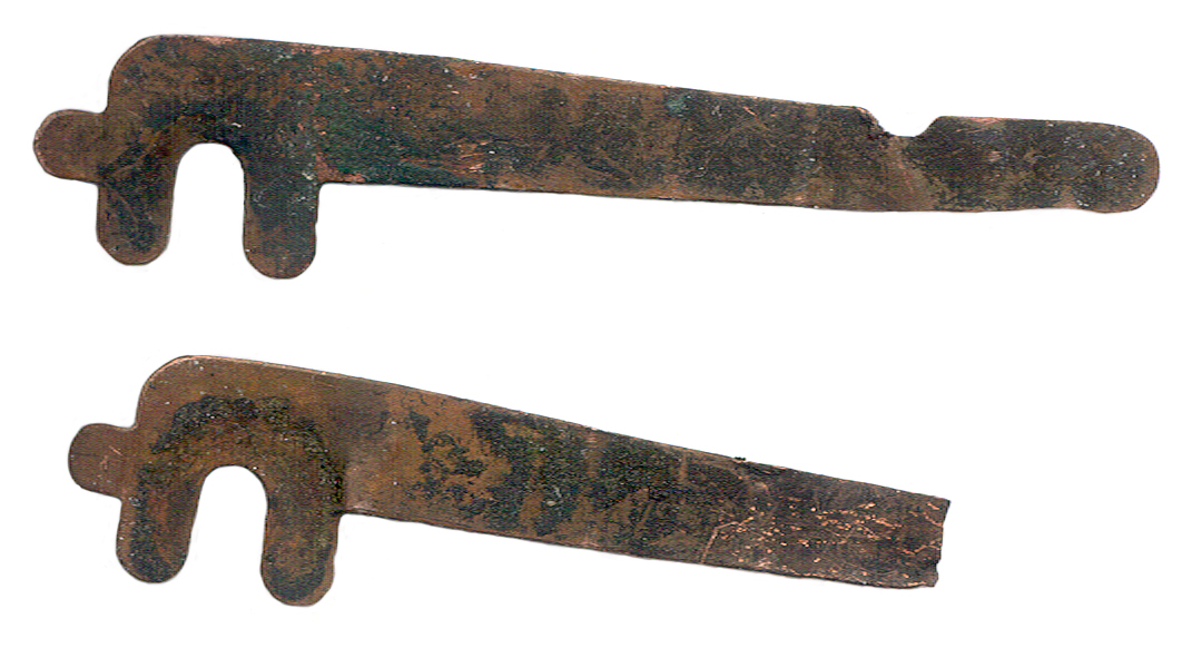 The brushes are made of sheet metal that
should have some spring action, but have lost the
springiness. One of them has a missing contact end.
The brushes are made of sheet metal that
should have some spring action, but have lost the
springiness. One of them has a missing contact end.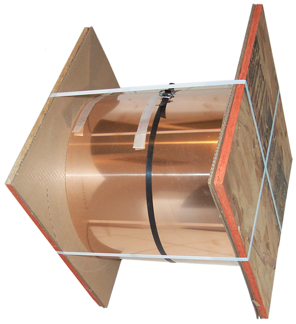
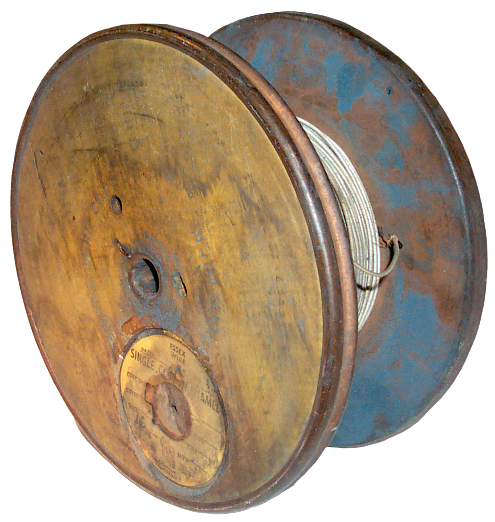 |
Found some # 16 Cotton Covered wire the
spool is 8 1/4" OD and the space inside the
flanges is 2 3/4". After getting it home and
cleaning the grime from the spool found two patent
numbers: 1365406 Spool, Eber J. Hubbard, Jan 11, 1921, 242/118.8 - A sheet metal & wood spool suitable for fine wire. 1609473 Spool, Eber J. Hubbard, Dec 7, 1926, 242/118.8 - Textile Mill spool uses sheet metal over wood. The wood Spool is also marked Essex Wire Corp. Detroit Mich. The round yellow paper is printed Essex Wire, Anaheim, California and has "Single Cotton Enamel" # 16 and that's the wire on it. The enamel is a dark color. The single cotton thread is made up of about 16 strands twisted together and the diameter of that bundle is about 0.013". The blue stuff on the inside face is that same stuff that was on the outside and really looks gray, maybe like this spool was near a grinder and is a combination of stone and metal dust. It wiped off so now hopefully it can be handled without needing to wash you hands. |
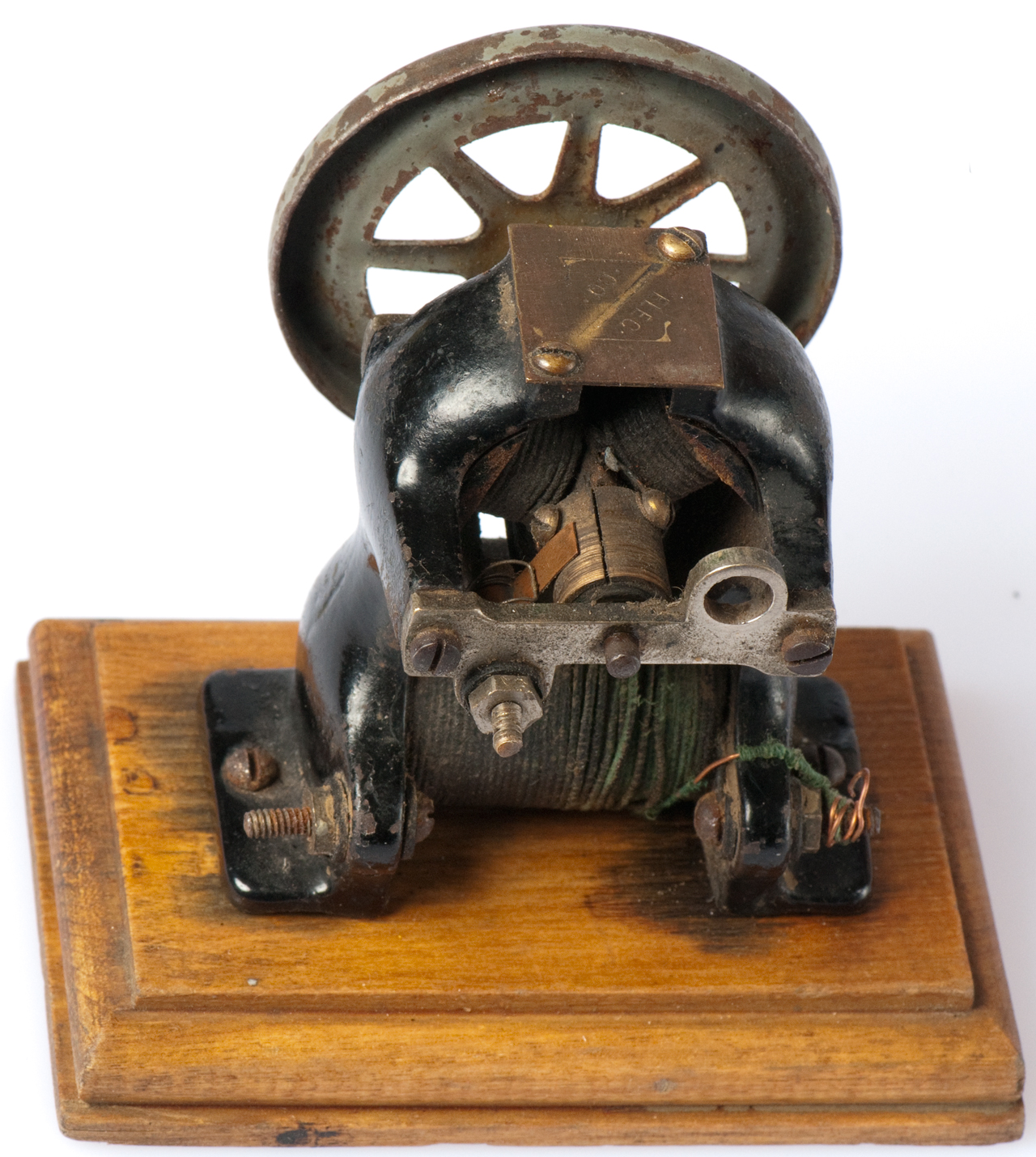
The bipolar motor (Wiki) only has two poles to it's stationary magnetic field. All the motors on this page are "bipolar" since all of them only have two magnetic poles.
10480 Electro-magnetic Engine, Charles Page (Wiki, Hall of Fame), Jan 31, 1854, 310/21 -
oldest patent in class 310/21 -
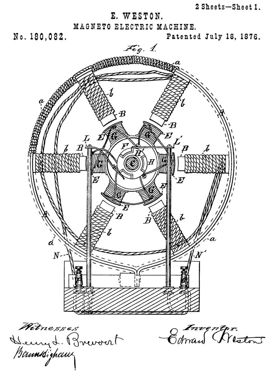
180082 Magneto Electric Machine, E. Weston, 1876-07-18, 310/46 -
also see:
Weston Model 594 Photronic Cell, Weston 603, 614, 615, 617, 650, 703, 715, 756, 819 & others
Weston Model 1 Volts Milliampers D.C. Meter; Leeds & Northrup 2420-A Galvanometer
RE8141 Dynamo electric Machine, E. Weston, 1878-03-26, 310/46 -
Re Issue of 180082 above.
297273 Field Magnet for Dynamo Electric Machines, J.W. Lawson, Apr 22, 1884, 310/216.037 310/216.003-
Using a bundle of soft iron wires to form Field Magnet (Wiki) for bipolar motor. This was done after the use of soft iron rods and prior to Electrical Steel (Wiki).
Also see the Synchronizing Coil in a newer Self Winding Clock Co. It is laminated and uses Electrical Steel instead of the solid iron rod cores used in the prior dual coil synchronizing coil.
Around 1892 Steinmetz was publishing papers on Electrical Steel for loss reduction.
The combination of laminations (Wiki) and Electrical steel both increased the efficiency of electric motors.
298955 Dynamo-electric machine, T.A. Edison, 1884-05-20, 310/225; 310/220; 310/255 -
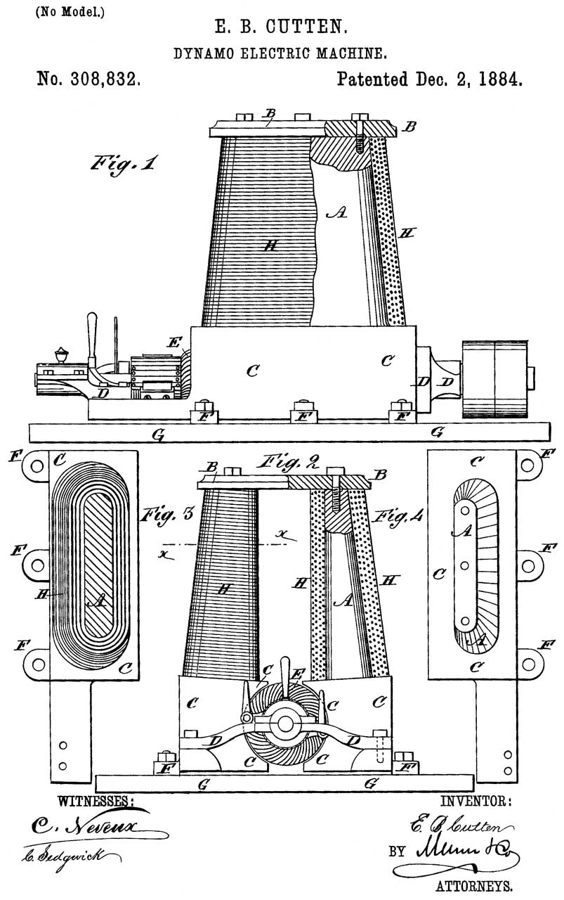
308832 Dynamo Electric Machine, E.B. Cutten, Electrical and Mechanical Developing Co, Dec 2, 1884, 310/216.037 310/425 - Classical look of a bipolar motor. Gilded Age (Wiki).
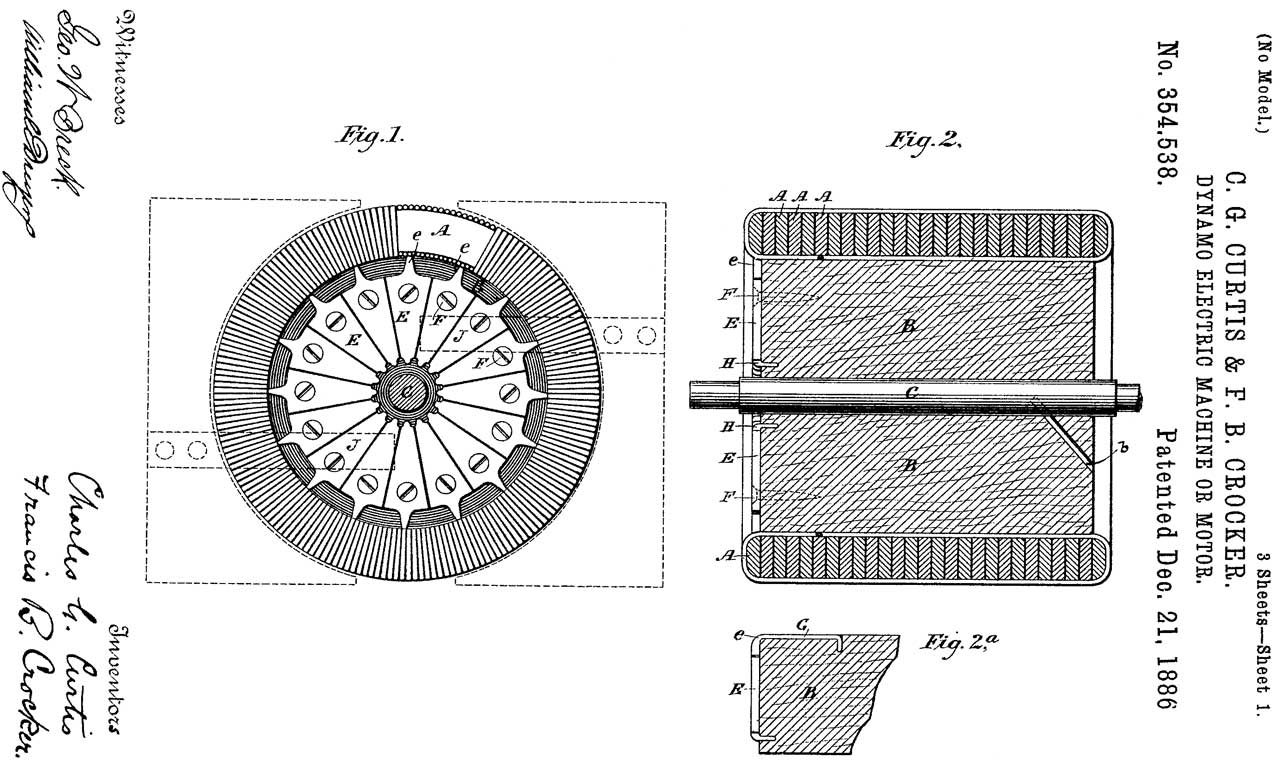
354538 Dynamo electric Machine or Motor, C.G. Curtis & F.B. Crocker, 1886-12-21, 310/267; 310/219 -
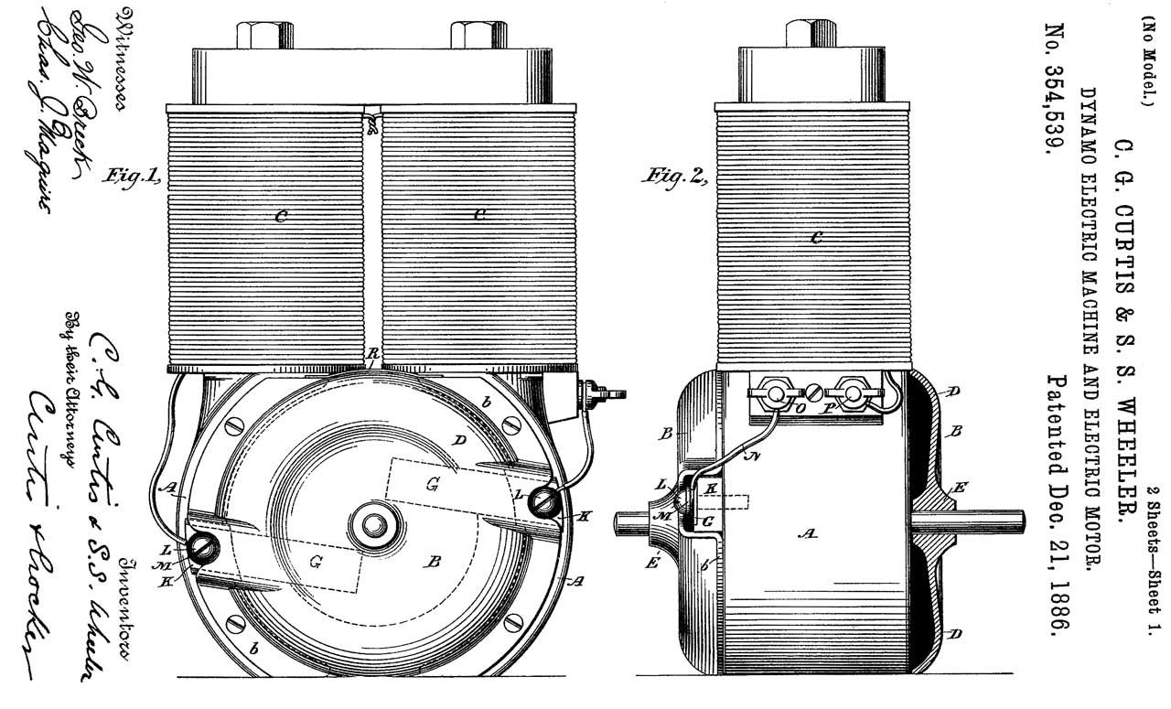
354539 Dynamo electric Machine and Electric Motor, C.G. Curtis & S.S. Wheeler, 1886-12-21, 310/40R -
354588 Dynamo Electric Machine and Electric Motor, S.S. Wheeler & C.G. Curtis, C. & C. Electric Motor Co, Dec 21, 1866, 310/267 -
eBay item 283836332032
Maybe I can get some photos of the motor on eBay? Let me know.
359205 Armature and Process of and Apparatus for Forming the same, C.G. Curtis, S.S. Wheeler & F.B. Crocker, C. & C. Electric Motor Co, Mar 8, 1887, 310/267 29/605 174/126.1 336/192 29/598 140/92.2 336/229 242/573 242/437.4 -
eBay item 283836332032
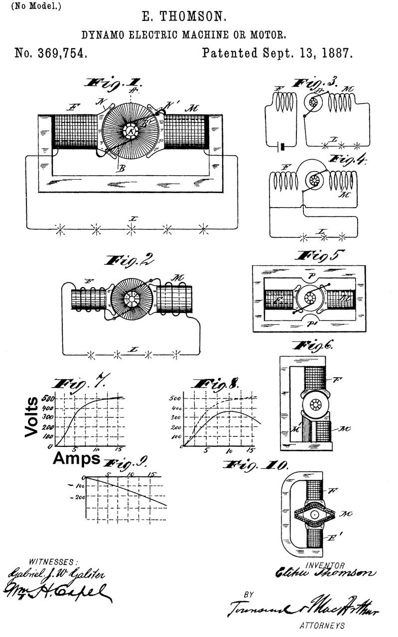
369754 Dynamo-electric machine or motor, E. Thompson, 1887-09-13, 310/188 -
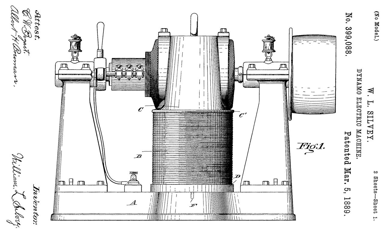
399088 Dynamo electric machine, W.L. Silvey, March 5, 1889, 310/216.037 310/216.079 310/425 - 403487 Dynamo electric machine, Frank A. Perret, May 14, 1889, 310/216.037; 310/216.127 -
Perrett 1889 Bipolar DC Electric Motor (eBay 254582756889) weighs 105 lbs, 1/2 HP, Patented May 14, 1889:Maybe I can get some photos of the motor on eBay? Let me know.
451872 Electric Motor, F.M. La Boiteux, Henry Varwig, May 5, 1891, 310/66 310/233 310/216.121 310/216.037- field magnet made from iron tubing flattened to form pole pieces.
The armature is clearly shown as laminated, but that's not mentioned in the patent.
451884 Electric Motor or Dynamo Electric Machine, S.S. Wheeler, Crocker-Wheeler Electric Motor Co, 1891-05-05, 310/267 -
Kt = 1352.4 / Kv, Ke= Kt / 1.3524 , Ke = 1000 / Kv , Kv = 1000 / Ke
So what good is all this? It means that given a source of known rotational speed (an electric drill, or drill press if you have one), you can compute Ke for a given motor (clamp the motor shaft in the drill's jaws, measure the resulting open-circuit voltage, then do the math).
Ke, along with the above information will then give you Kt (so you can compute your motor's theoretical torque at any given current), and Kv (so you can compute your motor's maximum speed at any given voltage). If you can measure stall torque (YouTube: Stall Torque Demonstration on Small DC PM Motor), you can then compute motor efficiency (measured torque expressed as a percentage of the theoretical torque).
The above web page is aimed at permanent magnet DC motors that can act as generators. This motor when spun by hand only generates about 50 mV with the field series connected with are armature. Permanent magnets can be used to replace the field coil and iron core. Another option is to use separate connections for the field and armature. That's why there are four terminals on the Gilbert DC motor.