Battery Testers
© Brooke Clarke 2007 - 2022
Background
State Of Charge
Radio Shack 22-080 Household
Battery Tester
ZTS Mini-MBT
ZTS MBT-1
TS-183 Mil Dry Battery Tester
PSM-13 belt carry Mil Radio
Battery Tester
TS-4403 LiSO4 Mil Radio
Battery Tester
TS-23 BA-1574/U Mercury
battery Tester
Drop Test
Capacity Testing
Coulomb Counting
Resistor
Filament Flashlight
Bulb
Constant Current
Constant Power
Electronic Load
Watt's Up
Maha 777Plus
Maha MH-C9000
Triton2
iMAX B6 LCD Screen
Digital Lipo NiMh Battery Balance Charger
1.5v~12v
Battery Capacity Meter discharge Tester 3.7v 18650 lithium
lead-acid
BF-1L Battery Fixture (Single
Cell)
Foxwell BT-705 Battery Load
Tester (see Brooke's Vehicles web page)
Internal Resistance
Examples
EVB ESR/Low Ohms Meter
HP 4328A Milliohm Meter
ESR-Cap meter
SM8124 Battery Impedance Meter
SM8124A
Battery Impedance Meter
Dynamic
Resistance
Shelf Life
Analyzers
Cadex C7200
Flash Amps
Links
Background
There are a number of reasons why
you might want to test the capacity of a battery. For
household type batteries it's good to know if it's the battery
that has died or the device holding the battery. When
working with rechargeable batteries it's good to know the state of
charge, i.e. what's the capacity.
I've found a number of cases lately where the Radio Shack battery
tester shows in the middle of the green, yet the battery is not
powering the device.
State of Charge
These testers estimate the remaining
life of a battery. For Carbon Zinc and to a lesser extent
Alkaline this can be done by measuring the battery voltage while a
light load is applied. If the proper load is chosen for a
given battery capacity the loaded battery voltage works well as an
indicator of remaining life. The idea is to determine the
state of charge using as little of the batteries capacity as
possible.
HP 66311A Mobil Communications DC
Source
This test instrument was specifically designed to measure the
power consumed by battery operated devices, like cell phones,
and to measure the associated battery and battery charger.
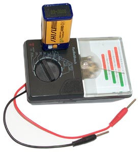
Radio Shack 22-080 Hand Held
Battery Tester
Aug 2007 -
Added
test jack table to
TS-183 web page so that the Radio Shack load resistors could be
compared to the TS-183 load resistors. The Radio Shack
tester showed a 9 volt battery as good yet the battery would not
work in the Stamps.com postal scale. The TS-183B showed the
resistor as bad after abut 5 to 10 seconds. There's a 100%
difference in the load resistors for this voltage. Need to
check the others.
In addition to the test leads this battery tester also has metal
contacts for a 9 volt battery on the front panel, the negative
contact and be used on the bottom of AA, C, D battery and the red
lead to make testing easier. On the right side is a slot for
button cells and part of the front panel can be depressed to make
contact to them. For most common batteries I have used this
tester, but now am no longer as confident in it's abilities.
| Range |
RS
Load R
|
Yellow
V
|
FS
V
|
TS-183
Load R
|
1.5v 1 ma
button cell
|
1k7
|
1.13
|
2
|
|
3v 1m
Lithium cell
|
3k4
|
2.27
|
4
|
|
AAA &
N 50 ma
|
30
|
1
|
1.6
|
|
AA
& C & D 150 ma
|
10
|
1
|
1.6
|
6
|
Photo 6v
|
600
|
4
|
6
|
|
9 volt
|
900
|
6
|
9
|
544
|
| 12v |
1k2
|
8.3
|
12
|
|
| 15v |
1k5
|
10
|
15
|
|
| 22.5v |
2k3
|
15.5
|
22.5
|
|
ZTS
Mini-MBT
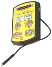
Since the above Radio Shack tester does not
work very well I've been on the lookout for an improved
tester. ZTS makes a number of handheld battery testers and
the Mini-MBT (Multiple Battery Tester) is what got. They
have a utility and a design patent.
6823274
Apparatus and method for testing remaining capacity of a battery,
Nov 23, 2004, ZTS,
702/63 ; 320/125; 320/136; 702/64;
702/65; 702/79
uses voltage at end of resistor load
pulse.
D515444
Battery Tester - packaging for the 6823274.
When a battery is connected it's immediately under load and after
a few seconds the loaded voltage is read. The capacity is
based on the loaded voltage at the end of the test
time. The patent has data on the load resistance for 8
different battery types as well as capacity information in 20%
steps for 3 & 6 Volt versions of the CR123 photo battery and
for the 1.5 volt alkaline terminal.
The four battery types that the MBT will test are:
Cell Type
|
Details
|
Ni-MH
|
1.2
volt
|
Alkaline
|
AA,
AAA, C, D, N
|
Lithium
|
CR123,
CR2, CRV3
|
Alkaline
|
9V
|
I checked the same battery that the Radio Shack tester showed in
the green and this tester either shows it as bad or on the second
try it failed to start the test, meaning it's dead.
Also checked some CR123 cells that have been here for years.
They test at different levels. I haven't made any controlled
discharge tests to see how accurate this tester is, but at a first
look I like it.

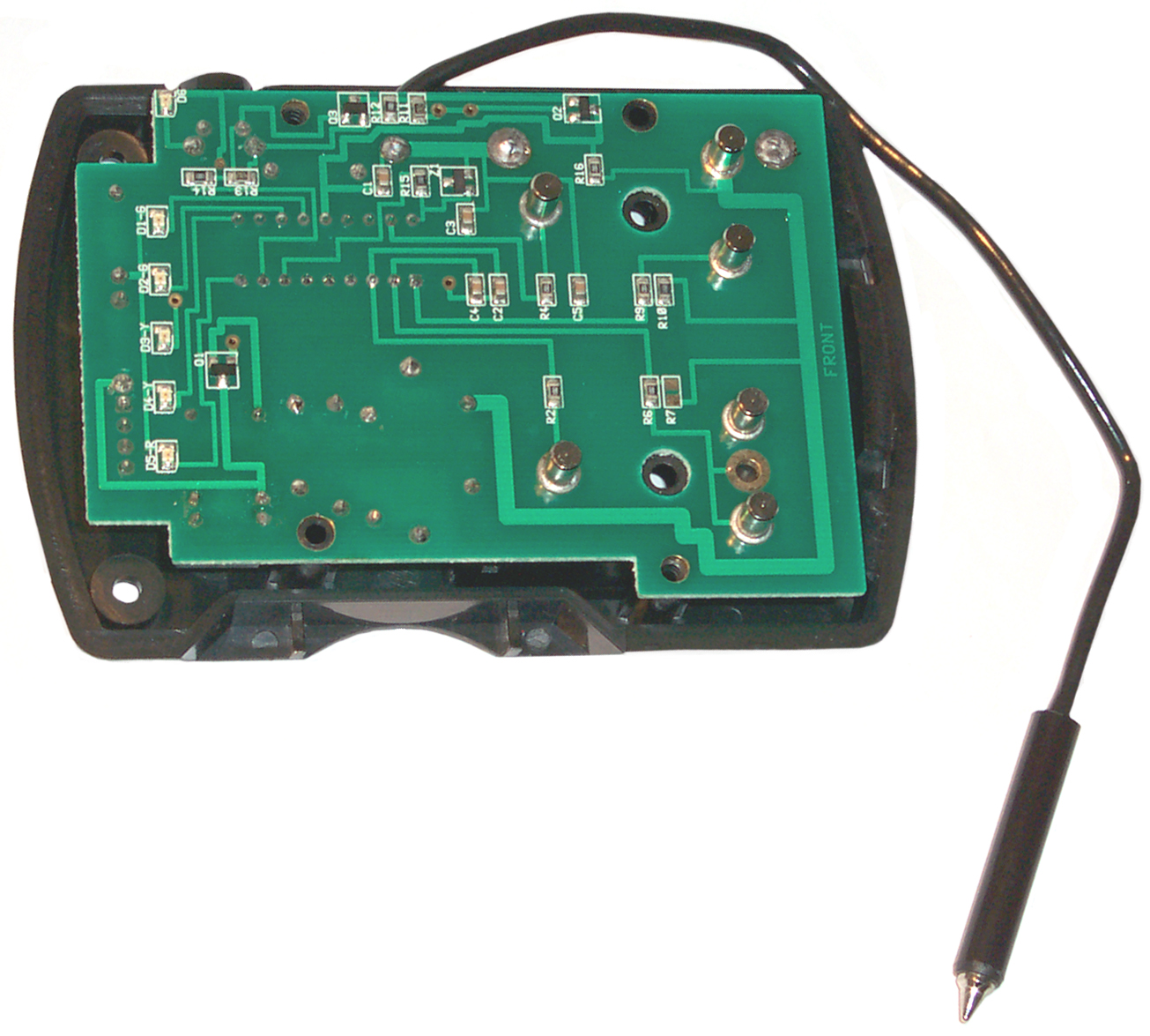
The Mini tester uses a
socketed 18 pin micro controller without a seperate MUX IC and
without an external crystal. The circuit board is soldered
to the positive and negative battery terminals and so can not
easily be removed. There's a 4 post 0.1" header for testing
the unit, but it's between the PCB and back cover so is not
accessible after the front cover is removed.
Instead of using a switch like on the Radio Shack tester, this one
uses 4 different positive battery terminals and a common negative
test lead. There's a groove around the tester to hold the
lead and a pocket for the short probe body on the left side not
shown in the photo. The On button is on the right side.
There are two lower priced ($30) models this one (Mini-MBT) and
the MINI-MBT9R. The difference is that on this one the lower
left terminal is for the CR123 Li-MnO2 primary battery and on the
other one it's for a Rechargeable 9 volt battery. I
specifically wanted to try the CR123 battery test since I use
these in some of my products (
5BA,
90BA Battery Adapters).
The
TS-183 works the same way.
You pick the test jack to match the battery instead of using
switches. The load is permanently associated with the
jacks. For example on the TS-183 jacks 1, 2, 3, & 4 are
for single cell batteries and 1.40 V is the 80%
indicator. Jack 3 is for a "D" Zinc Carbon battery and
uses a 6 Ohm load. The ZTS tester is using a 9.1 Ohm for
alkaline cells with a 80% voltage of 1.41 V. ZTS could
eliminate the whole relay circuit and thus lower the cost of the
tester since one of the connections to the cell under test is by
the probe. That's to say whoever is testing the battery has
to hold the probe on the cell If there was a socket
holding the cell then the relay has some merit, but in this case
it's not likely someone will "forget" and keep holding the probe
on the cell for an extra hour or more.
There are some aspects that could be improved.
- Using a post for the battery positive terminal seems to be
upside down. Either use a socket for the positive
terminal or make the post for a negative terminal. It's
not as bad as balancing a pin on the point of another pin, but
not that far different.
- The display is at the top so when you are holding a battery
upside-down on one of the posts with one hand and holding the
probe with your other hand the display is somewhere behind
your hands. Better to place the display at the
bottom. If you turn the unit upside down then the
display reads backwards and the labels are all upside down,
and you need to be left handed, but it still a better way to
use the stock tester.
- The On button seems to get activated whenever the unit is
handled. Maybe put it on the top narrow face where you
don't normally hold the tester.
- The word Pulse" does not seem to have anything to do with
how it works. The load resistor is always connected to
the test terminal so the battery sees the load as soon as the
circuit is compleated. When powered up the tester scans
all the terminals and when it finds on with a voltage starts a
timer. At the end of the time (always 3 seconds?) it
reads the loaded battery voltage. So there's no pulse
involved. Then, after making the measurement the relay
opens the load resistor to keep from draining the
battery. Maybe this is what they mean by pulse?
These are nit picks. This is be far the best battery tester
I have.
They make more expensive testers
that can test a longer list of batteries.
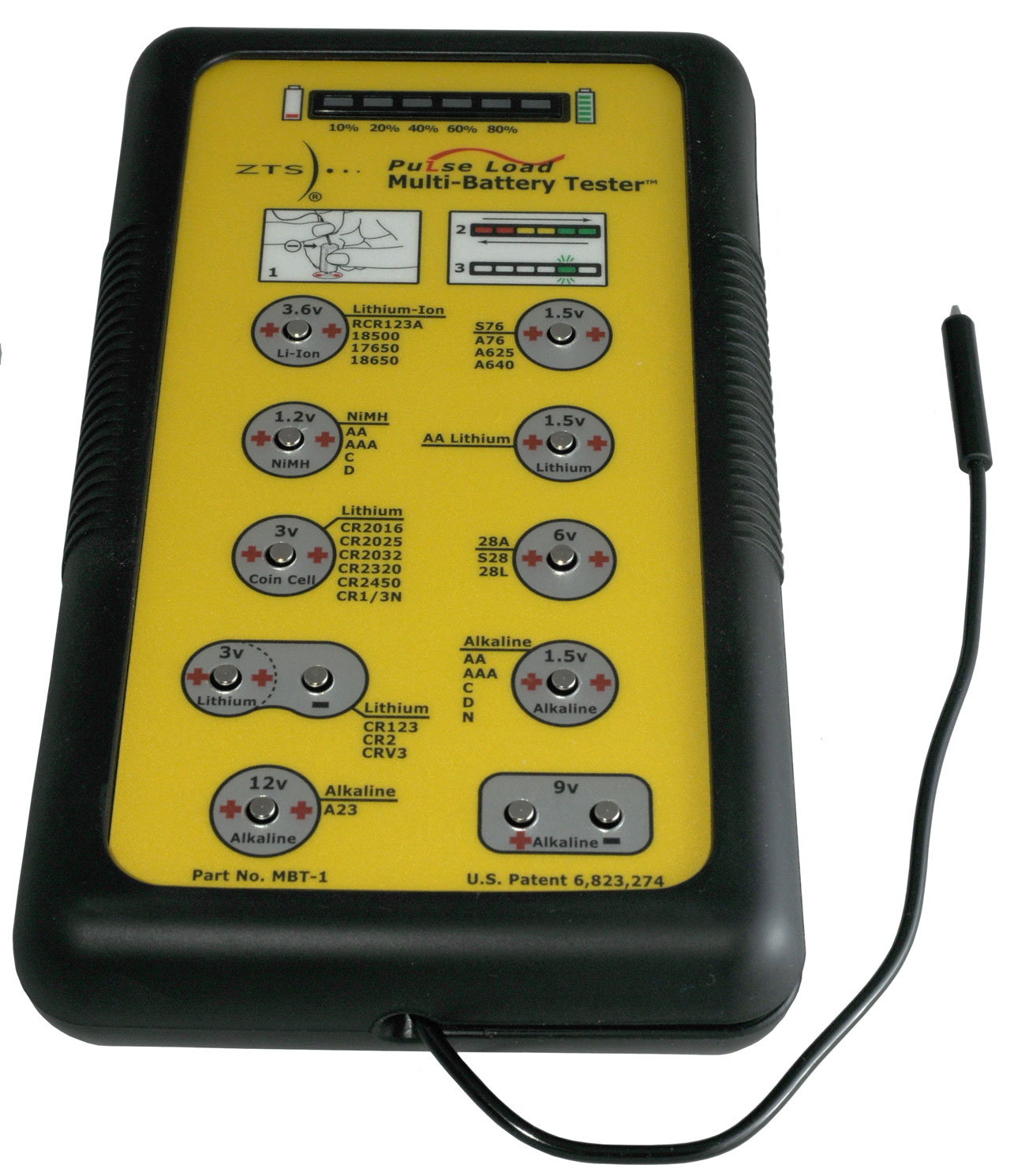
ZTS MBT-1
U.S. Patent 6823274 shows on the
front panel.
Runs on 4 AA batteries.
3.6 V Lithium-Ion
RCR123A
18500
17650
18650
|
1.5V Button Cell
S76
A76
A625
A640
|
1.2 V NiMH
AA
AAA
C
D
|
1.5 V AA Lithium
LS91
|
3V Lithium Button
CR2016
CR2025
CR2032
CR2320
CR2450
CR1/3N
|
6 V 28 Series
28A
S28
28L
|
3V Lithium
CR123
CR2
CRV3
|
1.5 V Alkaline
AA
AAA
C
D
N
|
12 V Alkaline
A23
|
9 Volt Alkaline
|
Army dry battery tester. Works
by measuring loaded voltage.
The set can be carried on a belt and
tests radio batteries, Vietnam era. Uses high current load
to activate Magnesium batteries.
4725784
Method and apparatus for determining the
state-of-charge of batteries particularly Lithium batteries, Feb
16,
1988,
324/427 ; 320/149; 320/150; 320/162; 340/636.15
Uses pulse loading and voltages
measured at various times in relation to the load pulse as well as
temperature correction. Capacity depends on manufacturer as
well as model.
Tests the BA-1574/U Mercury
battery used in the
SDU-5/E Emergency
Survival Strobe Light and the flash rate of the strobe.
BT-2 - Tests BA-1568/U as used in the PRC-90 Survival Beacon
Radio and others, BA-1113/U used on the URC-64 Survival Radio,
the K308A battery used on the
RT-10
Survival Radio, and the BA-1574/U used on the
SDU-5/E Emergency Survival Strobe
Light.
Drop Test
The idea is to drop a AA battery with the + end up on
a reasonable hard surface.
This may work for other Alkaline cells?
A good battery will make a thud sound, no bounces and may stand
up.
A bad battery will sound metallic, bounce and fall over.
How To
Test a AA battery, Easiest Way For Any Battery Fast, Easy!
The comment about testing with a volt meter is wrong. A
no load test does not mean anything.
For a meter test to mean something the battery needs to be
loaded. See the TS-183.
Even load testing does not work well on modern batteries.
Capacity Testing
The idea here is to drain the
battery using a known load until it's voltage is down to the end
voltage and record the delivered Amp hours, or better delivered
Watt hours. Note that when the battery starts the test it's
voltage is highere than at the end where the voltage is the pre
assigned ending voltage. So the early amp hours are at a
higher voltage than the ending amp hours. The early Watt
hours are higher than the ending Watt hours. So reporting
the run time using a load resistor or constant current source is
not as accurate as reporting the delivered Watt hours.
The results for a given battery will be different as a function of
the load.
Coulomb Counting
By measuring the current and the elapsed time the product of
them is how many coulombs (Wiki) have
flowed. Most modern rechargeable batteries use coulomb
counting to determine State of Charge and that can be translated
into remaining run time.
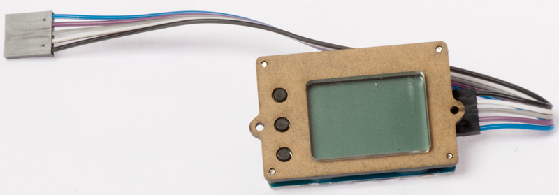
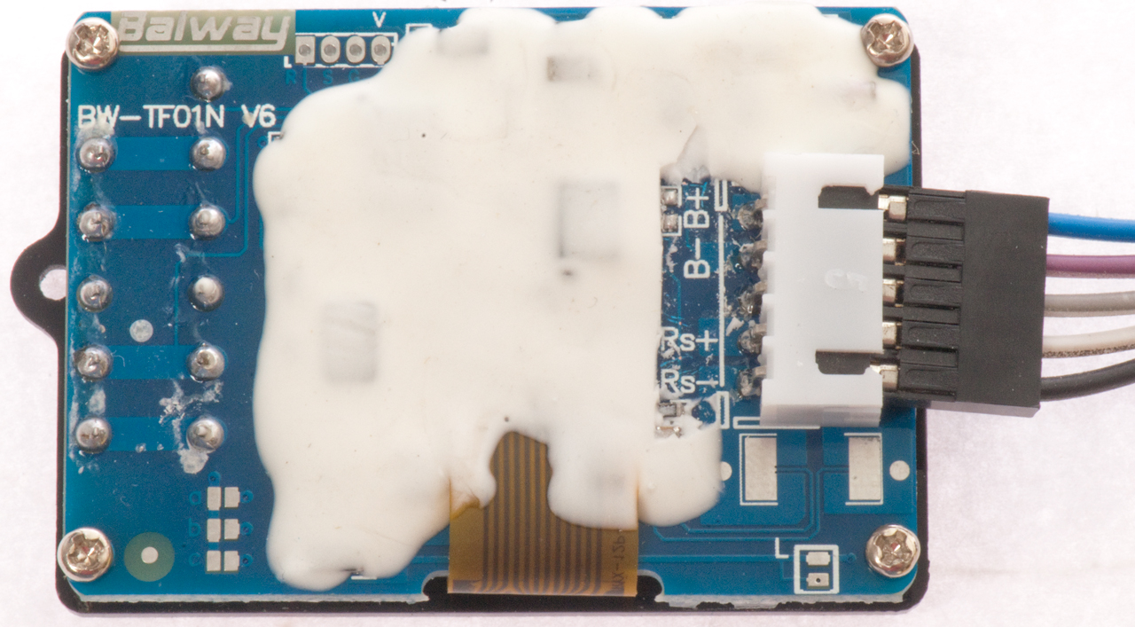
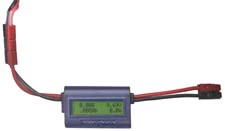
Baiway BW-TF01N Ver 6
Fig 1
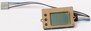 |
Fig 2
 |
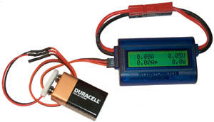
This is a stand alone coulomb counting circuit available on
eBay lu_cytime208
with a title of "Capacity Tester Indicator for 0V-30V Lithium
LiPo / LiIon Battery LCD Display" for about $30.
It can be connected into either a discharge circuit to measure
battery output or into a charging circuit to see how much charge
in put into the battery. Note that you always put more
charge into a battery than you can extract. That's to say
the efficiency is always less than 100%.
This unit has no provision to turn the load on or off. It
is not a load tester nor is it a charger. The Set Voff
voltage is used to control when the TF01N goes into sleep
mode. The idea is to build this coulomb counter into a
battery pack so it's state of charge can be monitored and to
minimize the power used by the TF10N. There is an internal
current shunt that can be used for currents up to 3 Amps and
after that an external shunt can be used up to 50 Amps.
It has no provision for an external power source, but rather
runs on the battery pack it's connected to and that pack needs
to have a voltage of more than 8 volts (up to 50 Volts).
Resistor
A fixed resistor is the load. The load current decreases as
the battery voltage goes down.
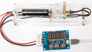
QS-906 eBay title: .5v~12v
Battery Capacity Meter discharge Tester 3.7v 18650 lithium
lead-acid
14 Sep 2016
This unit came from the same eBay seller as the first
non functional one,
but this one has a resistor marked R020
instead of a resistor marked R200 like the first
(improperly assembled) unit.
See below for battery fixture.
|
Discharging an eneloop.
More later .. . .
2.65 AH vs. label capacity of 2.45 AH.
roughly works without calibrating.
|
Fig 5
|
Testing 18650 battery:
15 Ohm 5W resistor (4.1v / 15 Ohm = 273 mA) close to the
300 mA spec
for this Li-Ion battery rated at 1500 mAh,
which tests between 1450 & 1470 mAh (0.777 mAh
shown)
K&J Magnetics parts to make connection to battery
use 6-32 flat head screws.
0.625" dia (RA22CS-P)
and 0.25" dia (R422CS-P)
|
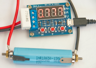
This is also known as a ZB2L3 ZHIYU Battery Capacity Tester
External Load Discharge Capacity Test (I have one of these on
order 29 AUG 2016)
The current sense resistor can clearly be seen with matching
markings on the PCB and resistor of R020.
Function
This is a battery capacity tester that uses an external
resistor as the load to drain the battery. The load
resistor has nothing to do with the device calibration.
Once properly calibrated the load resistor can be changed and
the readings will still be correct.
Load Resistors
The load should never exceed 20 Volts or 6 Amps because of the
MOSFET switch. The MOSFETs are in parallel so the current can be
higher, but I doubt as high as 12 Amps.
There may be a firmware limit of 15 Volts or 3.1 Amps.
The current through the resistor will vary from a maximum value
set by the fully charged battery voltage and resistance.
For example an eneloop AA battery may start out at 1.4 Volts
with a 7.5 Ohm resistor for a current of 0.187 Amps.
The power dissipated in the resistor is V * I or 1.4 V * 0.187 A
= 0.261 Watts.
Since the supplied resistor is rated for 5 Watts this is no
problem, but for more powerful batteries a resistor with a
higher power rating may be required.
Circuit Description
The tester uses a micro controller mounted under the 4-digit
7-Segment LED display.
An 8205s (pdf)
Dual MOSFET each FET speced: 28 mOhms RDSon with a max
rating of 20V or 6 Amps are connected in parallel and switch the
load to battery positive (see Fig 2).
The battery current is sensed by R2 (0.2 Ohms) between the
negative battery terminal and ground.
The battery voltage is sensed by (a guess - hidden circuit under
display) a voltage divider R3 & R4.
Just above the Ah LED is a 0.1" pitch 4-hole pattern that's
probably for in circuit programming of the uC.
The LM1117 (TI)
Low Dropout voltage regulator is set for a nominal 3.3 Volt
output (3.29 actual).
The uC is hidden so don't know make or model.
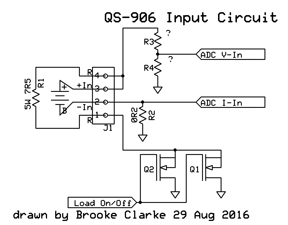
Fig 2 Input Schematic

|
Internal connection between R (J1-4)and +In (J1-3).
Guessing at R3, R4 Voltage divider.
R2 is the battery current sense resistor.
Q1 & Q2 in parallel to switch load to ground.
For all the parts except R2 the marking on the part
matches the nomenclature.
But for R2 the PCB is marked: R020
and the part is marked: R200
Photo
here shows a resistor marked R020.
|
Calibration
Battery and Resistor disconnected.
Step 1.
Display shows: 0A0u (zero Amps and zero Volts), Q1 & Q2 are
open so there is no load on the battery. The battery
voltage drives the microcontroller ADC.
Battery removed and either left open or shorted. Which
works best is TBD
When OK is pressed the zero calibration for both battery voltage
and current is stored (but not saved)
Step 2.
Display shows: 100u (10.0 Volts). Q1 & Q2 are open so no
load on battery or heat in resistor.
Remove battery.
External 10.0 Volt power supply to battery +In and -In
terminals.
When OK is pressed the voltage at ADC V-In is measured and a
ratio stored to get to 10 Volts.
Step 3.
Display shows: 200A (2.00 Amps). Q1 and Q2 are turned on. So if
resistor installed it will heat because of the internal
connection between R (J1-4) and+In (J1-3). But the
resistor can be removed during calibration to avoid overheating
it.
Remove battery.
Connect positive source of 2.00 Amps to -In (J1-2 in Fig 2 above) and the ground to J1-1 (bottom
R).
When OK is pressed the voltage drop across R2 is measured and
stored.
Note the circuit impedance is a few tenths of an Ohm so the
current source does not need to have a high voltage compliance,
like was needed if you mistakenly try to calibrate using the
battery terminals for this step.
Step 4.
When OK is pressed the above values are checked for
reasonableness (how is a mystery) and if they seem OK they are
saved in EEPROM in the uC.
Note this cal only needs to be done one time.
Operation
With the load resistor and battery connected power up the
QS-906.
Press (+) or (-) to see the termination voltage and then press
(+) and/or (-) to set the termination voltage.
Then press OK to start the test.
The first Ah display should be zero.
The first A display should be the battery starting voltage
divided by the load resistor value.
The first V display should be the battery fully charged
voltage minus a little for the effect of the load because of internal resistance.
Error Codes
Err1: the battery voltage higher than 15V
Err2: the battery voltage is lower than the termination voltage
setting.
Err3: the battery is unable to support the load current or of
the test lead resistance is too large.
Err4: the current is too large (current is more than 3.1A.
Example (29 Aug 2016)
eneloop AA cell after calibration using short in step 1 as
above. Results before test finished:
Ah: 3.076 [ended at 7.761 a little more than 3X the actual
value]
A: 0.665 (current still reads 4.01 x too high)
V: 1.24 (DMM: 1.277 V, implies a
current of 1.277 / (7.5 + 0.2) = 0.1658 A
Still not reading correctly. Maybe because of the R2 value
problem (PCB: R020, resistor R200).
Hacking
A way to fix the current calibration is to change the current
used for the cal and tweaking the value to get the current to
read correctly.
I'd like to use this to test BB-2590 military batteries that
are 4 cell Li-Ion, i.e. fully charged at 16.8 Volts, so a bit
above the 15 V firmware limit.
So . . . . by cheating on the voltage calibration by say 17 V
/ 15 V and after finding the correct current for a normal cal
change that by 15V / 17V.
This would require modifying the cutoff voltage by 17/15, but
then the Ah would read correct.
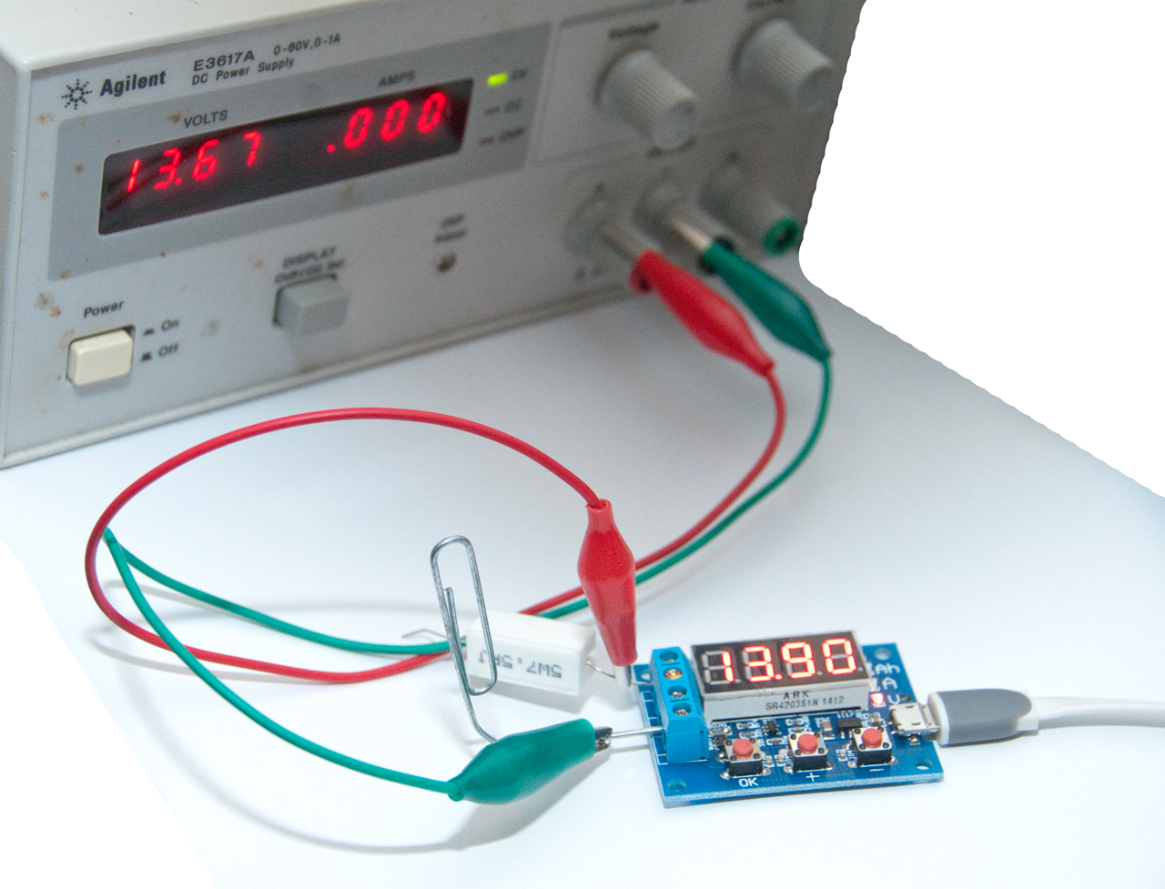
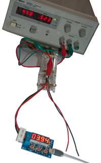
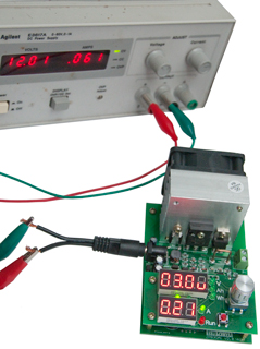
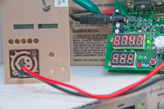
Fig 3 Checking Current
Power Supply on + & - battery terminals
Note PS= 4.50 V, measure 3.94 V because
of resistance of test leads.
|
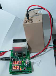
Fig 4 Checking Voltage
Load resistor disconnected.
PS on + and - battery terminals.
PS= 13.76 Volts (just under err1 voltage), measure=
13.98 V.
Note: err1 only happens when tester in run mode.
In startup mode I increased input to 18 Volts and the
tester
displayed it without any error message.
 |
|
|
29 Aug 2016 resolved Prior Problems -
only read for background
Under $5 including shipping from Hong Kong. It
does NOT work as it should, needs updated firmware.
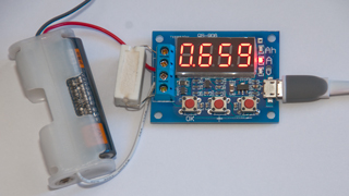
Fig 1 After OAOu:Short, 100u:10V, 200A:2A Cal
actual current is 1.37V/7.5Ohm = 0.182A, Display
current is 0.659Amp, Why?
Operation
An external 5W 7.5 Ohm resistor is switched to the
battery when the OK button is pressed and switched off
when the battery voltage drops below the limit voltage
indicated by Pnnnn.
But
After the battery is connected press + or - to change
the value of P and when correct press OK to start the
test.
YouTube video of QS-906
circuit running.
Maybe calibrated for Voltage (10V ref) and Current (2A
ref) So the tester can calculate the current given
the loaded voltage. If the test leads have too
much resistance:
Err3: the battery is unable to withstand the load
discharge current resistance is too large or line.
I have not yet figured out why some of the error
codes appear or how to do the Calibration. If
you know more contact
me.
The tester has NOT been calibrated and the default
cal is way off.
When testing a Panasonic eneloop pro AA battery with
the 7.5 Ohm load resistor the tester shows: 1.69 A at
1.28 V equivalent to a resistance of 0.757 Ohm
load. So way out of cal.
But when the same battery (fully charged) reads 1.409
V open circuit and 1.403 V with the 7.5 Ohm load
applied. Actual current is V / R = 1.403 / 7.5 =
0.187 A = 187 mA
The battery internal resistance is (1.409 - 1.403) /
187 mA = 0.032 Ohms.
Short current current might be = 1.403 / 0.031 = 43
Amps (but not likely).
Tried cal (holding down all 3 buttons then connecting
power. After start up displays: ---- (indicator
for Calibration mode), 0.004 (maybe offset voltage) ,
OAOu (maybe zero Amps & zero Volts)
when OK is pressed the display changes to: 10.0u when
OK pressed again display is 200A, and when OK pressed
again reverts back to Ah -> A -> V -> Ah
cycle. Doing the cal requires a power supply
that can deliver both 10.00 Volts and 2.00 Amps.
But after trying to do the cal first with 10V and 1A
and twice trying 10V and 2A the cal fails, i.e. when
testing the eneloop shows 1.8 Amps, way too high.
Also tried with current in negative direction, but
still get 1.8 Amps on the eneloop, not the 0.187A is
should be. Maybe some factor of 10 error?
Note: with the supplied 5W 7.5Ohm resistor when the
input is 10 Volts the power in the resistor is 13.3
Watts, and when 2.0 Amps are flowing the voltage drop
across the resistor is 15.0 (the max rated input
voltage) and the power in the resistor is 30 Watts.
This means the calibration must be done very quickly.
Maybe the Ah display is showing 10X the actual
capacity. Will test an eneloop to completion to
see if it comes our near 2.4 Ah X10 = 24 Ah.
The QS-906 shows 1.36 Volts and the DMM reads 1.348
Volts on the screw terminals. Shows 1.741 Amps
Voltage drop across the 7.45 Ohm resistor is 1.308 for
a current of 1.308 / 7.5 = 0.174 Amps
Note current is reading 10.0057 X higher than actual,
so it looks like a 10x error.
Next to see how the battery capacity compares with the
MH-C9000
(tested at 1.0 Amp load, but can be rerun at
something closer to 0.174A.)
If 2.4 Ah capacity and 0.174A load then 13.8
Hours to discharge. About 12:30 now.
About 1:00, was not watching, the mode indicator LED
is flashing for Ah, A and V instead on being on
steady. Displays: 1.003 Ah, 1.692A (actually
0.1692A) and 1.31 V (cutoff set to 1.20 Volts).
Do not understand whey flashing. Will let run
longer to see if V display (and DMM) go down to 1.2
V. Load resistor has 1.264V voltage drop (
0.168A) so still connected.
At about 11:00 pm the voltage was 1.24 V so not
done. Next morning very fast flashing and the
capacity shows at 19.71 Ah. Pressing OK twice
shows the voltage as 1.26, i.e. the cell has recovered
a little. Pressing OK some more times to restart
testing shows: 0.000 Ah, 1.583 A & 1.23 V.
So, it looks like the reported capacity might be 10x
the actual capacity. Now testing an eneloop at
200mA discharge to see what capacity it has.eneloop
has 2480 mAh capacity when discharged at 200 mA, so
the19.71 Ah (divided by 10 = 1.97 Ah is still way off.
Tried calibration:
1. Short, 0A0u -> OK
2. 10 V, 100u -> OK
3. 2 Amps, 200A -> OK
but when fresh eneloop battery installed the displayed
current is 0.669 Amps, much higher than the actual .174
Amps (384 % off).
The next day the display shows:
Ah: 7.125 (clearly much higher than 2.4 the actual
capacity)
V: 1.26 |
Filament Flashlight Bulb
The resistance of the bulb changes in a non linear way with the
battery voltage. The bulb gets dimmer as the battery voltage
gets lower. How dim does the bulb need to get to say the
battery is dead? Kind of a fuzzy feely thing maybe not the
best capacity test method.
Constant Current
When a constant current load is used the delivered Watt hours are
directly proportional to run time. This is the most constant
load type.
Constant Power
Switching Mode Power Supplies, like used in most modern battery
powered devices consume what's pretty close to a constant power in
Watts. This means at higher battery voltages they draw
smaller currents than when fed lower battery voltages. This
is the oppsite of the resistor load.
Electronic Load
A transistor or other device can have it's resistance varied
electronically and so acting as a programmable load. The
mode of operation can be as simple as looking like a resistor,
or a more useful mode looking like a constant current.
Amrel EL1132
Electronic Load
This is a bench top electronic load
test instrument that can be set to look like a constant
resistance, current, power or voltage load. By using a
computer to control the load and read back the battery voltage and
current almost any test sequence can be accomplished. There
is a low voltage limitation of 2.5 Volts.
ZPB30A1 "Constant Current
Electronic Load 9.99A 60W 30V Battery Discharge Capacity
Tester"
The quoted title of this paragraph is the same as the eBay
title for this made in China tester. eBay seller ayanhu81
(about $20). The same seller also has a "Four Wire Battery
Holder Battery Resistance Test for 18650 26650" that works with
the capacity tester. See a nicer BF-1L
4-wire battery holder below.
Note this unit has no charging capability, it's only a constant
current load or capacity tester. Can also be used to test
sources like wall warts, power
banks, &Etc.
Technical
Review -
Youku video (Mandarin): Use as
Constant Current Load -
Youku video (Mandarin): Use as
Battery Capacity Tester -
Fig 1
|
Input power: 12 VDC <= 0.5 (0.1 typ)
DC power connector: 5.5 x 2.1 mm.
Power up display: 03.0u Volts & 0.21 Amps
|
Fig 2 as received was in Constant Current
Load mode (Fun 1)
|
The top display stays fixed on Volts
Before inserting the power plug,
hold down the red button, then plug in power.
Turn knob so that Fun 2 appears, then press knob.
unplug power.
Now unit will come up in Battery Test (Fun 2) mode.
The other parameter that shows up after the Function is
the beep mode on or off.
|
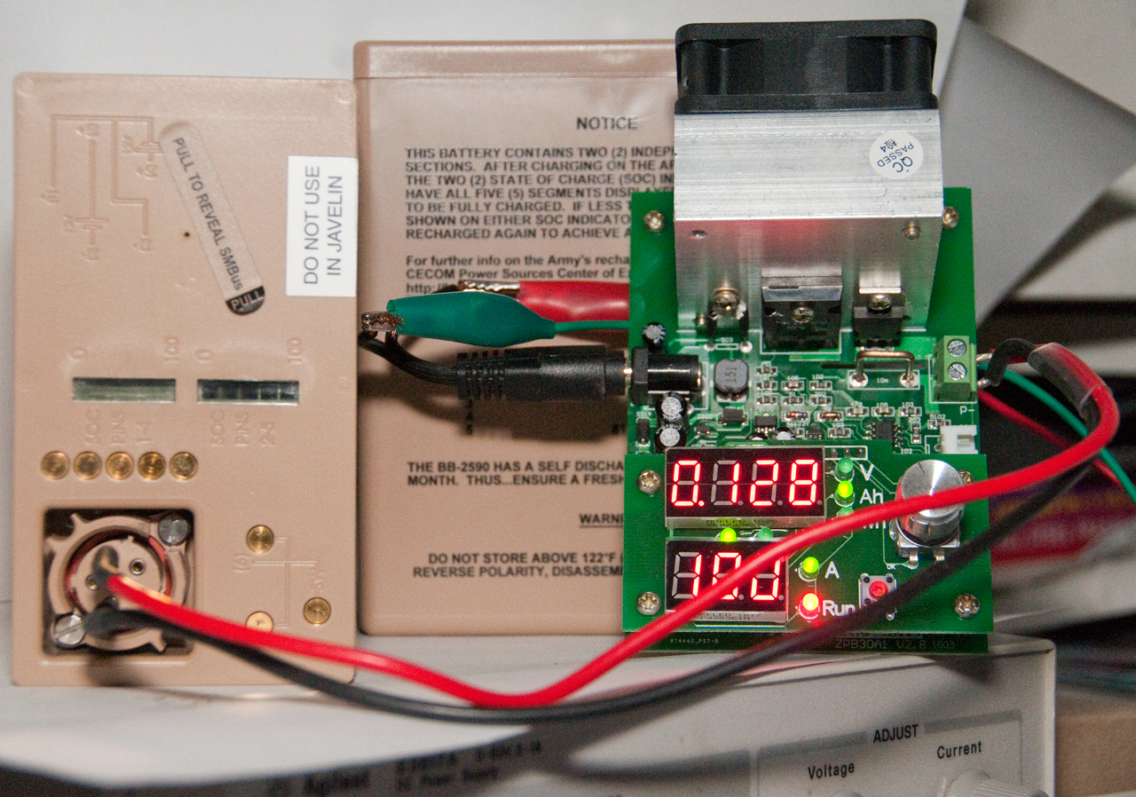
Fig 3 after changing
into Fun 2: Battery Capacity mode

|
1.00 Amp constant current load, 14.4V cutoff
The top display rotates between: Voltage, Ah & Wh . .
. .
This battery is a 4S Li-Ion BB-2590 (BT-70791BK1).
Probably 225 Wh, but we'll see.
Note the voltage displayed (16.07) matches what I read
with a FLuke 87 DMM (16.07), so for a 1 Amp load and these
short wires the IR loss is about zero.
|
Fig 4 At end of capacity test
|
Note the State Of Charge bar graph on battery shows 1 bar
here and in fig 3 above shows all bars.
Tester reads 6.747 Ah, 15.18V & 102.4 Wh
Test was run with 1.00 Amp load & cutoff @ 14.4V.
|
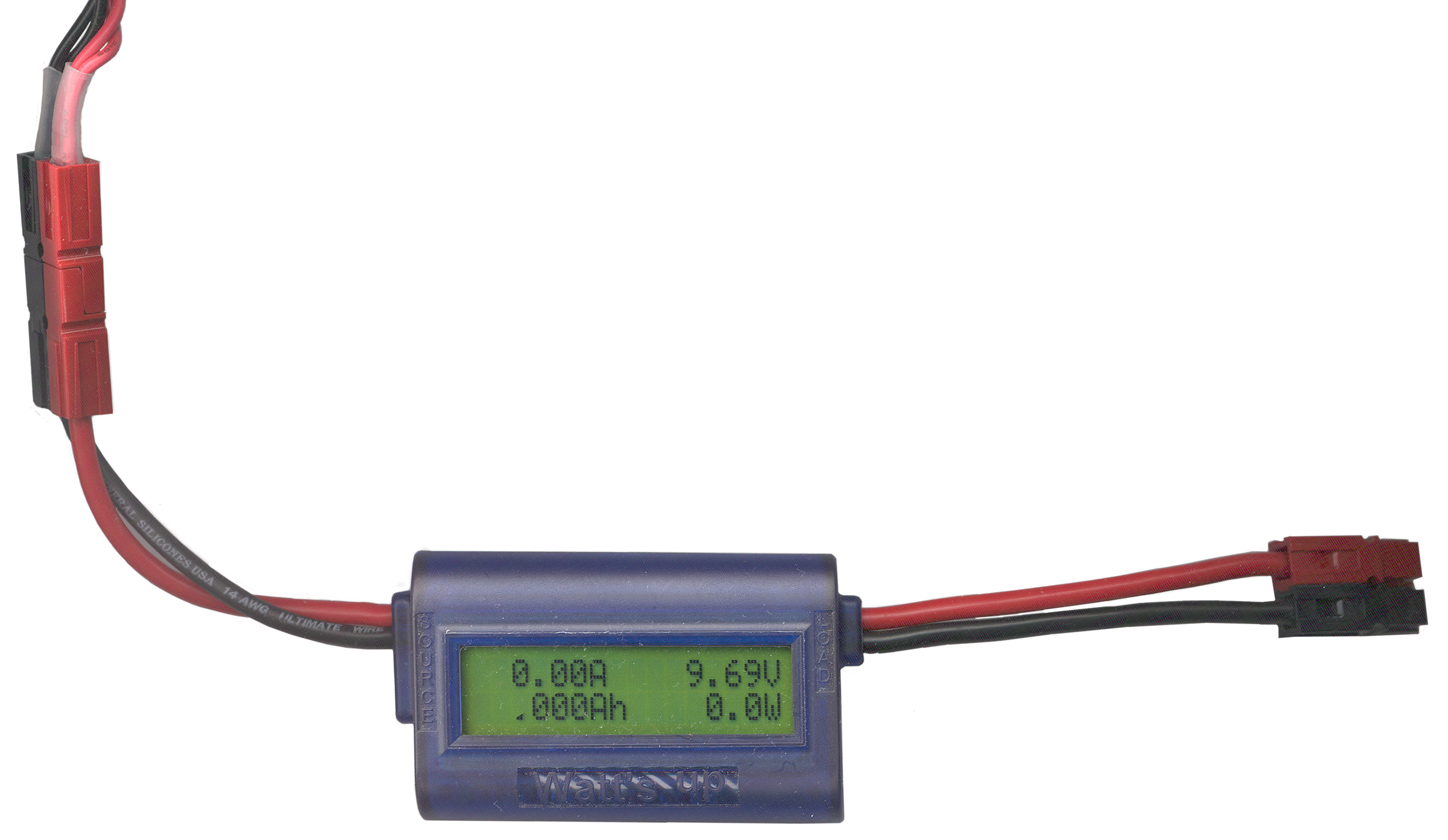
This is a handy gadget that not
only measures voltage and current but also has an internal clock
so that it can count coulombs. This allows displaying Amp
Hours and Watt Hours. It's a natural to have power
pole connectors on the input and output. A battery might
be the input and a motor might be the output, or a battery
charger might be the input and a battery on the output.
For measuring voltages below maybe 4 volts an external power
supply is needed. There's a 3 male pin connector next to
the SOURCE wires where an external battery can be connected to
power the Watt's Up when testing below 4 Volts.
wu100v2_user_manual.pdf
(at
RC Electronics)
|
|
Watts
Up Coulomb counter
|
Aux
battery connected to allow working with voltages below
4.
With test leads shorted there's a reading ov 0.05
volts.
Org : gnd, Red:+9 drawing 5 ma Brn: Reset when
grounded.
Aux
cable at PowerWerx
|
Ni-Cad, Ni-MH or Li chemistry
charger discharger with LCD readout of parameters. Does
packs.
Intended for Ni-MH AA or AAA
cells. Only tests single cells, not packs. Four
independent channels and can do different things to each
channel.
Multipurpose Charger Discharger
Cycler for a number of chemistries with plenty of
adjustments. One battery at a time. Can do packs.
iMAX B6 LCD Screen Digital Lipo NiMh
Battery Balance Charger
1.5v~12v Battery Capacity
Meter discharge Tester 3.7v 18650 lithium lead-acid
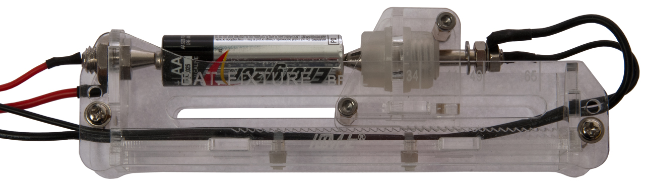
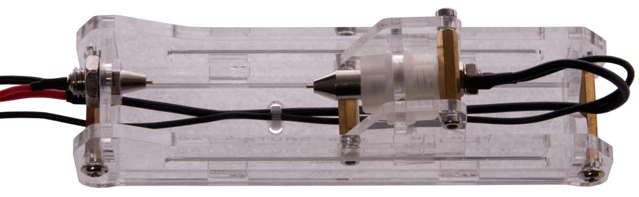
BF-1L Battery Fixture (Single Cell)
This is fixture was laser cut from clear acrylic and the saw
tooth bed has markings for 34, 44, 49 & 65mm long
cells. It is a Kelvin fixture with separate wires for
forcing current and sensing voltage. The negative
terminals are spring loaded. Fastech BF-1L
BF-1L battery Fixture with standard AA cell
on 44mm setting

|
BF-1L battery Fixture w/o a battery
 |
Internal Resistance
Any resistance inside a battery will generate heat during
charge or discharge. It also limits the maximum current a
battery can supply. Classically secondary batteries, like
lead acid, are used for high current applications because of
their very low internal resistance. I tried to measure the
internal resistance of a Leclanché
Battery with a Fluke 87 DMM and
burned out the internal fuse because it could supply much more
current than I expected.
This is very similar to, if not identical to, to concept of ESR
(Wiki
Equivalent Series Resistance) in capacitors. A high ESR
means that the capacitor can not do as good a job as another
capacitor with a much lower ESR.
The use of an amp meter to "Flash Amp"
test No. 6 dry cells is based on looking for both charge and low
internal resistance.
Examples
Table of Maximum
Available Current for RC rechargeable battery packs
nominally 7.2 Volts.
Internal Resistance is approximately Nominal Voltage / Flash Amps -
"D" cell 1.5 V / 13A = 0.12 Ohms (but the resistance of the
Flash Amp meter needs to be subtracted.)
Ryobi Tire
Inflator Battery Internal Resistance - both are "18 V, 4.0
AH";
Not much different?
Model
|
Voc
|
Ri
|
Flash
Amps
|
| PBP005 |
20.7 |
0.0451 |
459
|
PBP004
"Hi Performance"
|
20.5
|
0.0432 |
474
|
Black
& Decker LST522 String Trimmer - these are all standard
batteries, comparing 2.5 AH with 4.0 AH batteries.
SM8124 (20R) Battery Impedance Meter
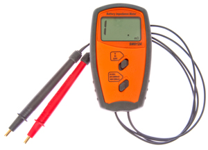
I let the smoke out of my ESR-Cap meter when trying to measure
the internal resistance of some 7.2
Volt RC batteries, so found this unit from eBay seller hkwisefield
(eBay search for Internal
Battery Resistance Tester).
The top switch is Off-Ohms-Volts and the bottom switch is
100V/200mOhms-20V/2 Ohms- 2V/20 Ohms.
There are two wires to each test probe (i.e. Kelvin
connections) to cancel test lead resistance. But only a
single terminal.
The test signal is about 1 kHz at more than 1 VAC.
By using an AC test signal the meter can use AC coupling for the
resistance measurement keeping DC out of the test circuitry.
The AC test signal also has the advantage of not being
influenced by voltages caused by thermal differences at metal
junctions.
To replace the 9V battery peal the rubber case from the top
side just enough to get to the battery compartment.
PS this meter is also called "20R" and there is a very similar
meter called SM8124 that's for measuring UVA and UVB light.
For a practical application see testing RC Car 7.2 Volt battery
sticks for Maximum Current by
measuring battery resistance.
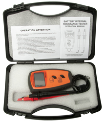
SM8124A Battery Impedance Meter
The "A" version adds Kelvin
connections to replace the single terminal connection used
on the SM8124 version. So now each probe has two spring
loaded terminals. This should improve the accuracy by
eliminating the probe to DUT resistance.
Have this on order (Dec 2021, Rcvd: 2022 Jan 5) in the hope
of testing the internal resistance of some tool batteries, like
the Riobi
and Black
& Decker.
eBay title "Battery Resistance Voltmeter Internal Impedance Meter
LCD Rechargeable SM8124A" from seller tangzhimin1008.
Came in a hard carry case which I like better than the soft carry
case shown in the eBay ad.
Uses a single 9V battery.
Resistance test drive (measured with Fluke 87V DMM)
Ohms
Range
|
ACV
|
Hz
|
20
|
1.29
|
1042
|
2
|
1.64
|
1042
|
0.2
|
1.69
|
1042
|
Fig 1
|
|
EVB ESR/Low Ohms
Meter
 You can use one of the
hand held capacitance ESR meters
to measure the resistance of individual cells and of battery
packs. But first a couple of modifications need to be done.
You can use one of the
hand held capacitance ESR meters
to measure the resistance of individual cells and of battery
packs. But first a couple of modifications need to be done.
(1) The two large protection diodes need to be removed from the
PCB. They are located near where the banana jacks are wired.
(2) A SPST normally open push button switch is added near the tip of
one of the test leads and in series with the lead. Across the
switch place a 470 ohm resistor. When the probes are first
connected to a live battery the 470 Ohm series resistor pre charges
the internal non polarized blocking caps without hitting them with a
really fast rise time pulse, thus tending to protect the internal
circuitry.
To make a measurement first do the
calibration by:
- push both probe tips onto a good conductor (like on a PCB) [do
not touch the sides of the probes together since you will not
get as good a connection, same for when actually testing, use
the points].
- press the SPST probe switch and while holding it press the
meter cal button.
Then to make a measurement:
- press both probe tips onto the contact points to be measured,
then, press the probe tip SPST button to make the measurement.
The meter I'm using from
EVB in
Portugal, is the same circuit designed by
Bob Parker
and sold by
Dick Smith
Electronics in Australia as a kit. I saw mention
of battery testing at
Hints for techs
using Bob Parker's ESR meter(kit)... and an email from
Bob suggested the switch and resistor to reduce the likelihood of
damage to the meter.
I'll be using it to
test the battery
packs for my 5590BA Battery Adapter.
I haven't tested the 4328A on a
battery but it's my recollection that it's rated for up to 150
Volt batteries. More modern meters are limited to 42 Volts
because of human safety considerations, so there's still demand
for the HP 4328A meter for testing between 42 and 150 Volts.
The ESR-Cap meter can easily
measure internal resistance. See the example
table of data. But the
early versions without internal protection circuitry can be
damaged if an attempt is made to test a capacitor charged to a
very high energy level or connected in reverse polarity.
Dynamic Resistance
This is a concept first patented (3873911)
by Champlin for testing lead acid storage batteries. He
choose a square wave test frequency of 100 Hz and measured the
battery internal resistance.
Snap-On patented (5773978)
an improved version where they used better circuitry to get more
sensitivity and resolution.
Snap-On patented (7657386)
a Battery Service System that connects to the battery but checks
the alternator and starter.
1. System Test
2. Battery Testing & Charging
3. Starter Test
4. Alternator Test
5. Noise Test
6. Multimeter
Shelf Life
New for me Oct. 2007 are the "Ready
to Use" rechargeable batteries. Sanyo eneloop brand in AA
Ni-MH format. Capacity of 1.9 to 2.0 AH. Testing
capacity can be typically done in less than 24 hours, but shelf
life may take months or years. See the eneloop
Ready To Use
battery web page for the test plan.
self-discharge (
Wiki)
causes most rechargable batteries to loose charge just sitting.
Also see the paragraph on
Li-Ion battery maintenance and the associated video.
Analyzers
A battery analyzer has the capability to both charge and
discharge a battery and make measurements of it's parameters, so
is more than either a battery tester or a battery charger.
Cadex C7200 is a 2-bay battery analyzer mainly built for
Ni-Cad, Ni-MH, lead-acid but also can do some Li-Ion battery
stuff.
The HP 6633A can work in two quadrants and so can both charge
and discharge a battery so software could be written to use it
as a battery analyzer (or a battery simulator).
YouTube - 6632B battery
test software - 6632 is 20 V @ 5 Amps, the 6633 is 50V @ 2
Amps. testing 1850 3 Ah cell.
Christie makes a number of battery analyzers, like TS-3997/U
NSN: 6625-01-227-9615. This appears to the a relabeled
CASP/2000 battery tester aimed at Lead-acid and Ni-Cad aircraft
batteries. Not Li chemistries.
Flash Amps
This is the current a battery can
source when a load of 10 milli Ohms is applied for 200 milli
seconds. So far the only mechanical relay I've found that
can handle 40 Amps (needed for "D", "F" and
No. 6 dry cells)
with
a contact resistance will below 10 milli Ohms is the one
used in car starter motor circuits typically rated for 400
Amps. Solid state devices have way too much
resistance. A method of getting the required load is to
connect just under two feet of 14 AWG copper wire across the
terminals. The problem is only connecting it for 200
milliseconds and then disconnecting. If left connected
longer serious problems with the battery or load may occur.
Links
Back to Brooke's PRC68 home, Products for Sale, Battery,
Battery Chargers, Battery Patents, Leclanche,
No. 6 Battery,
Military Information, Personal Home page
page created 13 Oct 2007.
 Aug 2007 -
Added test jack table to
TS-183 web page so that the Radio Shack load resistors could be
compared to the TS-183 load resistors. The Radio Shack
tester showed a 9 volt battery as good yet the battery would not
work in the Stamps.com postal scale. The TS-183B showed the
resistor as bad after abut 5 to 10 seconds. There's a 100%
difference in the load resistors for this voltage. Need to
check the others.
Aug 2007 -
Added test jack table to
TS-183 web page so that the Radio Shack load resistors could be
compared to the TS-183 load resistors. The Radio Shack
tester showed a 9 volt battery as good yet the battery would not
work in the Stamps.com postal scale. The TS-183B showed the
resistor as bad after abut 5 to 10 seconds. There's a 100%
difference in the load resistors for this voltage. Need to
check the others.