Northern Telecom GPS Satellite Simulator STR2760
© Brooke Clarke 2011Background
Description
Velocity: +/1 120km/s
Acceleration: +/- 3600m/s2 (350 g)
Jerk: +/- 5,000 m/s3 (500 g/s)
Guess as to how it functions:
An external computer uses IEEE-488 to send commands to the two VME computers in the unit. The two VME computers have custom ROMS for (1) VME operation and (2) GPS signal simulation. The parameters passed to the VME computers describe what signals each of the 5 L1& 5 L2 signal generators are to simulate probably including doppler shiift profile as well as orbital elements, PRN assignments for each signal generator. Once loaded and turned on the simulator would continue to run until unplugged. Note 5 signals are enough to fill up all the channels of the PLGR GPS receiver. But they would only be available while overhead and after a couple of hours would all set. It would take 3 or 4 of these to simulate the full GPS constilation.
This type of unit may have been used to caputer the RQ-170 Sentinel aka "Beast of Kandahar" (Wiki) spy drone.
From Jane's
GPS test equipment (United Kingdom), AIRSPACE MANAGEMENT - NAVIGATIONAL AND ELECTRONIC LANDING AIDS
Corporate structure
Formerly known as Nortel plc, a subsidiary of Northern
Telecom Inc of Schaumburg, Illinois, USA, the company was
acquired by Bowthorpe plc in 1997 and renamed Global
Simulation Systems Ltd (GSSL).In 2000, the company changed
its name to Spirent Communications (SW) Ltd.
Product
A range of simulators has been developed by Spirent
Communications for testing GPS equipment.The STR 2760
multichannel GPS simulator is supplied as a turnkey system
including the computer workstation, signal generator and all
operating software. The unit can be configured for C/A code,
at L1 and L2 and, with the SAAS upgrade kit (for authorised
users), Y code simulation. Up to 20 channels can be
installed in one chassis. The simulator can also be supplied
or upgraded for Differential GPS and attitude testing.
Other options for the STR 2760 include a multimode, multichannel jammer, closed-loop real-time upgrade, Ethernet interface (for aiding and logging data), various receiver interfaces and Wide Area Augmentation System (WAAS) simulation.The STR 2720 and STR 2775 are single-channel GPS simulators developed for maintenance and production testing. These units enable GPS receivers to be checked and provide the opportunity for automated testing of equipment.
DOA
 |
 The Blue "Host" connector is HP-IB (IEEE-488) interface to control computer The fan runs on 24 VDC. |
|||||||||||||||||||||||||||||||||||||
Inside
Top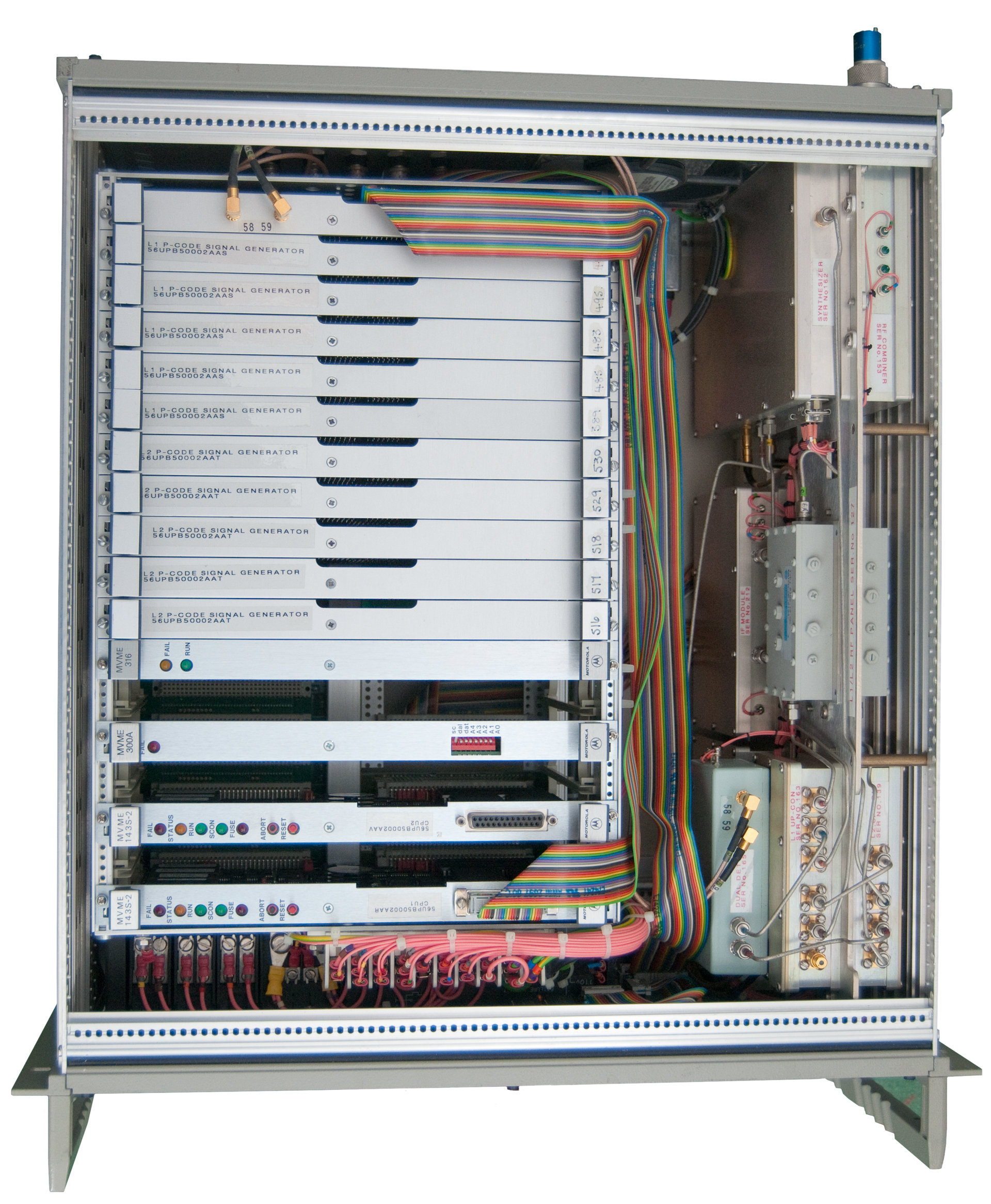 |
VME Card
Cage Wiki: VMEbus
|
|||||||||||||||||||||||||||||||||||||
VME GPS I/O card |
This card is the source for
the ribbon cable that drives the front panel LCD. In the lower left are 2 ZN439 8-bit A to D converters. That means the "58" and "59" coax cables are inputs to the VME system. On this, and I think all other, VME cards the upper left connector is for the analog GPS signals and the upper right connector is for the digital intercard communication. |
|||||||||||||||||||||||||||||||||||||
VME bus L1 P-Code Sig
Gen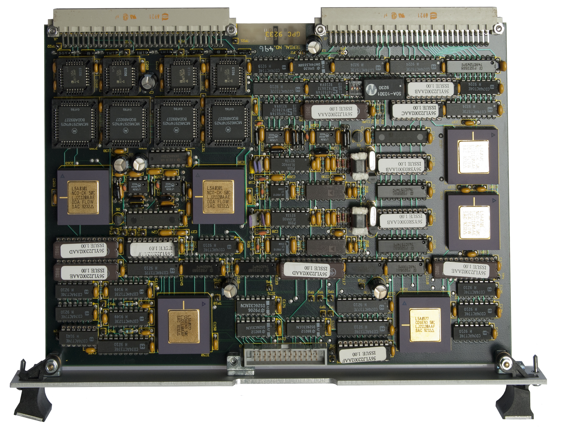 |
The VME cards for L1 and L2
appear to be identical in terms of their layout and chip
compliment. Although I haven't checked my guess is that there might be differences in the ROMs. |
|||||||||||||||||||||||||||||||||||||
VME bus L2 P-Code Sig Gen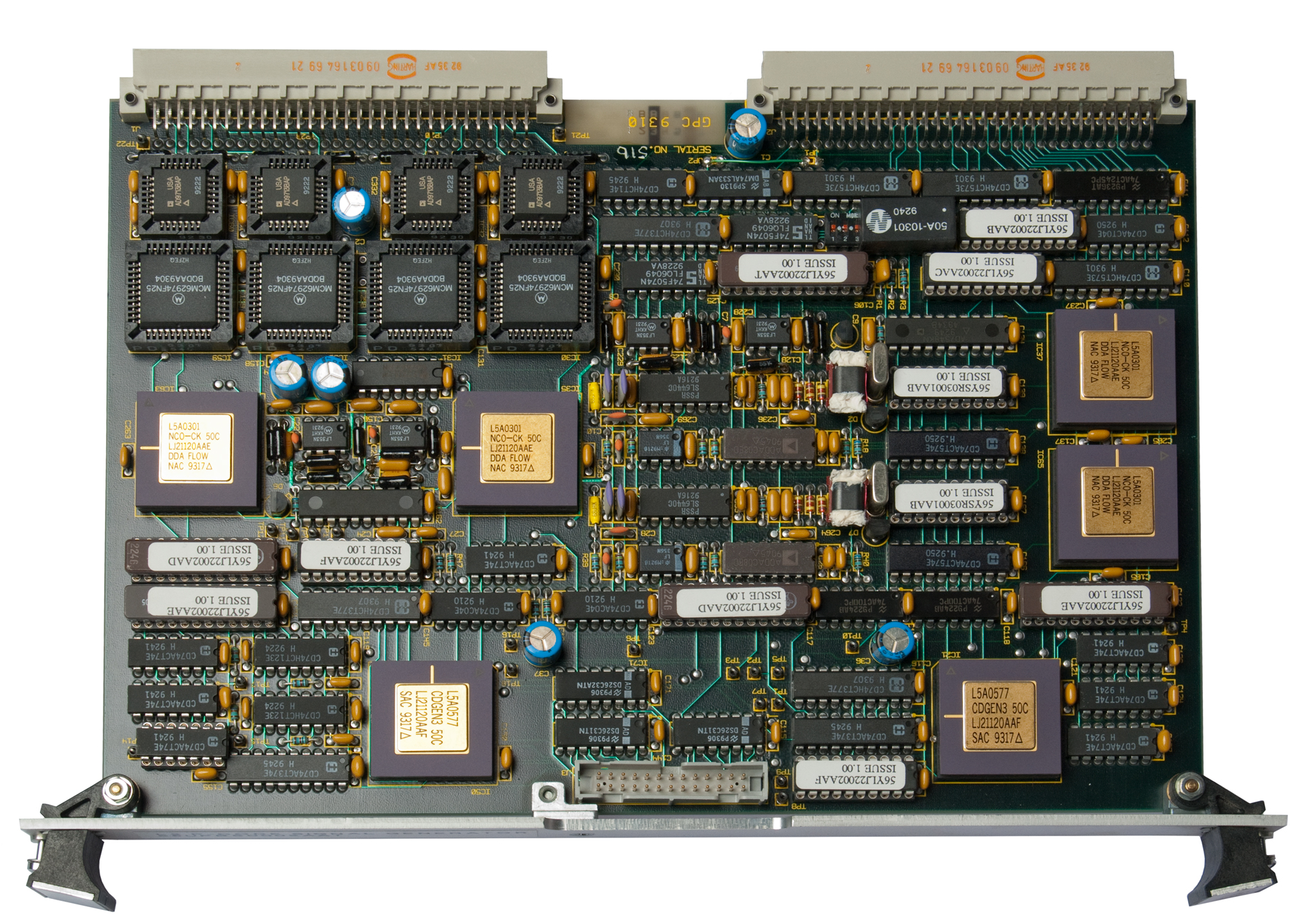 |
In the upper left there are
4 each AD9713B
- 12-Bit, 80 MSPS, TTL Compatible DAC just below them are 4 each MCM62974 - 12 Bit Synchronous Static RAMs In the rwo below them are 4 each "NCO-CK 50C" (guess) Numerically Controlled Oscillators at the bottom of the VME card are 2 each CDGEN3 50C (guess) Carrier Data Generators |
|||||||||||||||||||||||||||||||||||||
MVME 143S-2 Motorola VME
CPU board with STR2760 ROMs ROMs: U5: STR2760 U3: STR2760 U2: VME1439 U1: VME1439 |
This is one of the two CPU
cards in this system. Probably one for L1 and the
ohter for L2 signal generation. |
|||||||||||||||||||||||||||||||||||||
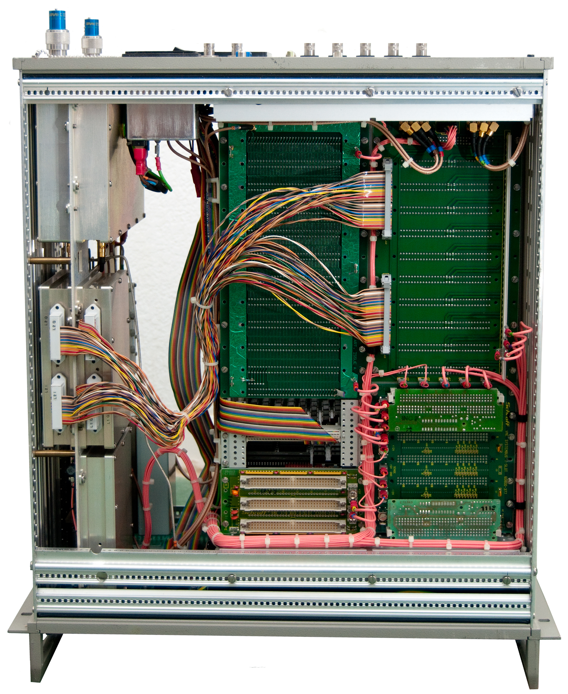 |
Inside Front The black box is a power supply rated 5V/60A, +12V/12A, +5V/12A. There is continuity between the line cord and the 110VAC input, but there appears to be no output. EN60950 BS7002 LR91780 p/n: E25025 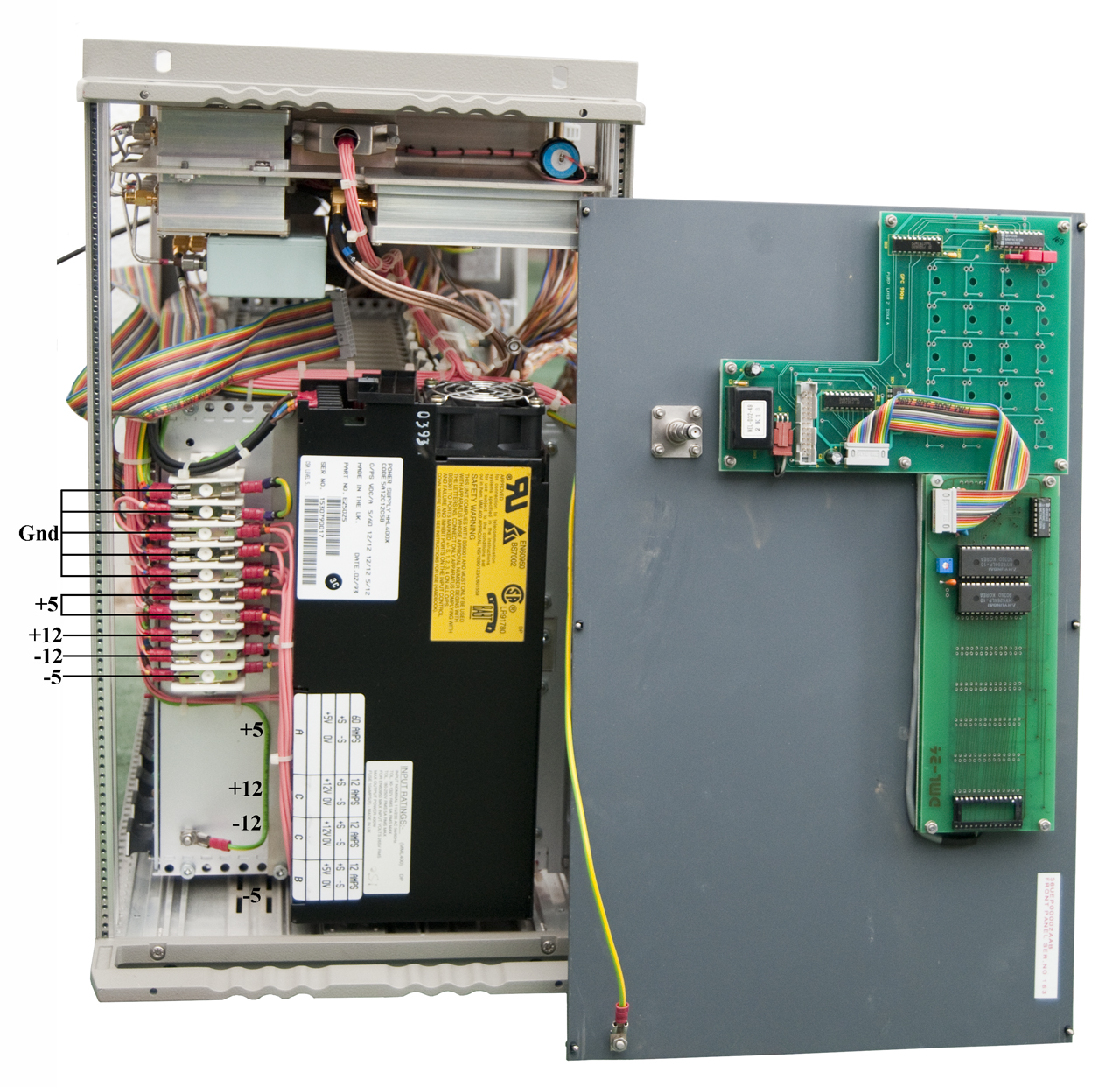 The PCB for the front panel must be a standard unit that supports a number of LED/Buttons and this implementation just has the LCD. |
|||||||||||||||||||||||||||||||||||||
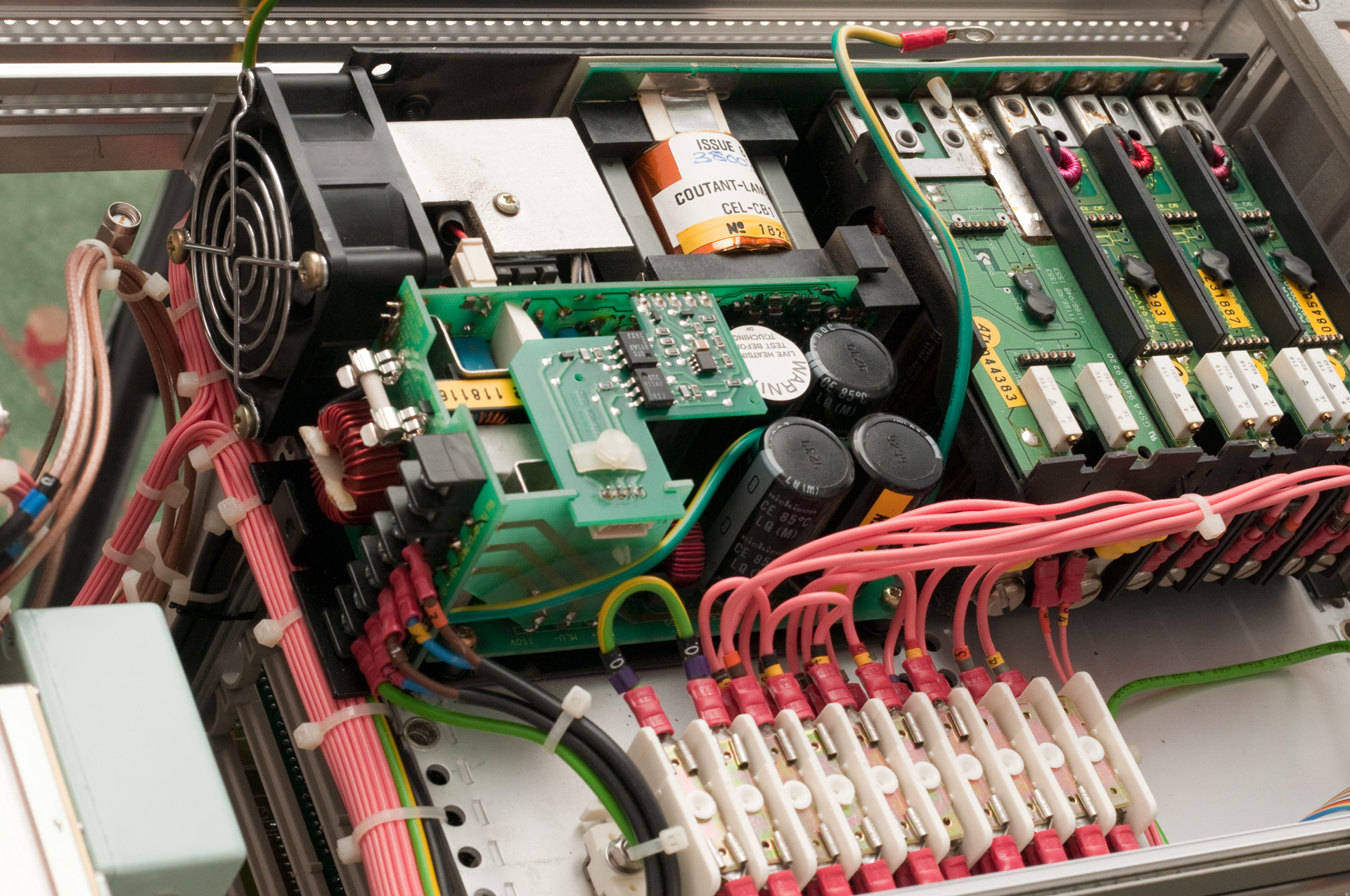
Coutant Lambda Omega MML 400 Power SupplyTo get to the input fuse
inside the MML 400 power supply it's necessary to:
OperationThe input 120 VAC is
rectified (how?) to DC less than 200 V.
That's used to power an oscillator that drives T1 primary. T1 secondary powers the output modules. Input/Main ChassisThere are 6 Printed
Circuit Boards.
InputLine Hot -> Fuse FS70
half of L70 -> Main Board
Neutral --> 110 ----> half of L70 -> Main Board Angle Boardpasses MLU+, MLU- &
110(dot) to Main Board
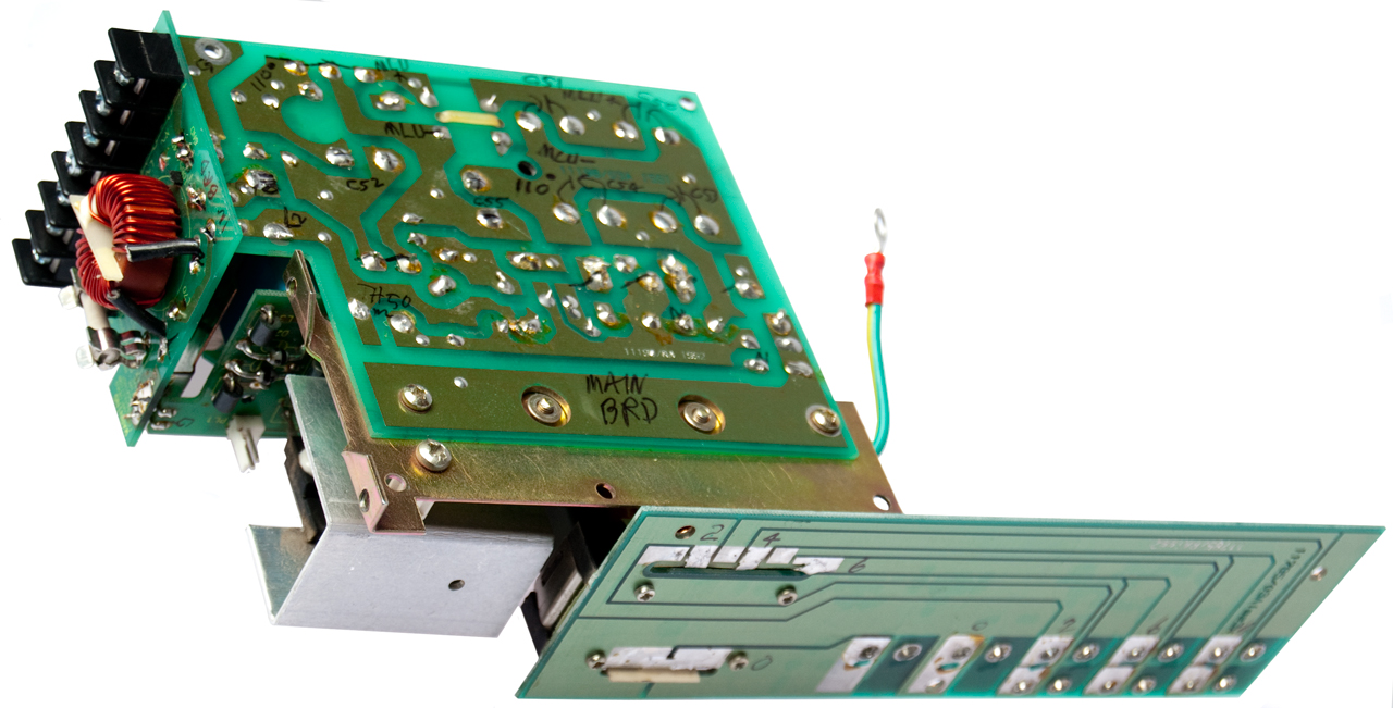
Main BoardLine Hot -> TH50 (37
Ohm) ->
MLU+ <- L50 <- C50, C51, C53, C54 (200 WV) <- D1 cathode, TR1 drain MLU- <- C52, C?? <- D2 anode TR2 source (by way of ferrite bead & 1T primary of T3 Active Board (MLU Rectifier Board)Has D1, D2, TR1, TR2,
T3, PL1 (fan )
Primary of T1 main high
frequency transformer
Opto BoardConnected to Active
Board
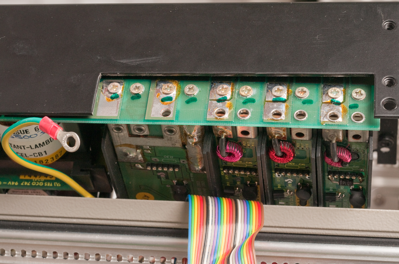
Output BoardSecondary of T1.
Provisioin for 7 outputs, on my version T1 only has 4 outputs, one very high current & three lower current outputs. |
||||||||||||||||||||||||||||||||||||||
 |
The input protection fuse
can be seen next to the fan. It tests good, so
there's some other problem. The fan runs on 12 VDC. |
|||||||||||||||||||||||||||||||||||||
|
Next remove all the output
modules.
On the bottom of the power supply there are a 5 pairs of screws, 3 pairs are for the narrow modules and 2 pair for the double width module. On the back there is a insulating paper held by a plastic fastener which when squeezed easily comes out exposing the input connecting screws shown below. |
||||||||||||||||||||||||||||||||||||||
 |
||||||||||||||||||||||||||||||||||||||
|
To remove the input module
from the sheet metal chassis you need to use a real
Philips #1 screwdriver (a nut driver has too big a shaft
to get past power supply parts.
|
||||||||||||||||||||||||||||||||||||||
 |
Input Wiring Table
This is for the Opto Isolated mains failed & Inhibit options. |
|||||||||||||||||||||||||||||||||||||
 |
 |
|||||||||||||||||||||||||||||||||||||
| I'm
thinking of using external power supplies (+5, and two
floating 12V) for power, thus bypassing the the dead
supply module. Another option would be to use an
external source of an H.F. signal (what frequency?) to
drive the output transformer. |
||||||||||||||||||||||||||||||||||||||