Stanford Telecom 5001A Navstar Test Transmitter
© Brooke Clarke 2000 - 2024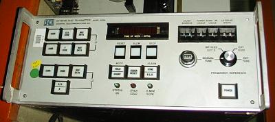 |
 |
|
|
A former employee of Stanford Telecom told me this was used to
test the large scale integration GPS receiver chips that Stanford
Telecom made. In particular this test transmitter was used
to measure the jitter between channels on their GPS receiver
chips. The Quantic 5200 GPS
receiver uses the Stanford Telecom GPS receiver chip set.
The Northern
Telecom GPS Simulator STR2760 is a 10 channel (5 ea L1 & 5 ea
L2) simulator that does C/A & P-Code. There are I
& Q modulators for both L1 and L2 frequencies. That's
to say it will generate enough signals to cause a GPS receiver
to display all it's functions.
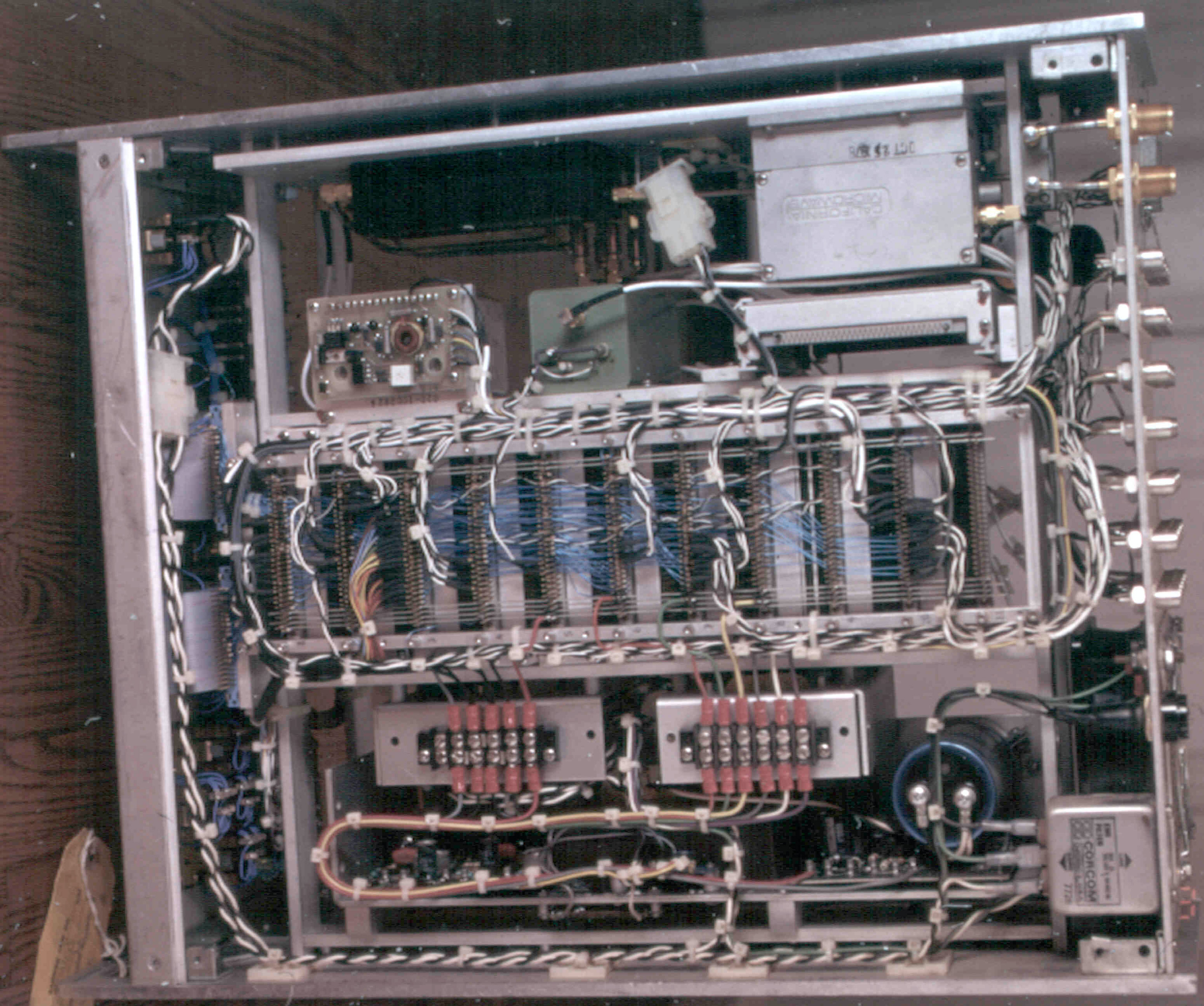
This is a late 1970s GPS signal generator. Many boards are
done with wire wrap. It contains 3 commercial power
supplies, Boards A-1 through A-10, and the Microwave
section. The design of this unit follows the ICD-200
spec in design.
To view *.dwg drawings you need the Autodesk .dwf viewe
Stanford Telecom also made the 7200 GPS simulator from 1989 to 2000 [ION Museum: Stel Satellite Signal Generator (SSG)]
Front Panel: Fpnl5001A.dwg
Rear Panel: Rpnl5001.dwg
NAVSTAR TEST TRANSMITTER
MODEL 5001A
MANUFACTURED BY
STANFORD TELECOMUNICATIONS INC.
P.N. 200-102721
SERIAL NO. 004
Top web page Top_View.dwg
Bottom web page
5001_Blk.dwg
ICD-GPS-200 is the controling document for the GPS system.
Figure 3-2. Generation of Codes and Modulating Signals -
many of the names in this diagram match the card names in the A1 to A7 range. It is clear to me that ICD-GPS-200 was the source document for this very early GPS transmitter used for test purposes because at that time there were no GPS satellites yet flying.
A1 Control Sync
A2 Navigation Data Generator
A3 Z Counter
A4 X1 Coder
A5 X2 Coder
A6 C/A Coder
A7 Delay Line
A8 L3 Modulator
A9 L1 Modulator
A10 Frequency Multiplier
Power One Model DBB-105(V ?) that has 3 outputs:
- 5V @ 12A
- +12 (or +15) volts @ 1.7 (1.5) A
- -12 (or -15) volts @ 1.7 (1.5) A
A 28 Volt brick just for the Greenray oscillator
A ? Volt brick just for the HP oscillator
Back to Brooke's Main, Navigation page