Surface Mount Technology
© Brooke Clarke 2006 - 2010Some ICs only available in SMT packages
Working with SMD parts
Magnification
Packages
Pitch
Soldering Methods
Commercial
Hobbyist SMD Soldering Methods
Fine Point Hand Iron
Toaster Oven
Electric Fry Pan
Plastic Welder
Modified Solder Sucker into Hot Air Rework type tool
Commercial Hot Air Solder Reworking Tools
Quakko 850D Hot Air SMD Rework Station
850D Air Flow Setting
Solder Paste
Syringe
Luer Lock
Plunger
Needle
Volume Calculation
Application & Use
Solder Wick
Printed Circuit Boards
SMDs
Tools
eBay Clock Kit
Related Web Pages
Links
SMT replaces through hole
Surface Mount Technology (SMT) is rapidly replacing through hole technology as the preferred method of fabricating electronic equipment. The reason for this is that a Printed Circuit Board (PCB) that's populated with through hole components costs more than an equivalent SMT PCB. There are a number of reasons for this. For example SMT parts require much less board drilling and SMT parts are much smaller allowing the board area to be correspondingly smaller. Note a through hole shows up on both sides of a board, but SMT parts only show up on one side. It's common to have SMT ICs on both sides of a board. The big bulky Tape & Reel that held axial leaded through hole components has been replaced with "Tape" holding SMT parts. "Tape" is based on various sizes of movie film that has pockets and a cover tape. A reel of tape SMT parts takes up much less space than a "Tape and Reel" allowing many different "Tapes" to be mounted in a small space.Surface Mount Device (SMD) is a related term that points to devices rather than the broader concept of the technology.
Some ICs only available in SMT packages
Products that push the size envelope, like hand held electronics, also push the IC manufacturers to down size their products resulting in a number of the ICs now only being available as Surface Mount Devices (SMD). This has been the reason why I'm writing this web page. Parts that I want to use are only available in fine pitch SMT packages.Working with SMD parts
Magnification
Stereo Zoom microscope with arm type base & illuminator.Bausch & Lomb StereoZoom 4
Variable knob on top has range of 0.7 to 3.
Times 10X eyepiece equals magnification of 7x to 30x.
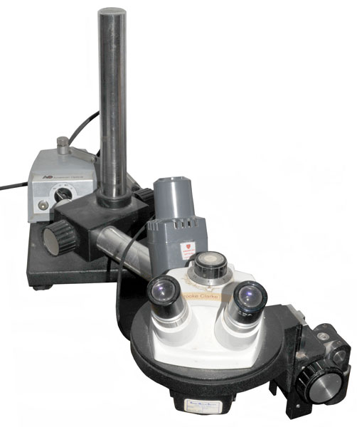
When I was working with microwave components (Radar Warning Receivers) where the modules made use of raw semiconductor dice we used Stereo Zoom 4 microscopes. I've seen a web page that said that these should be called macroscopes because the magnification is low. It turns out that your hand eye coordination gets a gain boost by the magnification of the microscope allowing you to do work down in the 1/1000 of an inch area that would be impossible if done using normal (good) eye sight.
I really like the swing arm type of stand on a heavy base for the stereo zoom which allows you to get it over what's being worked on. The classical microscope stand would be in the way. I'm using the classical light bulb and optical illuminator that sits in a holder that can be rotated around about 3/4 of a circle on the microscope. A ring light would be much better.
Although there is a zoom knob, it spends almost all it's time on 0.7X. Combined with the 10X eyepieces, the power is 7X. It's properly called a macro-scope rather than a micro-scope because of the low power.
Stereo vision is mandatory to have depth perception.
I've ordered from eBay "60LED Adjustable Ring Light Illuminator Lamp For STEREO ZOOM Microscope" which should work better than the existing lamp which often is not in the correct place.
Note: at the bottom of the macroscope there's a screw in ring that's 40mm OD, 35mm ID and has what might be 38mm x 1.0mm threads and no optics. This would be the place to mount the ring light.
60LED Adjustable Ring Light Illuminator purchased from eBay seller jimshop268. The old illuminator would cast shadows and to avoid that required rotating the support, but that often pulled the cord (it seems the supplied cord always seemed to short) sometimes unplugging the lamp. This ring light casts no shadows and is brighter and cooler than the old illuminator.
| I removed the nose piece from the
microscope to adjust the pinch screws and it shows up
in the photographs. Top 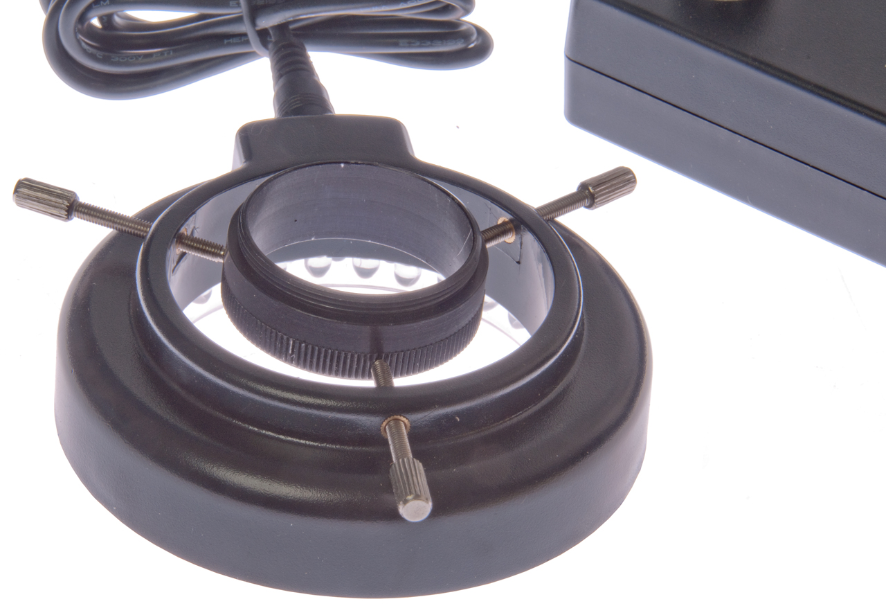 |
Bottom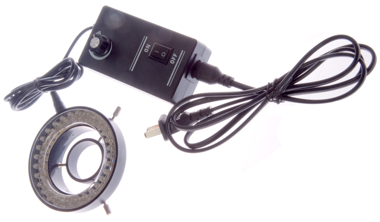 |
Top with LED ring light |
EEVblog #390 - Mantis Elite Microscope Review -
7123415 Optical instrument and optical element providing expanded exit pupil, Vision Engineering Limited, Filed: Mar 20, 2000, Pub: Oct 17, 2006, 359/569, 345/8, 359/566, 359/575, 359/573 - good for 8 hr/day use.
I found one on eBay, but it was freight shipping since the weight (without an objective lens) was 150 pounds.
Northridge Fix (Microscope1, Microscope2) uses an HDMI camera instead of a stereo zoom microscope for much more comfort. He has learned to work with the 2D image, i.e. he doesn't need the 3D stereo view. Microscope package $695. It's not clear if the 3" mounting ring adapter is included?
The HDMI camera may be the HAYEAR Model : HY-8050 Sku: 1901020654
180X Zoom lens Model HY-180XA, SKU: 0911170449
0.5X auxiliary lens Model : HY-05X SKU: 1801195342, 48mm mounting thread
EEVblog #1125 - Amazing $500 Soldering/Inspection Microscope!, 19:82 - Eakins auto focus C-mount camera with Sony IMX290 chip & 180X zoom lens. a better lens might be the 120X or get a 0.5X add on lens. A 24" HDMI monitor would be good.
Pitch
There are also metric pitch SMT packages, i.e. instead of 0.05" (1.27 mm) pitch a metric SMT would have 1.25 mm pitch (0.0492"). If you use these be sure to use metric board layout (or convert back to inches).
Soldering Methods
Commercial
Hobbyist SMD Soldering Methods
Solder Bridges
The first problem is that the soldering iron tip may be much wider than the width of a single lead (about 0.012 inches) and so solder gets on two or more leads causing a solder bridge. It may be that a liberal application of flux will reduce this tendency. Using a hot air rework tool is good in that there is no iron tip to smear the solder where it does not belong.SMD Lifting
The second problem is that the surface tension of the solder may be stronger than the weight of the SMD, in which case the SMD may lift up when the soldering iron is lifted. Some ways around this are:- Use tape to hold down the SMD (Spark Fun method) - I don't like tape because it's hard to adjust the part location
- Use Elmer's yellow quick dry wood glue to glue down the SMD (Electronic Goldmine method) - I've done this and it works. You need to wait 15 to 20 minutes for the glue to dry and rework is more difficult
- Use Tack n' Stick Reusable Adhesive (Black Box Camera
method) - Works with soldering iron, but not hot air.
Fine Point Hand Iron
Note that there are two factors relating to soldering iron and what they can solder. One is the power rating (Watts) of the iron and the other equally important is the heat capacity (pretty much relates to the weight of the tip) of the tip. Note that the WES50 is rated 60 Watts, but it can not solder wire terminals on 12 AWG wire because the wire acts as a heat sink and the small tip and not transfer enough power to melt solder. The Weller SP-40, rated at 40 Watts, can easily solder terminals to 12 AWG wire, but not so easily to 10 AWG where the 200 Watt iron can do that easily.
| Weller WES50 with ET-S fine tip (60
Watt rating) Used for electronics. 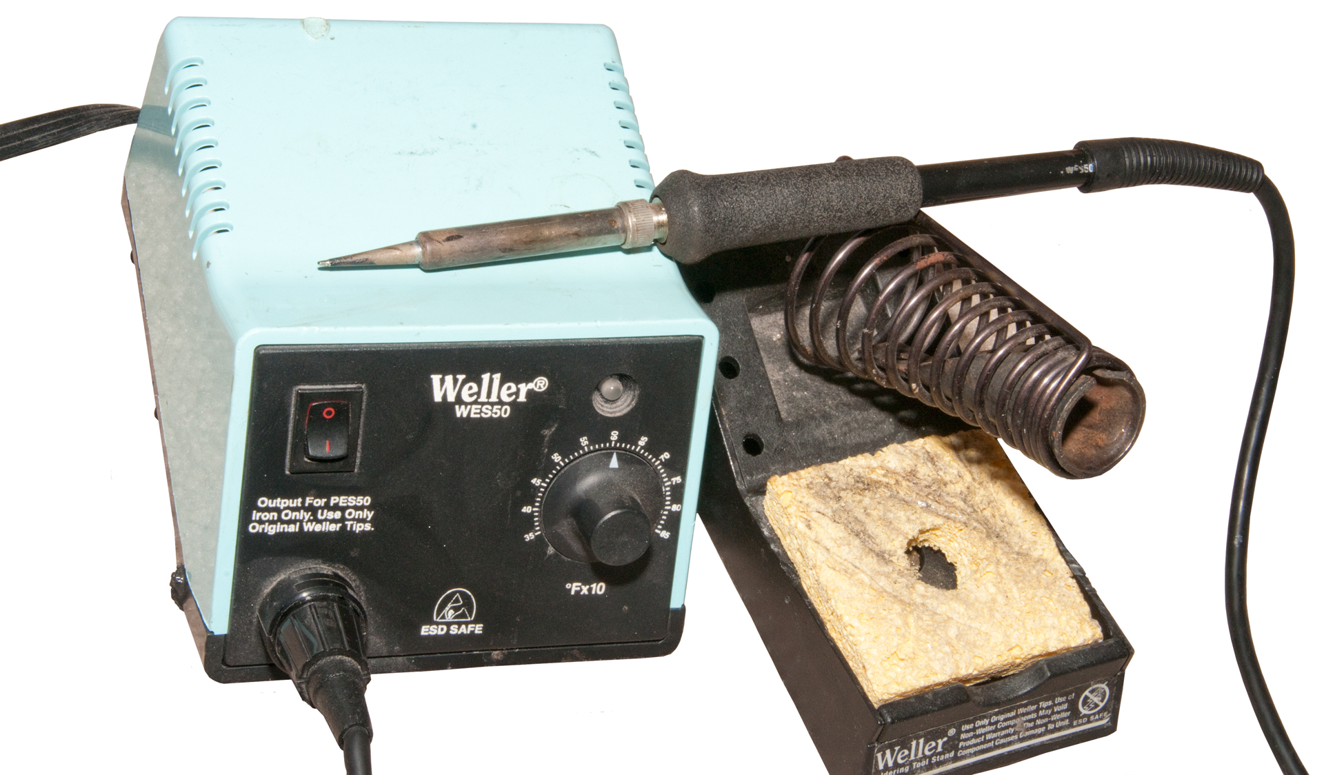 |
Example of SMT hand soldering. Battery Top Signal Generator |
| Weller SP-40 40 Watt iron not suitable
for SMT work. Used for soldering terminals to some wire when crimp is not used.  |
| Generic 200 Watt soldering iron totally
not suitable for SMT work. Used for large wire (>= 10 AWG) terminals, like EC5.  |
5 May 2006 - When using a Weller WES-50 soldering iron with the ET-S fine tip (this tip is maybe 10 times smaller than the stock tip) and Kester wire solder that's 0.015 diameter with 282 flux core I was easily able to hand solder the SOIC-28 package onto a professionally built PCB that included solder mask and silk screen layers. The board also has a thin lead tin solder coating on the pads. I think the four components that made this easy are :
(1) the stereo zoom microscope,
(2) the solder mask on the PCB,
(3) solder coating on the PCB
(4) solder coating on the IC leads. Prior to placing the SOIC the PCB pads were wetted with RMA liquid solder flux and the SOIC was held in place with Blu-Tak. This worked better than the hot air iron because there was much better control of the amount of solder. My solder paste dispensing method is at fault and if fixed I expect that SMT with the hot air tool will be a better method, but for now this is the best by far.
Note that just by applying the iron to a single lead solder reflow occurs, from both the lead and PCB. There is not enough solder to get good fillets, but enough to hold the part firmly allowing the Blu-Tak to be removed giving access to all the leads. Applied a very small amount of solder to the pad just in front of the lead foot and when it melted the solder ran under the lead resulting in a nice fillet. There was not a single case of solder bridging. Visual inspection easily showed leads without a fillet at the foot of the lead and they were easily fixed.
Note that the board being assembled only has a one SMD, the SOIC-28, all the other parts are conventional through hole mounted.
There's about 3.5" inches between the tip of the Weller WES-50 to the tip of the ET-S. This is a problem when working under magnification because the iron may be completely out of your field of view and that's when you're likely to move it into your skin (ask how I know this) Ouch.
I see that the Weller WSL Micro Soldering Station advertises having the shortest tip to grip distance. Tthe WMP iron used on this station has a tip to grip distance of 37 mm (1.5"). That's good but it really should be a shorter distance, more like 1/2". This may require forced air cooling or some other fancy method, but for using a soldering iron with a microscope the grip to tip distance should be very short.
Aug 2010 - I've used this method with great success for 1/2 and 1/4 pitch parts and don't see much need for the hot air system.
Toaster Oven
Electric Fry Pan
Plastic Welder
Modified
Solder Sucker into Hot Air Rework type tool
Commercial Hot Air Solder Reworking Tools
Quakko 850D Hot Air SMD Rework Station
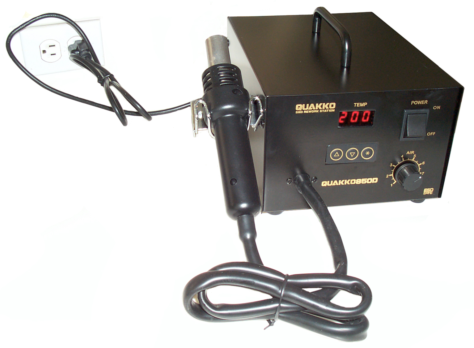 The Quakko
850D photo is with the unit right out of the box with no
nozzle installed. When the switch is turned ON, the
blower comes on and the temperature is regulated to the
default value of 200 deg C. Only a low humming noise
from the air pump. When the switch is turned OFF,
nothing appears to happen, while the blower continues until
the air temperature goes below 100 C. then the blower shuts
off. A very nice feature that will extend the life of
the heating element. My first get aquatinted uses for
the 850D will be trying to use it where normally a hand type
soldering iron would be used.
The Quakko
850D photo is with the unit right out of the box with no
nozzle installed. When the switch is turned ON, the
blower comes on and the temperature is regulated to the
default value of 200 deg C. Only a low humming noise
from the air pump. When the switch is turned OFF,
nothing appears to happen, while the blower continues until
the air temperature goes below 100 C. then the blower shuts
off. A very nice feature that will extend the life of
the heating element. My first get aquatinted uses for
the 850D will be trying to use it where normally a hand type
soldering iron would be used.Nozzles
The tip of my hot air gun is 21.6 mm O.D. and I understand there is a standard size for all hot air soldering guns. There are a few dozen different nozzles available. Some have just a round outlet tube for single point heating. One web page suggestgs that the single point tip hot air tool may replace the standard soldering iron because it works better. Other nozzles are matched to the SMD, such as for different sizes of: SO or SOIC (Small Outline Inline Circuit), QFP (Quad Flat Pack), PLCC (Plastic Leaded Chip Carrier), BGA, CSP (Ball Grid Array), or SOJ (Small Outline with "J" leads).This might be a rebranded Aoyue Hot Air Rework Station although they don't offer the 850D, just the 850 and 850A.
Or more likley a knockoff Hakko model 850D since the Hakko 850D is not obsolete, replaced by the FR-801, FR-802 or FR-803. These have a ball in tube air flow monitor and the two higher numbered versions have a key lock on the internal settings.
The manual says the main use of the 850D is for removing SMDs. But when used for soldering to watch for solder balls and bridges. The 850D can also be used for shirnk tubing.
There seems to be two styles of hot air irons. Those that have the air supplied by a diaphram pump in the main box and those that have a fan in the tool handle. I expect that the fan in the tool type are very similar to the Harbor Freight Heat Gun (see below) and will have a short fan motor life.
| Temp C |
Single hole nozzle |
Multi hole nozzle |
| <
350 |
1
to 5 |
4
to 7 |
| >
350 |
3
to 8 |
4 to 7 |
| <
450 |
4
- 8 |
4 to 7 |
Pre Heaters
Harbor Freight Heat Gun
 The $10 heat
gun (Harbor Freight Heat Gun 35776)
used mainly for shrink tubing has a 35 mm diameter where it's
accessory nozzles fit. But when you buy the $20 heat gun
in the kit (47269)
it comes with a reducing nozzle from 35 mm to 23 mm adapter
that's a little tight, but does accept the rework station
nozzles. The bad news is that without the adapter (just
the stock heat gun) it can not melt solder enough to ball up,
just turns dull gray color. With the adapter and nozzle
it will not melt solder at all. But there might be a
modification that would make the heat gun run hotter?
The $10 heat
gun (Harbor Freight Heat Gun 35776)
used mainly for shrink tubing has a 35 mm diameter where it's
accessory nozzles fit. But when you buy the $20 heat gun
in the kit (47269)
it comes with a reducing nozzle from 35 mm to 23 mm adapter
that's a little tight, but does accept the rework station
nozzles. The bad news is that without the adapter (just
the stock heat gun) it can not melt solder enough to ball up,
just turns dull gray color. With the adapter and nozzle
it will not melt solder at all. But there might be a
modification that would make the heat gun run hotter? But even if you could make it run hotter the time until the fan motor fails may be decreased from the stock 1 year to some much shorter time.
Solder Paste
 For a
first try I got Kester
R276SRSN63 The R276 is the no clean flux, SR is for
Syringe and SN63 is for old fashion Lead Tin. This is
a 35 gram (10 cc) size.
For a
first try I got Kester
R276SRSN63 The R276 is the no clean flux, SR is for
Syringe and SN63 is for old fashion Lead Tin. This is
a 35 gram (10 cc) size.The shelf life is 6 months from the date of manufacture when stored refrigerated between 0 to 10 deg C ( 32 to 50 deg F) and so needs to be shipped using an overnight service in a refrigerated box (the same styrofoam type box is used to ship cheese).
Paste is also available in a number of larger containers. But for small runs the problem is that the paste will exceed it's shelf life before it gets used, so the smallest possible container is desirable.
A problem with solder paste is that most distributors no longer carry it. Probably because of the short shelf life. They will supply case quantities drop shipped, but this is not practical for a small business. Techni-Tool seems to carry both and will sell individual tubes.
R276 No-Clean is TT No. 488SO540 and the R500 Water-Soluble is TT No. 488SO5603
The Mesh: -325/+500 means it's type 3 which is the stock solder power. Type 4 is a special order finer powder.
Aug 2010 - not needed for 1/2 pitch parts. Just use small diameter solder and a fine point iron.
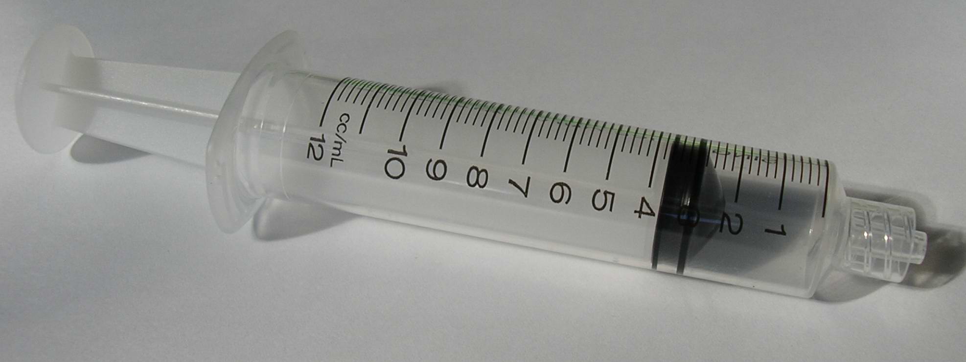
Luer Lock
Just as the SMT business borrowed the "tape" from the movie industry, they borrowed Syringes from the medical industry. Back in the 1950s medical syringes were made of glass and the needles were all metal. The syringe had a tapered outside diameter that attached to the needle. Doctors were supposed to use an auto-clave to sterilize them prior to the next use.Modern medical syringes are called "Luer lock" and are made out of plastic. They have a taper (maybe the same one as used in the 1950s?) and in addition there is a sleeve over the taper that has threads on the inside. The needle has either "ears" or a male thread. To attach the needle to the syringe you screw it on.
Plunger
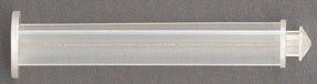 In addition to the
syringe you also need a plunger to push out the paste and a
needle to form it into a small diameter. Commercial
practice is to use a pneumatic actuator that will put out a
controlled burst making a controlled dot of paste and the
fancy ones have a pull back.
In addition to the
syringe you also need a plunger to push out the paste and a
needle to form it into a small diameter. Commercial
practice is to use a pneumatic actuator that will put out a
controlled burst making a controlled dot of paste and the
fancy ones have a pull back.Kester has sent a complementary plunger. I've seen on the web plungers with a bigger diameter head that rests in the palm of your hand. It would be easy to adapt a caulking gun to work the solder paste tube. Once installed the plunger may lock to the solder paste tube preventing reuse. The plunger dies not lock and is a nice fit in the tube.
28 April 2006 - I've had an adapter made that fits a standard caulking gun. It holds the syringe and when the disk shaped normal caulking gun plunger is removed the existing rod will fit the syringe. It is not needed with the huge 14 ga needle. Will see how it works with the Yellow finer ga needles. questionable if needed.
I have also seen kits that contain a plier type device designed to give more leverage and maybe some metering of the paste, but expensive.
Needle
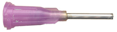 The
needle diameter should be between the lead width and 1/2 of
the lead width (from another web page, but see the calculation below). (This
recommendation may have been for chip resistors or
capacitors that were much larger than SOIC or finer pitch
ICs?) Run a line of solder paste along all the pads
(solder paste will be between pads). Place part paying
attention to orientation or polarity. For the SOIC-28
package where the lead is 0.008 inches wide this suggests a
needle I.D. of 0.004 to 0.008 inches. Note that the
smallest needles are 30 ga or 0.006. In addition the
solder paste uses different solder powder sizes and these
are rated for 22 ga (0.020 inches) for the solder paste I
have. So it looks like the smallest needle that can be
used with this paste (there are other pastes that use a
finer solder powder called Type 4 that may have been a
better choice) may put down too much solder.
The
needle diameter should be between the lead width and 1/2 of
the lead width (from another web page, but see the calculation below). (This
recommendation may have been for chip resistors or
capacitors that were much larger than SOIC or finer pitch
ICs?) Run a line of solder paste along all the pads
(solder paste will be between pads). Place part paying
attention to orientation or polarity. For the SOIC-28
package where the lead is 0.008 inches wide this suggests a
needle I.D. of 0.004 to 0.008 inches. Note that the
smallest needles are 30 ga or 0.006. In addition the
solder paste uses different solder powder sizes and these
are rated for 22 ga (0.020 inches) for the solder paste I
have. So it looks like the smallest needle that can be
used with this paste (there are other pastes that use a
finer solder powder called Type 4 that may have been a
better choice) may put down too much solder. In a commercial setting the needle is held vertically and a round "dot" of solder is applied. In this case the important thing is the volume of solder for each joint. For hand use the volume of solder for each joint also needs to be correct. I'm thinking of ways to get this right in a controlled manner.
One way may be to use a roller, like is used for inking a printing press. I've seen small rollers offered for this purpose. The roller is charged by rolling it on a flat surface then transferring the solder paste to a single row of pads.
The needles have arrived.
The needles have an ID range of 0.006 (30 ga) to 0.069 (14 ga) inches. But a given solder paste typically has a recommended minimum needle size.
The classical medical type needle (except no diagonal cutting edge, just blunt) take more pressure to get the solder out. Tapered needles are easier to use, but only come in 0.063 (14 ga) to 0.013 (24 ga). The 24 gauge may be just about right for an SOIC-28 package with 0.008 lead widths.
Kahnetics makes SMT type needles.
See Luer Lock above under Syringes for how the needle attaches to the syringe.
 30 May
2006 - while at the doctors office I got a B-D model 305155 needle
that's 22 ga by 1" long and a 25 ga by 5/8 long (B-D
5122). Both of these use the same Luer Lock system as
the needles sold by the SMT distys.
But they have sharp points! There may be a way to
grind off the point and also make the tube much shorter,
like 1/2" or less long. The shorter the tube the
easier it should be to push out the solder paste. So I
now have a selection of needles from Techni-Tool (20x0.5
yellow), and Kester
(16x0.5), a disty I won't mention (16x0.5 violet), and the
medical needles (22x1 gray and 25x0.625 lt blue). 25
ga looks very small, like no solder paste is going to go
through it.
30 May
2006 - while at the doctors office I got a B-D model 305155 needle
that's 22 ga by 1" long and a 25 ga by 5/8 long (B-D
5122). Both of these use the same Luer Lock system as
the needles sold by the SMT distys.
But they have sharp points! There may be a way to
grind off the point and also make the tube much shorter,
like 1/2" or less long. The shorter the tube the
easier it should be to push out the solder paste. So I
now have a selection of needles from Techni-Tool (20x0.5
yellow), and Kester
(16x0.5), a disty I won't mention (16x0.5 violet), and the
medical needles (22x1 gray and 25x0.625 lt blue). 25
ga looks very small, like no solder paste is going to go
through it.The medical needles have a safety shield over them so you won't get poked. It does not come off using just your hands. This idea is that when you screw the needle onto the syringe the safety shield is loosened and can then be safely removed.
Volume Calculation 24 May 2006
A first cut looks at two places that solder would be. All dimensions in mills (1/1000 inch) Package is SOIC-28.
1) an even layer on each PCB pad maybe 2 mills thick. The pads are 14 x 80 mills so that's 2,240 cubic mills.
2) a filet on the sides and both the end and the back of the SMD foot which is 8.5 mils wide and the length of the foot may be 65 mills for a total filet length of 150 mills (rounding up). The filet looks like what's left if you subtract a circle from a square and take 1/4 of that where the square is 0.0085 on a side. So the area of the filet is about 4 square mills for a filet volume of 600 cu mills.
Adding 2,240 and 600 gives 2,840 cu mills of solder for one lead.
Solder paste has about 87% solder by volume so the calculated solder volume needs to be increased to paste volume
2800 / 0.87 = 3,264 cu mils of solder paste.
Since the pitch (distance between lead centers) is 25 we can divide the volume by the pitch giving the area of a bead.
3264 / 25 = 131 sq mills, or the ID of a round needle would be SQRT(4*A/PI) = 13 mil ID or 25 ga, way too small for this paste.
So a 20 ga needle (min size for this paste) with an ID of 25 mills is about 4 times the volume required and a 14 ga needle (0.063 ID) with an area of 3,117 sq mils is 25 times too much solder!
Upper Bound
If too much solder was on each pad then there would be about a 1/2 cylinder on top of each pad. Since the pad is 14 x 80 the cylinder volume would be 80 * PI * 14 * 14 / 4 = 12315 cu mils and half a cylinder would be 6157 cu mils of solder or 6157/0.87 = 7078 cu mils of paste.
The paste bead area would be 7078 / 25 = 283 sq mils for a needle ID of SQRT(4*283/PI) = 19 mils or 22 ga. So it's clear that a 20 ga needle is way too big for laying down a cylinder that's as long as the distance between the end pads on each side.
This is consistent with the idea that the way needles are used commercially is to put down round "dots". The "dots" do not need to be inside the pads they just need to touch the pads so capillary action can suck the solder to the joint.
Plan
On the next try with the Yellow 20 ga needle maybe putting down a bead that is 1/4 the length of the side or about 14/4 = 3.5 pads long. Spread it out over the 14 pads. Then do the same for the other side.
Application & Use
 Afternoon of 4 May 2006 - needles
arrived. They are 16 ga which is way too big to just
put down a bead and melt it. The result is to solder
bridge all the leads into one blob.
Afternoon of 4 May 2006 - needles
arrived. They are 16 ga which is way too big to just
put down a bead and melt it. The result is to solder
bridge all the leads into one blob.To fix that just soak solder wick in RMA flux (probably the no clean and the water soluble flux would also work, it just has to be a liquid not a dry powder) and using a normal soldering iron wick off the excess solder. But now the part is not aligned with the pads. So using the hot air iron with no tip melt all the joints and move the chip from the pads. I then used Blu-Tak to hold the chip in place and with the small round tip on the air iron reflow the solder on most of the pins. But there were still some pins not soldered (can tell by poking them with a needle). To fixed those used Weller WES-50 soldering iron with the ET-S fine tip and Kester wire solder that's 0.015 diameter with 282 flux core.
The Blu-Tak leaves a gummy residue where it's been heated to solder melting point so there's still a procedure to be developed. It may be that just the normal soldering iron would work, will know more on the next one. The gumy residue makes for bad solder joints.
It's not necessary to try and apply the solder only to the pads, but instead it can be applied in a row covering all the adjacent pads and when it melts will move under the leads leaving a space between leads. This may be more true when there's a solder mask on the PCB, like in my case. The problem is geting too much solder paste.
One of the web pages on soldering SMDs says to heat the board from below, after the paste has been applied and the part installed, until the flux activates and the solder flows to the individual leads, then use a small pencil point of hot air to reflow the solder to get wicking on the sides of the leads (this done while the board is heated from below). Other web pages say the same thing but suggest using a hot plate or fry pan for the lower heat source. These ideas are probably necessary when working with Ball Grid Arrays or other packages that have zero tolerance for board warping, but for SOIC or other packages that are tolerant of board bending it's not necessary to heat the board from below.
Another possible reason for doing this would be the case where the board has a large difference in the total percent of copper on one side when compared to the other side, for example a microwave board where the back side is all copper and the top side has almost no copper. This will make the board bending worse, but still should be OK for leaded SMDs.
It looks like the default 850D temperature of 200 C is on the low end for Lead-Tin solders and the manual says to use 300 to 350 deg C.. The manual also says the air speed depends on both the type of nozzle and the temperature setting.
Solder Wick
Silk Screen
Printed Circuit Boards
- Simple board that just has the top copper layer with no features
- Solder-Mask over Bare Copper ( SMOBC) typically a green
color
- Plating over copper, might be conventional solder or for
RoHS, tin or silver plate (in all cases the traces are
metalic silver in color not Cu colored)
- Silk screen (typically white ink over solder mask)
Boards that have solder plated on the copper will need less solder to make a joint than will boards that do not have any solder. I'm thinking about how to calculate the amount of solder needed and convert that into a needle I.D.
It's more economical to have one board made with many circuits on the board and cut them apart yourself. It's only been since Feb 2010 that I've found the 12" Bench Top Hand Shear that will easily cut the 1/16" PCB material.
SMDs
Some of the packages have gull wing or "J" leads and so after being soldered there is some compliance between the part and the board, so if the board flexes there is strain relief (SOIC, SOT-23). But some of SMDs come in packages that have no compliance like the Ball Grid Array or Quad Flat pack (QFP). Working with the chip parts or parts with leads is much easier than working with the no compliance parts.
Tools
Magnifying Lamp with ring light (Harbor Freight model 31679 or model 34018 the later one looks like what I used to use.
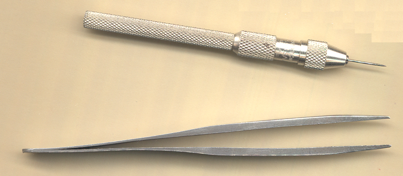
Pin Vise with sewing needle - good for moving small mechanical things and when a DMM probe is slid down the hollow handle makes an excellent electrical test probe. It will puncture conformal coating or sit on an IC lead where a normal probe tip is way too big.
Tweezers - Note these tweezers have very thick (stiff) legs, unlike 99.99% of the tweezers that have flexible legs. With these you can pickup a delicate part and if your grip changes pressure the legs do not deform. When your grip changes pressure when holding the flexible type tweezers the legs bend and can change from holding a part at the far corners to holding it at the near corners, and then the tweezers launch the part into the air never to be found again. They have been stamped 00c but I don't know where to get another pair. I've had these for maybe 40+ years. They're great for bending hookup wire for use in white plastic type proto boards and all kinds of other things that small pliers might be used for, yet they can do it to much smaller items. highly recommended.
Otto Frei - watch, clock & Jewerly supplies - Dumont Swiss Made Style OO Tweezers - Horotec Stainless Steel Antimagnetic #00 -
Panavise Jr. (Jameco 134439)- works well for small boards without bolting down, which allows it to be rotated. Also once a board has been clamped you can loosen the ball joint clamp and flip the board over. The more I use it the more I like it. No need to bolt it down, making it much easier to position under the Magnifying Lamp with ring light.
Exacto knife -
Blu-Tak - only for use with conventional soldering iron, not hot air iron
Solder wick - always use with flux pen
RMA flux pen - use with solder wick
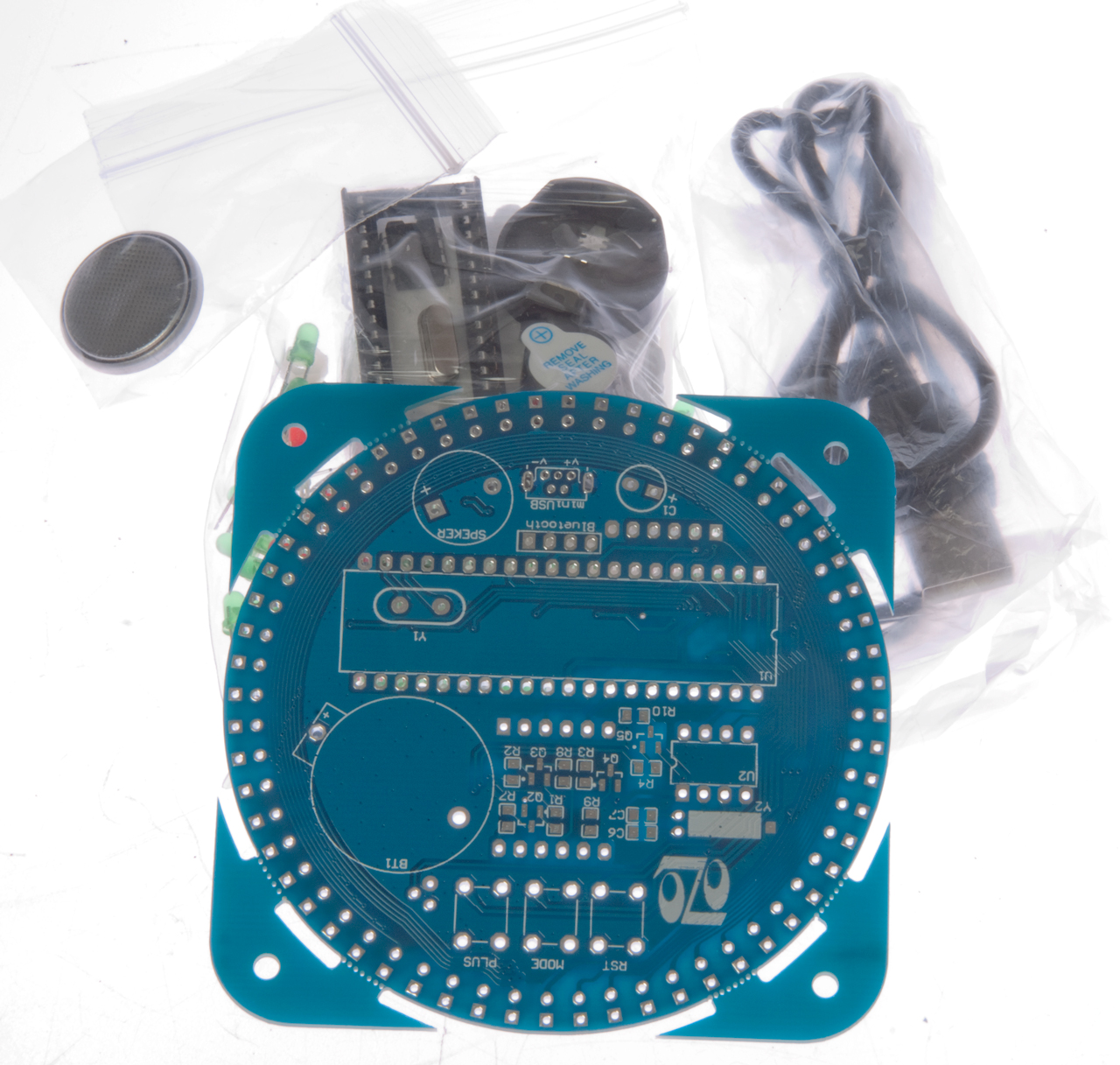
eBay Clock Kit
This LED clock kit uses a lot of surface mount parts, but only cost $8 including shipping from China. May 2015 I'm using it as a test case for SMT assembly.
Fig 1 Kit as received
Related Web Pages
12" Bench Top Shear - easily cuts 1/16" PCBs with one hand and not much force on lever (far better than the 8" mini shear break)
Hints and Tips (or What Goes Wrong) -
Electronic Construction Techniques -
Products in Development - this will vary depending on the date you are reading this.
Links
Introduction to Surface Mount Technology and Surface Mount Devices for the Small Manufacturer and Hobbyist: Prototype Manufacturing, Rework, and Repair Techniques -
Smart SMD Soldering - Using Blu-Tak (stationary store product for hanging paper on walls) as a chip holder to get hand soldering started. Staples calls this Tack n' Stick Reusable Adhesive Item 334690 Model 10448 - it's sort of like an oil based clay, but better.
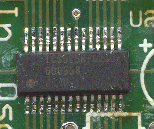
ICS 525 based Ham Radio Transmitter SOIC-28 fine pitch package with some soldering pointers for an iron.
Building with Surface Mount Technology (SMT) - Tinning -
A brief introduction to prototyping with Surface Mount Technology -
Using surface mount parts -
SMT assembly techniques -
'Have you seen my new soldering Iron?' - photos of using solder paste & toaster oven
Techni-Tool - carries solder paste in individual tubes and needles ($50 order min or $10 handling charge. There web based search engine does not find things that they have so either get the printed catalog or call them at (800) 832-9866 #4.
Making Prototype Printed Circuit Assemblies -
Spark Fun - How low can you go? Reflow Skillet!
Smart Tweezers - good review from user about $300
This is the [an error occurred while processing this directive] time this page has been accessed since since 18 April 2006.