Stellar Time Keeping
© Brooke Clarke 2006 - 2007
Earth Tides
Limit on Time Accuracy
Ideas
1. Averaging
2. GPS Meridian Crossings
3. Plate Solving
Background
Eyeball Daytime Star Viewing
Star Tracker Operation
Idea
Optical Tube Assembly
IR Pass Filter
Sky Measurements
Where to Look
Imager
Signal Processing - Timing
Camera Mount
Choosing Stars
Drift Scan
Photoelectric Photometer
Daytime
Stellar Imager
History
Patents
Links
Earth Tides (Wiki)
Just as the Sun and moon cause the ocean tides they also cause
the crust of the Earth to move up and down. This means
that the location of a telescope on a mountain of granite will
move up and down maybe a foot with the same timing to the local
tide gauge. It also means that the Earth's period will
change with the tides. There are Love Numbers (Wiki) that
describe how the Earth's crust responds to these tidal forces.
In the paper: Variations
in Rotation of the Earth, Results Obtained with the Dual-Rate
Moon Camera and the Photographic Zenith Tubes by Wm.
Markowitz, USNO in The Astronomical Journal Vol 62 No 1268, 1959
he says the variation in the Earth's period due to the tides is
on the order of plus and minus 30 milliseconds of time. It
was not until the availability of good quality quartz frequency
standards (Dye (Essen) Quartz-ring) that this type of
measurement could be made.
This is a large enough change that it can been seen by looking
at the stars, even though the day to day variation is too small,
see Visual real time limit below. But he used a PZT and/or
dual-rate
Visual Real Time Limit
Astronomical "seeing" limits what
can be done. The effect of seeing is similar to the star's
position changing. Seeing ranges from 0.5 arc seconds for an
excellent location to 2 arc seconds for most locations to 5 arc
seconds for poor city locations.
Star movement at zero degrees declination is 15 deg per hour or 1
arc second in 66 time milli seconds. At other declinations
the movement is slower.
So the best possible result is a timing accuracy of 33 milli
seconds to around 100 ms.
The following table shows the measured variation in the Earth's
rotation showing the daily change (
dEpsilon) in ms
(0.001") of time.
To have the same resolution as the ERSI table you need 100us time
resolution but the best seeing is 330 to1,000 worse that that.
Earth Rotation Service
Bulletin
B lists UT1R-UTC for each day. (2007)
Date
MJD x
y
UT1R-UTC UT1R-TAI dPsi dEpsilon
2007
"
"
s
s 0.001" 0.001"
(0h UTC)
JUL 8
54289 0.21518 0.39632 -0.161163 -33.161163 -62.2 -6.7
JUL 13 54294
0.21947 0.38319 -0.162176 -33.162176 -62.6 -7.1
JUL 18 54299
0.22589 0.37049 -0.162647 -33.162647 -62.9 -6.6
JUL 23 54304
0.22971 0.35703 -0.162754 -33.162754 -64.7 -6.4
JUL 28 54309
0.22925 0.34583 -0.162462 -33.162462 -65.3 -6.6
AUG 2
54314 0.22763 0.33130 -0.163459 -33.163459 -65.8 -6.2
AUG 7
54319 0.22785 0.31574 -0.164930 -33.164930 -66.7 -6.4
AUG 12 54324
0.22488 0.30185 -0.166586 -33.166586 -66.5 -6.6
AUG 17 54329
0.22113 0.28718 -0.168466 -33.168466 -67.4 -6.0
AUG 22 54334
0.21598 0.27252 -0.170614 -33.170614 -67.8 -6.4
AUG 27 54339
0.21213 0.25902 -0.173026 -33.173026 -67.8 -6.4
SEP 1
54344 0.20485 0.24686 -0.175802 -33.175802 -68.8 -6.3
SEP 6
54349 0.19825 0.23259 -0.178934 -33.178934 -68.4 -6.4
SEP 11 54354
0.19037 0.21835 -0.182414 -33.182414 -67.4 -5.7
SEP 16 54359
0.18113 0.20495 -0.186284 -33.186284 -68.4 -6.0
SEP 21 54364
0.17210 0.19350 -0.190507 -33.190507 -67.7 -6.5
SEP 26
54369 0.15845 0.18230 -0.195088 -33.195088 -67.7
-5.8
The change day to day is a few tesths of a ms so this
method may work as a way of measuring seeing, but will not measure
the earth's rotational period.
New Idea 1 Averaging
11 Apr 2009 - To get around the
"seeing' degradation of knowing exactly when a star crosses the
local meridian some form of averaging might be used. Some
possible ways:
- Use a number of photodiodes all in a line along the star
image path and determine the time when each was crossed by
fitting a curve to a plot of brightenss vs time and use all
the crossing times to arrive at the meridian crossing
time. The answer would be known not long after the last
photo diode was crossed.
- Use a star tracking telescope and record where it points
prior to, during and after a meridian crossing as a time
log. Fit a line to the plot and solve for the crossing
time.
- Use a number of telescopes, all seperated from each other by
more than one foot so that the "seeing" is independent at each
scope. This would allow measuring the "seeing" for each
pair of scopes so with three or more scopes the "seeing" of
each would be known. Then using the seeing as an inverse
weighting combine the meridian crossing times of each to get a
more accurate time.
- Use a lateral photo diode or X-Y CCD to plot the X-Y
position of the star as it crosses the meridian. This
would not involve any moving parts so is probably more
accurate than moving scope methods. The star image needs
to be less than 1/1000 of the resolution so that there are
many points so a normal TV grade CCD is not good enough.
New Idea 2 GPS Meridian Crossings
While looking into why the GPS
satellites are in the orbits that they are I discovered a couple
of the reasons are:
1) to bound the upper and lower limits of the Doppler shift.
Doppler shift was the basis of the Transit system and maintaining
Doppler shift for GPS was a prime consideration.
Geosynchronous satellites would have near zero Doppler and so were
not considered.
2) The GPS orbital period of 12 sidereal hours means that the
ground tracks of each satellite is the same day to day. If a
satellite wanders more than a degree off track it's steered back
on track. This I hadn't known before. Now there's a
strong analogy between GPS satellites and stars. That's to
say if you were to look at a vertical line on you South meridian
you would see the same GPS satellite cross at the same elevation
angle every 12.0 sidereal hours. If you knew when each
satellite crossed the meridian you could measure the Earth's
rotation period.
The time when any GPS satellite crosses your local meridian can be
calculated from the ephemeris data for that satellite.
The ephemeris data that's broadcast from each satellite is only so
good so if the broadcast data is used then there will be some
error. But the ground based reference stations monitor all
the satellites and have very accurate ephemeris data a day or two
later used for centimeter (2012 millimeter?) level land surveying.
Above is described how a 1 arc second angluar error in a star's
position causes a 11 milisecond time error a similar analysis can
be done for GPS positions.
For example a 1 cm error on the surface of the Earth with a radius
of 6,378.1370 km at the equator a distance of 1 cm corresponds to
an angle of 0.000090 deg or 0.32 arc seconds a little better than
the 1 arc second "seeing". So sub mm position accuracy is
needed to get the Earth's period error below a millisecond.
This probably can be done using GPS signals and maybe using
optical telescopes. The image of a GPS sat may be much more
stable than a star image because you could acually image the
satellite.
New Idea 3 Plate Solving (Dec 2016)
Time Nuts mailing list messages Opening Question:
out of curiosity, are there any amateur/semi-pro experiments that can measure the length of the solar or sidereal day to sub-millisecond resolution?
To reproduce data like this: https://upload.wikimedia.org/wikipedia/commons/5/5b/Deviation_of_day_length_from_SI_day.svg

Something in the sky that goes "ping" every day - detected with a pointing accuracy of < 1ms/24h or <0.01 arc-seconds (!?). Or perhaps two satellite-dishes pointed at the sun and noise-correlation/interferometry??

Anders
-----------------
from Chris A.
out of curiosity, are there any amateur/semi-pro experiments that can
measure the length of the solar or sidereal day to sub-millisecond
resolution?
Yes.  It is not hard at all to measure the Earth's rotational period, if all you needs is "sub millisecond"  It would get harder if you
cared about nanoseconds.

I worked on an amateur project with some others and while measuring the Earth was not the goal we had to know the Earth's rational period
to do the work.   The project was about stellar photometry.  But I leave that part out.....

Basically what we did was mount a camera made out of a small CCD sensor and a 135mm f/2.8 camera lens salvaged from  an old 35mm film camera.  The camera was fixed to the roof of my garage. (This was THE big cost saving feature:  The camera could not move.  The mount as fixed at one location in the sky forever, right at the equator)  I placed it in one end of a long wood crate and it looked up at the equator through a square hole on the upper end of the box.   The box provided some protection from the elements and provided a lot of light
shielding.

To measure Earth's rotation all you need to do in know exactly when you took an image and to have a GOOD catalog of star locations.  Let's say your image captures 200 stars.   They are rather blurry and each covers maybe 5 pixels but even so you compute the centroid of each "gaussian blob" and then do a least squares fit of all those centroids to the astrometric catalog.  The catalog is "good" to several milliacrseconds and with hundreds of centroids you can figure out were the camera was printed to a few  "MAS" (Milli Arc Seconds).  We
took many images every clear night for several years.    Hardware cost today is "not much" and you can use salvaged camera equipment  Almost all of the software is available for free. Certainly matching stares to catalog images is.  Yes the lens has geometric distortion and the CCD is likely not exactly 90 degrees to the optical axis but the software models this.  This is possible because millions of star
positions are known to insane levels of accuracy and if they appear in the "wrong" place in your image you can bet the cause is geometric distortion in your camera, especially after seeing the same error in hundreds of images.  We used narrow filters to limit the image to just one "color" so the chromatic aberration in the optics i not an issue, filters are cheap.

As part of our processing we time-tagged each image and also recored where the optical xis was pointed at.

So you'd need a small telescope or big camera lens and a camera that can be triggered by a computer and software.  Not really expensive.  I'd invest in the best used optics you can and get a monochrome camera.

Some people in the past century used transit telescopes to manually measure the time a star crossed a hairline in an eyepiece.  Then the next night to observe the same star again.  Now you know the length of the day (after you reduce the data)   Put you can measure a dozen stars every night and take an average.   In concept it is very simple.    But today we can measure a tens of thousands of stars per day from a suburban roof top.


Almost all other methods of measuring the Earth's rotation do not collect enough data.  You need tens or hundreds of thousands of data points. if you want to know the sidereal period to Time Nut standards.
Chris
----------------------

I think that you refer on prjects like Astrometry plate solving. I think one should got a reference to get a time reference instead of scope "pointing" reference, so, once one's got local coordinates in encoder positions, for example the values of the north pole with an alt/az mounting, can use a sub/arcsec plate solver to obtain good sidereal timing reference. using two encoders helps much.

The problem can be visibility of the reference points, however.
Best Regards,

Ilia
---------
Yes,  . . . basically correct.  But you save a ton of time and get better results if you simply bolt the telescope down to the Earth so that it can't move at all.   The aim point just needs to be "close" and then later you determine where it is aimed.    If you are only measuring period you don't need a surveyed location.   If measuring absolutely time you do.

Using a fixed mount is what makes this affordable by amateurs.  Epoxy the camera to a fixed masonry building.  This removes an unknown and dramatically simplifies the processing and also saves most of the cost witch is always the mechanical stuff.  One package of JB Weld epoxy replaces thousands of dollars of motors and encoders and precision gears.

With a fixed mount camera you have two kinds of "tine", that observed by the camera and a second from your GPSDO.  If they diverge then you deduce that it must be the Earth's rotation that changed.   But maybe you wonder of maybe the camera moved or some effect you forgot to remove.  So it is but to have some buddies running the same setup in different cities around the world and check that you all see the same results.   That is what we did.  It is FAR EASIER to do this kind of replication when the setup is very inexpensive.

Today you could build a camera for a LOT less then we did.  I'm thinking of a surplus used lens from a 35mm film camera.  A 250mm lens or so and a 3D printed plastic part that holds this to a cheap point and shoot camera.   We used epoxy to held the lens to the camera,  it meant you'd never be abler to take it apart again but it was going on a roof top, rain and all.
Background
I'd like to measure the Earth's
rotation using some type of optical system that uses either the
Sun or stars. In the book Splitting the Second by Tony
Jones it mentiones that the Photographic Zenith Tube was replaced
by the Danjon Astrolab. It works at night by allowing a
human observer to watch as stars cross a line of equal
altitude. It's very similar to the
Dent
Meridian Instrument opticallly. Also has not just one
time of concidence like the Dent but a number of them so that one
event can be measured a number of times, allowing for
averaging. By using some fixed evevation angle you can
measure many more stars than you can working straight up.
The good news about the Sun is that it's bright and so easy to
detect. The bad news is that the Earth's axis of rotation is
not at right angles to the plane of the Earth's orbit around the
Sun. Hence the elevation of the Sun is always changing and
over a year's time this amounts to a change of about 47 degrees,
so a fixed telescope
can
not be used. But stars always show up at the same
elevation for each meridian crossing allowing for a fixed scope.
Years ago I looked into doing this using a rotating mirror turning
on a shaft that was from a hard drive spindle, since at the time
that was the lowest run out bearing you could get. But I now
think that looking at stars that are within say 5 degrees of the
zenith could be done using a fixed scope and a mask with either
radial or circular slits that were about 1 star image wide.
It may be possible to see the brighter stars during the daytime if
the scope objective diameter is large enough and maybe with a blue
cut filter.
8 Aug 2007 - Although seeing stars in the daytime is a bonus, just
using a fixed scope pointing up to measure night time meridian
crossings of stars would be all that's needed. It may be
that a low light level security CCTV camera is adaquate. I'm
looking at the
PC164
now.
If mounted to a concrete pier looking straight up (as determined
by a plumb line) even if there was some misalignment, if the scope
stayed pointed in the same place the day to day timing would be
accurate.
Note that navigation systems and timing systems are closely
related. A navigation system can be used where the location
is the known and time is the unknown.
This is consistent with the performance of the
MD1 and newer
astro
compasses.
There are some U.S. patents on instruments that do this.
Eyeball Daytime Star Viewing
I have read about this happening
in some settings.
- Land surveyor's taking star shots to determine
position. Since they know roughly where they are the
transit can be setup and the scope aimed where the star
should be while the sun's up. Sometimes they can see a
star in the daytime.
- Men working deep underground in a mine look up a vertical
shaft and see a star.
- An astronomer looking through a telescope mounted on a
pier can point to and see some stars when using high power
eyepieces.
I think daytime star viewing is not something someone is likely to
stumble on. The three examples above probably have a common
theme. In order to see a star in the daytime with your eye
the right combination of factors needs to be present.
Light Gathering
One has to do with light gathering. The larger the area used
to gather the light the more sensitive is the result. For
example at dusk or dawn when it's too dark to see with your eyes
alone you can see quite well using binoculars that have an exit
pupil diameter of about 7 mm, i.e. matched to your dark adapted
eye. The exit pupil is the objective diameter divided by the
power, so for example a 7x50 binocular has an exit pupil diameter
of 50 mm / 7x = 7.1 mm.
If someone is in bright sunlight their iris closes down a a few mm
diameter so they are not in a good spot to look for weak
lights. But if in a forest with deep shade, inside a
building with a small opening to the sky or underground in a deep
mine your pupil is more likely to be dilated.
If for example a telescope or binoculars were fitted with a blue
block filter that did make a number of stars brighter than the
background you still could not see then if you were outdoors
on a bright sunny day. An extreme example would be
binoculars fitted with a pair of Hoya O-58 that cuts slightly more
than half the spectrum completely. The sky may appear black
to an eye that's out in bright sunlight. The only way for
this to work is from a dark daytime location or by using something
like a gas mask to block the daylight and allow your eyes to dark
adapt.
Magnification
Magnification has the effect of making a star (point source of
light) appear brighter while making the background (diffuse or
extended source of light) appear dimmer. The problem is that
at high magnification the field of view gets narrower and holding
steady is harder as is pointing to where a star is located.
Example: I've been bugging my neighbor Paul about daytime
star watching, and he recently took a photo of
comet McNaught taken at
noon. He said it was difficult to focus because of the
brightness.
Star Tracker Operation
The literature on star trackers
makes it clear that it is possible to track a bright (Navigation)
star in the daytime.
Many of these systems use a reticule (
episcotister)
or chopper in front of a Photo Multiplier Tube (PMT), or in newer
instruments in front of a silicon diode. The reticule can be
used in two ways, in one it's just a mask to gate the star light
and in the other it's a chopper to convert the light into pulses
that can be AC amplifier and synchronously detected. When
it's just a mask the slit width is a little wider than needed for
just a star. This does two things, one: it makes a plot of
brightness vs. time have a flat top like a pulse and two: if a
planet passes through the slit it makes a different shaped curve
with a pointed top since the slit width is narrower than the
angular diameter of most things like the moon or planets.
If the area of the light sensitive element is much larger than a
star image, as is typical of all these systems, then there will be
some background noise caused by the area that is not receiving the
starlight. This results in a lower signal to noise ratio.
Idea
Optical Tube Assembly (OTA)
Stable Focus
For unattended operation the focus needs to be stable. I
doubt a amateur telescope can ever hold focus over the normal day
to night temperature range encountered here in Northern
California, let alone somewhere else where the temperature has
much wider fluctuations. I'm convinced that it's not only
possible but not that difficult to design the tube assembly so
that the focus is independent of temperature to a small part of
the deepth of focus.
No mount is needed to the OTA can be mounted on a pier pointing
near straight up. This would be away from the house and
other man made areas, i.e. as far from both the house, driveway
and road as possible while still having some narrow view of the
sky.
Focal Length
The focal length of the lens
determines the scale factor. The arc seconds of coverage
for a pixel is given by:
arc"/pixel = 206 * (pixel size microns) / (focal len mm)
-or-
FLmm = 206 * (pixel size microns) /(arc"/pix)
When the seening is excellent you might have 0.5 arcsecond per
pixel conditions, so:
FL = 206 * 10 / 0.5 = 4120 mm or 4 meters for a 10 micron pixel
camera.
Focus Visible and Near Infrared
Silicon sensors "see" longer wavelengths than eyes. It's
very difficult to design a lens that can focus the different
wavelengths of visible light at the same place and nearly
impossible to do it for visible and near IR light. The
answer is to use an all reflecting optical system. Mirrors
do not have this problem.
Note that most amateur telescopes, like the SCT or "modified" RC
use a glass corrector plate that acts as a lens and so are not all
reflecting designs.
Primary Diameter and f-ratio
I've recently learned that the daytime sky is like an extended
object in that the lower the f-ratio the more of the daytime sky
background gets recorded in the camera. But star images are
point sources and the f-ratio does not effect their
exposure. So high f-ratio optical systems should be better
for daytime star watching. The other effect is that the
f-ratio is almost equal to the star image size in microns.
So the f-ratio should not be too different from the pixel size of
the camera. Larger diameter primary optics gather light
proportional to their unobstructed area, so larger is better, but
also costs more.
----------- Notes -----------
Newtonian telescope (or other all reflecting design so it works
well at near IR) mounted to concrete pillar. Carbon fiber
tube to help stabilize the focal length.
Mirror coatings may need to be customized for near IR reflection.
Scope City -
Newtonian OTAs
- 6"-f6, 10"-f5, 12.5"-f5, 16"-f5, 6"-f8, 8"-f6 all fiberglass
tubes
Vixen
R200SS 8"-f4 Newtonian OTA - not info on tube material
Meade -
truss-dobs
- 8"-f6, 10"-f5, 12"-f5
Telescopes.com - Discovery
series Truss Dobs -12.5"-f5, 15"-f4.2-f5, 17.5"-F, 24"-f5 - Truss
or tube material not specified
JMI - 12.5"-f4.5
there are a number of carbon fiber truss dobs on the market.
5 April 2007 - Orion has the
StarBlast
4.5" f4 dob scope for under $200. It's getting good reviews
mainly becuse of it good performance but for viewing and (in my
opinion more important) imaging with silicon sensors. This
would make a great OTA for stellar timekeeping since it's the
lowest f number I've seen on an off the shelf Newtonian
scope. The lower the F number the more curvature there is
and the harder it is to figure the mirror. The OTA uses a
metal tube. 114 mm dia x 450 mm FL (FL is 17.7" so tube
needs to be maybe 2 feet long to hold camera at prime focus)
14 April 2007 - Orion now is offering just a modified
StarBlast
OTA that good for use with CCD cameras. The secondary
mirror is larger and they've allowed for more infocus.
Sticker price $140 +s/h + rings
7 May 2007 - One test report says the plastic focusing housing is
very flimsy, not suitable for some TV cameras. Also if a TV
camera is mounted at prime focus it will be out of the top end of
the tube. So if possible the best thing would be to get the
4.5" f4 mirror and build it into a custom OTA with a longer
tube. I've asked Orion about getting the mirror. ans. no
only scope.
28 May 2007 -
Teleskop-Service
has a nice
f4
200mm Newtonian OTA for 500 euros. out of stock on the GEO
200 mm f4 (May '07)
31 May 2007 - OTA needs to keep imaging chip at the primary mirror
focus. The key specification may be the stability of the
support structure. Quartz rods or tubes may be an extreamly
high stability material that could be used in a truss type
structure.
GM Associates, Oakland, CA -
Quartz Scientific,
Fairport Harbor, Ohio - Rods: 2 to 13 mm dia, Tubes: about
150 sizes from 1x2 mm to 105x110 mm (4' lengths under 60 mm OD)
Newt
Software - free to download runs on most flavors of WIndows
Newtonian
Telescope Design Planner - IE and Netscape versions, for use
with cameras provides % illumination vs. sensor size
Yazoo Mills -
mailing
tubes -
ProtoStar -
Black Light
Telescope Tubes with black flocking made from
Phenolic-impregnated kraft paper
Hastings Pipe Co.
- sells Aluminum tubing cut to order for telescope OTAs.
Depth of Focus
The Airy disk diameter is 2
.44
x 0
.00065mm
x
f so for the StarBlast f 4 mirror d = 2.6 um at the green peak of
659 nm. and 4 um at 1,000 nm near IR. So the f # = Airy disk
diameter in microns (um) when IR light is involved.
The Depth of Focus =
2 x f x d = 2 * 4 * 4 um = 32 um or
0.00125" or just over 1 mil. The focusing method needs to
be able to position the imaging chip in increments much smaller
than 1 mil. The change in tube length over temperature
also needs to be will under 1 mil to avoid temperature
defocusing.
Thermal Coefficient of Tube
Aluminum has abut 12.3 "/"/F*E-6. The F.L. of the StarBlast
mirror is 450 mm or about 17". For a temperature range of
+70 to +40 deg F or
30 deg F change * 12.3E-6 * 17 = 0.0065 or 6.5 mils, way too
much for a 1 mil depth of focus.
Thermal Compensated Tube
Pendulum clocks change rate with tempereature becuase the pendulum
rod changes length. But this can be conpensated by using two
metals with different expansion coefficients such as steel and
zinc. John Harrison did this long ago. If the two
metals were just connected in a series straight line then there's
no compensation. An example of a compensating connection
would be to have a steel tube longer than needed at the open end a
smaller diameter zinc tube is connected at the top end to the
steel tube. The camera is mounted on the zinc tube down some
distance from the end. How far down depends on the relative
coefficients of expansion. If the coefficeients were the
same the camera would need to be mounted inside the mirror.
The larger the difference in expansion coefficients the less
length is needed to get the compensation. Patent class 359
optical systems/820 Lens.with support..lens mounts...with
temperature compensation. 359/820
1325936 Apparatus for Rendering the True or Apparent Focal Length
of Objectives Independent of Changes of Temperature, 1911, 359/820
; 219/121.6 compensates for both the lens mount and optical
changes in the lens.
Coefficient of Theremal Expansion
Metal
|
in/in.oF
x 10-6 |
| Aluminum |
12.3 |
| Brass |
10.4 |
| Iron,
forged |
6.3 |
| Phenolic-impregnated kraft
paper |
8
|
| PVC
thermoplastic |
29 |
Delrin
|
6.8
|
| Quartz,
fused |
0.33 |
| Steel |
7.3 |
| Steel
Stainless Austenitic (304) |
9.6 |
| Steel
Stainless Ferritic (410) |
5.5 |
| Zinc |
16.5 |
An aluminum tube 18" long would expand 18 * 12.3 *(bunch of stuff)
and would be compensated by a length of PVC that was (18" *
12.3)/29 long or about 7.6" long.
Concern about Camera inside Tube because of heat waves This was
brought up, but if a muffin fan is installed to blow outside air
past the primary mirror and out the top of the tube as is the
common practice for cooling off the mirror, then the heat gets
blown away. Seperating active voltage regulating circuits
from the camera and placing them nearby, but outside the tube
might also help.
Image size
Practical
Calculations for the Newtonian Secondary Mirror -
CFF = 0.000433(f)
3 and since the f# varies from maybe 3
to 12 the
Coma
Free
Field will vary from 0.011
inches to 0.748"
I = arctan (ID / FL) for example a 10"-f6 scope will have a CFF of
0.094 (just under 1/10") and if the CCD chip will hold a 0.5 inch
image (I.D.) then the angular field (I) will be ATN(0.5"/60") =
0.477454 degrees or 28.64 minutes. But the Coma Free Field
of view will be only ATN(0.094/60) or 0.08976 deg or 5.38 minutes
of arc.
For the StarBlast f4 mirror CFF = 0.0277" or about 8% of the 1/3"
CCD in a PC164 camera.
Working backwards to get a 1/3" CFF the f# needs to be about 9.1.
That may be a better match to the pixel size and would be better
for daytime star viewing. But makes for a longer tube, i.e.
a 4" diameter mirror will focus at 36" or about twice as long as
the f4 tube. But still within the size range that's easy to
ship or move. Also flatter mirrors are easier to find/make.
Discovery Telescopes
-
makes
6" f8 mirror $189
Newtonian Telescope Design Planner - an on line calculator
A
calculation of Airy disks for various telescopes by David
Whysong
C-Mount Lens
The thread is 1.0" x 32tpi.
The Cine mount expects the flange face to focal plane distance to
be 17.5mm. So a C-mount lens works on a C-mount camera.
If C-mount lens is going to be used with a CS-mount camera
an adapter ring 5 mm thick needs to be inserted. This means
that almost all new cameras use CS mounts so they can be used with
either type of lens and are typically shipped with the adapter
ring installed.
CS (C-Short) mounting is a newer standard.
The CS mount uses the same thread but the back lens flange to
focal plane distance is 12.5mm. A CS lens can only be used
on a CS camera mount, not a C mount.
The CCD or CMOS imaging chips that are typically in CS mount TV
cameras are typically 1/4, 1/3 or 1/2" nominal sizes.
IR pass Filter
My thought is that adding a filter
that cuts blue light (a red filter) will increase the contrast of
a star. As the wavelength of the cut gets longer more blue
light is cut but also there's less total light. So there's a
sweet spot where the contrast is the highest. A shorter
wavelength filter lets in more blue light lowering contrast.
Any longer wavelength filter cuts more star light lowering
contrast.
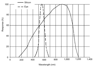
Visible light
is in the 400 to 700 nm range and silicon chips can see in the 200
to 1200 nm range. So a silicon chip will have more contrast
than an eye since it can see IR light from the star. The
quantum efficiency of a Silicon sensor is very high. Much
better than camera film or the eye. Blue is around 400 nm
and is the predominant sky color.
So the chart to the left may be misleading in that both the eye an
silicon sensor have both been normalized to 100 %. It would
be more meaningful so show them in terms of
star
magnitude numbers. But that's tricky because you need
to add an optical system in front of the sensor to have equivalent
systems.
------------- Notes -----------
Edmund Optics -
Hoya R-72 - passes some red and IR, or Hoya RM-90 passes only IR, not
visible red. The IR series filters may not be the best
choice to minimize the blue sky background and get the highest
contrast on a silicon sensor. The O-58 (Orange
580 nm) Sharp Cut Filter has less than 0.001% transmission at
the 550 nm peak for human visible light yet passes 590 through
2,400 nm. This may be a better choice.
Hoya
Optics - only sells polished 50 x 50 x 2.5 mm or 165
x 165 x 2.5 mm or unpolished 165 x 165 x 4-5 mm filters.
The
CM500
is the filter used in front of a silicon sensor to give it human
eye color balance. At the H-alpha wavelength of 656.281 nm
this filter has a transmission factor of about 0.14. A
silicon sensor is about 7.4 times more sensitive than the eye at
H-alpha.
The "
Balloon-borne
Large-Aperture Submillimeter Telescope” (BLAST)
"
BLAST
Autonomous Daytime Star Cameras"
"The cameras are capable of
providing a reconstructed pointing solution with an absolute
accuracy < 5″. They are sensitive to stars down to
magnitudes ~ 9 in daytime float conditions. Each camera
combines a 1 megapixel CCD with a 200 mm f/2 lens to image a 2º
× 2.5º field of the sky."
"Though both star cameras are nearly identical, they use
different CCD cameras. The first unit (ISC) uses the
QImaging PMI 1401 and the
second unit (OSC) uses the QImaging
Retiga
EXi. The specifications of these two CCD cameras are
listed in Table 1. The PMI 1401 has a deeper pixel
well. It saturates at 45,000 e- while the Retiga saturates
at only 18,000 e-. This enables the ISC to integrate
longer before saturation, and therefore detect stars in brighter
sky conditions. However, the Retiga Exi has more bits/e-,
therefore the OSC is more sensitive in dimmer conditions.
Both cameras are high resolution, with 10
6 pixels
measuring ~ 7 µm × 7 µm. Combined with the lens optics,
the small pixel size facilitates a precise pointing solution,
and reduces the background signal due to sky brightness in
individual pixels. Both CCDs have a peak quantum
efficiency of ~ 65 % at 600 nm, with maximum
spectral response from 400 nm – 850 nm. "
SBIG - Red
and Infrared Sensitivity - side by side comparisons of
what a silicon sensor sees in the near IR
DSS-7 is a prism type spectrometer
and SBIG has done some looking at the mid day sky and Alan was
kind enough to send me a plot. The sky has a radiance of
about 3E-7*W2 - 0.0052*W + 24.6 mW/cm2/micron/steradian.
So at 4000 ang (blue) it's about 8 and at 8000 angstroms
(near IR) it's about 1. A straight line almost fits but
the parabolic fit has R2 = 0.98
Alan mentioned that the problem is saturating the pixel even
after sever IR filtering (like 720 nm or longer) to the point
that a neutral density filter is needed. Also note the sky
background is an extended object so the fast f number has the
effect of giving good exposure to the sky background. So
for daytime viewing a high f number would be better. But
that means using a CCD with large pixels which gets very
expensive.
Radiance
and Transmission Models - but called "IR clutter
assessment", not visible light? - software for sky brightness
& transmission
Spectral
Sciences, Inc. - computer code for atmosphere
reflection and transmission -
5884226
System and method for modeling moderate resolution atmospheric
propagation,
702/3
702/3 is Data Processing: Measuring, Calibrating, or
Testing/Measurement System in a Specific Environment.Earth
Science..Weather
Two of the inputs to the program are the temperature and
atmospheric pressure.
Sky Measurements
Things that can be measured to learn
about the sky background.
Background Brightness
Astronomers can measure how dark
the night sky is by using the
Sky Quality
Meter. This meter is designed for visual observing,
i.e. the TAOS TSL237 light to frequency converter is filtered
(Hoya CM-500) so that the spectral response matches the
eye. If the filter was removed or a
similar
device was made without a filter, then you would have a
way to measure the background brightness for silicon sensors.
The field of view is a cone with a half angle of 40 degrees.
Seeing
Seeing (
Wiki)
has to do with how stable the column of air is above the
telescope.
Seeing
Monitor at SBIG. The
All Sky Camera
is very similar, only a different lens is used and the related
software is different.
One of these may make an excellent base for Stellar Time
Keeping.
The SBIG
STV
manual explained one way to make the measurement called
Differential Image Motion Monitor. A mask is placed on the
front of the telescope with two circular openings each a couple
of inches in diameter and with their outer edges on the outer
diameter of the scope. So, for example on a 10" scope the
center to center distance of the two openings would be 8".
With the mount tracking a bright star near the zenith the focus
is moved away from good focus a little to get two circular
images. The mask is rotated so that the the two images are
along a horizontal scan line. This allows the electronics
in the STV to measure the distance between the two images using
a very short shutter time (10 ms) hence the need for a bright
star. In perfect seeing this angular separation would
remain constant, but with degraded seeing the separation
varies. The FWHM is used to determine the seeing.
Note that for a non adaptive optics scope, i.e. virtually all
amateur scopes, there is no increase in resolution for diameters
above about 8" due to the limitation of seeing. Bigger
scopes can see fainter stars, but the spatial resolution is
limited by seeing.
Long IR Temperature (Clouds)
The temperature of the overhead
sky measured in the 10 to 20 micron range is a good indication
of the cloud cover. When the sky is clear (day or night)
the temperature reads at the limit of the sensor. In my
case that's about -11 deg F. But when there are clouds
it's more like +43 F. So this is a very good
cloud sensor.
Where to Look
Straight Up
This was my first thought.
The advantages are:
1) you can get very close using conventional plumb and leveling
methods. The mount is a concrete pier with the scope in a
fixed mount on the side.
2) the thickness of the atmosphere is at a minimum, thus
hopefully providing better seeing.
Other Places to Point Scope
To see stars in the daytime the
scattered light needs to be minimized.
1) Rayleigh Scattering is what
causes the daytime sky to appear blue. The molecules are
much shorter than the visible light wavelengths that bounce off
them. The "antenna pattern" for this scattering directs
the most light back toward the Sun and away from the Sun.
The minimum scattering would be with the scope pointing at 90
degrees from the Sun's position, i. e. 90 degrees declination,
or at the North Celestial pole.
2) Mie Scattering is what causes white light to be reflected
from particles that are bigger than the wavelengths of light
that bounce of them. The "antenna pattern" for this
scattering has a major lobe pointing away from the Sun and
minimum side lobes in all other directions. So to measure
large particles in the atmosphere you want to point a scope so
that you're looking very close to, but NOT into the sun, and
measure the sky brightness. To minimize Mie scattering
point to 90 degrees declination.
So, pointing to the North Celestial Pole (90 deg dec) will
minimize the scattered light in the daytime, but has the huge
disadvantage of not having any star transits to look at.
So 90 degrees declination is not a good choice. Zero
declination has the fastest star transits but will include the
Sun on some days and also maximizes the Mie
scattering and Rayleigh scattering.
So straight up, I'm at 39N Lat, which would be 51 deg dec. may
be close to optimum. But moving more toward 90 dec may
offer an improvement in contrast. Also it may be needed to
intercept bright navigation stars.
So the scope mount should be designed to allow tilting the scope
where the arc of movement goes through the North Celestial Pole,
i.e. is a Meridian Instrument.
The
Dent Instrument is a meridian
instrument and could be used with a small telescope. It
uses the congruence of two images to indicate meridian
passage. Also called the Prismatic Astrolabe as described
in
Plane and Geodetic
Surveying.
The
Danjon
Astrolabe which is intended for visual star meridian
crossings at user setable declinations for meridian crossing
timing, but is limited by human reaction time.
Imager
There are a number of things that
might be used as the image sensor.
Single Photo Diode
Has the big advantage of
simplicity. But has disadvantages, the main one is pixel
size is huge. It would require a very high f-ratio
telescope to match the star image size to the pixel size.
If the image size is considerable smaller than the chip then not
only will there be more noise but the timing of the star
meridian crossing gets to be more difficult.
CCD Camera
These have pixel sizes that are a
good match to affordable telescopes. Come in two
versions. One designed for long exposure astronomical
imaging and the other essentially TV cameras. The low
light security type cameras can see stars at normal TV frame
rates and have reasonable timing capability when used as a non
integrating TV camera. The astronomical CCD cameras use
much higher quality imaging chips and can see much higher mag
(dimmer) stars. But could only be used if they can be
shuttered or run fast.
The low cost security cameras, like the PC164 have the audo gain
control problem, but that can be modified.
------------- Notes -------------
The type of TV camera used for star
occultation timing, not the integrating type.
My
PC164C web page.
Super Circuits -
PC164C-EX
- does it have built-in IR cut filter? Ans: No, it's IR capable as
is
Notes(0)
on PC164C and 1004X CCD Low Light camera's - The PC164C is
more sensitive than the PC164-EX
The
Ideal Occultation Telescope - mounts TV camera at prime
focus eliminating the secondary mirror.
Video
Astronomy - First experiences with a PC164 camera - photos
of a Gain Modified camera
The
PC180XS
uses the same Sony chip as the PC164C and has a light blocking
area of 1 sq inch where the stock PC164C blocks about 1.5 sq
in. If the aluminum case is turned down to 1.25" diameter
the area would be 1.22 sq inches.
A purpose made camera using either of the Sony chips would have a
much smaller light blocking area. The chip has an area of
about 0.2 sq in.
This would be a long skinny PCB with the chip mounted at 90 deg on
the end. One way to accomplish that would be to use two PCBs
where the spacing was such that the distance across both boards
was 11.4 mm (0.449") then 8 of the chips leads could be soldered
the top board and the other 8 leads to the bottom board.
For astronomical use the PC-164 is typically modified by adding a
manual gain control. This way the stock Automatic Gain
Control will not try to make the image average to gray. For
better timing it would also be good if instead of a free running
oscillator for the syncronization pulse timeing the camera ran
from an external frequency standard.
Pixel size
and plate scale calculator by Stan Moore
PC164 Major Chips:
Guidance of
Sony semiconductor Datasheet -
CCD
Image Sensor(ICX) -
CCD
Camera System(CXA, CXD) -
Video(CXA,CXD)
Sony
CCD Image Chips -
ICX254AL
- 1/3" EIA HAD EXview (replaces ICX054) 510 x 492 pixels 9.6 x 7.5
um (12 um pixel diag)
IC258AL - 1/3" - P164C-EX not as sensitive as plain version.
Sony
CCD Camera System Chips -
CXD2463R
- Timing Controller for CCD Camera
CXA1310AQ
- Single Chip Processing for CCD Monochrome Camera
(
CXD1267AN
? in CCD data sheet) - CCD Vertical Clock Driver
The ICX285AL still camera chip may be a better choice since it
have more pixels (1392 x 1040) that are smaller
(6.45x6.45um). Note most Newtonian scopes have f numbers
around 5 so this is a very good fit for pixel size. BUT the
near IR is not as good as the ICX254 and the readout timing is a
little slower (15f/s instead of 30 f/s).
A custom hardware video processor could be made that would time
stamp star crossings. Probably the camera would be rotated
so that stars moved either along or at right angles to the scan
lines.
Signal Processing - Timing
By using a sync separator IC even
and odd fields can be identified as well as vertical and
horizontal sync pulses. At the end of each horizontal line a
peak detector is read and zeroed. This is no problem for a
micro controller in terms of speed. If both a peak and a
valley detector looked at each line then (peak-valley) is how
bright an object is. If the camera is rotated so that stars
move across (not along) scan lines Then a single star can be
tracked by scan line number (taking into account even and odd
fields). This method would provide a star meridian crossing
time quantized by the time for a scan or about 62 us. Note
that for the most sensitivity a star image should be about the
same as a pixel in size.
Finer time resolution can be had by rotating the camera so that a
star moves along a scan line and looking at the time when it
crosses the meridian (which would be at a fixed time from the
start of the scan line. This is much harder to do since it
requires either video speed signal processing or a threshold to be
triggered (this might work since there would be two times, the
rising edge and the falling edge). It would also be good to
have peak and valley detectors to help in establishing the
threshold.
Star Movement
One turn of the Earth in 24 hours
is equivalent to 15 arc seconds of angle each second of time for
a star at zero degrees declination.
If a 4 meter focal length scope was used (0.5 arc seconds per 10
micron pixel) then it will take 33 milli seconds for a star
image to move across a pixel.
If a CCTV chip has about 500 pixels the time the star is in the
field of view would be 16.5 seconds.
Because of the operation of the scanning and charge transfer
that's part of a TV camera it may be better to just use a single
photo diode.
In this case the diode output will go from the dark value to a
star is in view value and stay at that value until the star goes
off the active surface. Single photo diodes are much
larger than the micron sizes of the pixels in CCD chips.
This creates problems since the F.L. of the scope would need to
be much longer than the 4 meters used for a 10 micron pixel and
the f# should also be somewhat larger so that the star image is
not a tiny fraction of the chip size, although being 1/4 the
chip size would only add a small amount of noise, but if many
orders of magnitude smaller adds a lot of noise.
-------------------- Notes
--------------
International Occultation
Timing Association (IOTA) - uses real time video cameras
combined with date + time stamp on each field.
Drift-Scan
Timing of Astroid Occulations - Scanalyzer to process image
intensity
On
the Beep... - genereates an audio beep for audio recording
KIWI Percision
Timestamp Utility - PC program, not On Screen Display
http://www.geocities.com/kiwi_36_nz/kiwi/kiwi.htm
VNG UC GPS Time
Receiver -
KIWI-OSD, Video overlay of GPS precision timestamps - How to use
the KIWI OSD video time inserter -
US Sales -
A
detailed look at KIWI OSD video timestamps -
Horita -
GPS Video Time Code
products -
GPSPACE
- GPS Positioning from Active Control System Clocks and
Ephemerides - GPS post processing software - the PPP service is
good to about 0.02 meters (under an inch) with a static 24 hour
observation. The idea is to get a good position fix from
GPS.
Video_EXposure_Analyzer
VEXA - uses
microprocessor to blink LED as a tool to show the beginning and
the end of the optical exposure within every single video field of
a PAL or NTSC video camera
The IOTA Occultation
Camera (IOC) -
Design and
application of a fast computerized CCD camera system for
recording of astronomical events - 2002 status?
Welcome at the website
of Gerhard Dangl -
Video_EXposure_Analyzer
VEXA - turns on and off LEDs that are recorded in the video frame
to see where in the video frame the shutter is open. Also
the exposure timing edges of a field may overlap into an adjacent
field. -
Measurements
of exposure and internal delay on video cameras for use with
Video Time Inserter -
A customized PC164 that has manual gain control and external sync
input might be a good thing.
Camera Mount
The camera should not be mounted to
a conventional rack type focusing mount but rather to a custom
made "C" threaded mount so that the focus can be locked
down. Note that although it's easy to focus a scope on a
star at night it's not possible to focus in the daytime with a
scope on a mount that points it straight up. (maybe a mirror
to get a view of a distant land based object would work.)
The mount also needs to have a provision to allow the camera to be
rotated and then locked without changing the focus. Since
the mount will be fixed it can be designed so the that front of
the TV camera is just outside the tube ID. This will allow
minimizing the diameter of the secondary mirror.
Another, maybe better option, is to mount the camera on a
Newtonian scope where the secondary mirror is normally
mounted. So there would only be one optical component, the
parabolic mirror. Some calculation needs to be done
comparing the diameter of the camera to the diameter of an optimal
secondary mirror for the primary mirror diameter and focal
length. It may be a good idea to repackage the camera to
minimize it's area that's blocking the field of view, i.e. a long
skinny camera would be much better than a short wide camera.
The small (1/3") video chip in the PC164C might lend it's self to
a long skinny design.
There are also obstruction free Newtonian scopes whre the
secondary mirror is off to the side. It could be replaced
with the camera using a new longer and larger diameter tube.
Choosing Stars
The Mag column gives you an
idea of how bright the star is (sun = -27, very limit of human eye
+6).
S.H.A. is the Siderial Hour Angle and is the UTC1 time when the
star crosses the zero degree longitude line.
Dec is the stars elevation in the celestial reference
system. 0 would be in the plane of the earth's equator, 90
near the north star.
So for stars that are straight up their dec will be 90 - <your
lat) or in my case near N 50.809838 deg.
There are 23 stars marked with the asterick meaning they are
Prominent in the Northern hemisphere.
Vega has a brightness magnitude of zero (quite bright) and a
declination of +39 deg (about my lat).
USNO rise,
meridian transit, set times for a list of objects.
Vega is not only bright but is almost overhead for me.
One of the things that MICA can do is Calculate\Configurations\Sky
Map. Just now (6/24/07 11 am) eps Per was very close to the
zenith according to MICA. One of the parameters is what
magnitude stars to show. I have that set for -30 (sun) to +3
(bright stars). The planets also can be shown. So the
current map shows the sun, moon, Mercury, Venus & Saturn being
up. Right clicking the star at the zenith and selecting
Object Info shows:
Name: eps Per
R.A. +03h 58.3m
Dec +40º 01.9'
Azimuth +15º 18.1'
Zenith Distance +00º 52.4'
Magnitude +02.89
A spread sheet of the 17 mag 3 or brighter stars that come close
to the zenith and calculating their average declination shows
-1.01 degrees.
Going back and calculating the spread of declinations centered on
-1,01 degrees (i.e. instead of aiming the scope straight up it's
tilted down a degree) shows +0.3 to -0.3 or a 0.6 degree field of
view.
A PC164 at prime focus in the StarBalster has a 0.64 degree field
of view.
Drift Scan
Photoelectric Photometer
The older ones used photo multiplier
tubes. I expect that more modern versions use silicon
diodes to achieve higher quantum efficiency. There seems to
be a limit around 1 milli second for the time resolution you can
achieve using a TV type CCD imaging chip. The PEP can
resolve time 1,000 times better, i.e. into the micro second area.
Typically a narrow bandpass optical filter is used for timing
critical applications to get a faster response time since the
light in band stop regions does not degrade the signal to noise of
the desired light.
Optec -
Photometers -
the SSP-5A photomultiplier aimed mainly at star brightness using a
color wheel can resolve 1 milli second.
Daytime Stellar Imager
Trex calls their product "Optical
GPS". "Trex Enterprises' automated processing
algorithm detects 6.3 magnitude star at
daytime at sea level". Note this sensitivity easily covers
all the Navigation Stars (Wiki)
but is not good enough for geostationary satellites (Mostly
Missile Defense). It would be enough for planets and
the moon.
Wiki: Modern
Infrared Astronomy -
Near Infrared Bands (Atmospheric IR Windows)
um
|
Astro
Name
|
Telescopes
|
0.65 - 1.0
|
R & I
|
all optical
|
1.1 - 1.4
|
J
|
Most optical
|
1.5 - 1.8
|
H
|
Most optical |
2.0 - 2.4
|
K
|
Most optical |
3.0 - 4.0
|
L
|
Dedicated IR
|
4.6 - 5.0
|
M
|
Dedicated IR |
Note optical covers 0.4 to 0.7 um
The Trex units operate in the H and/or K IR windows.
The MD-1
star tracker could do this, but this paragraph is about a much
more modern development.
This Trex system was an add-on to the Lightweight
Laser Designator Rangefinder (pdf).
7349804
Daytime stellar imager, Mikhail Belenkii, Donald G. Bruns, Vincent A Rye, Timothy Brinkley, Trex Enterprises Corp,
2005-05-31 -
20070038374
Daytime stellar imager, Mikhail
Belenkii, Donald
Bruns, Vincent
Rye, Timothy
Brinkley, Trex
Enterprises, 2008-03-25, - Optical GPS, "The
invention is based upon Applicants discovery that, at infrared
wave lengths, a large number of stars (at positions offset by more
than about 30 to 80 degrees from the sun) “out-shine' the sky
background even at mid-day. "
20150042793
Celestial Compass with sky polarization, Mikhail
Belenkii, Lawrence
Sverdrup, Vladimir
Kolinko, Trex Enterprises Corp,
2013-08-12 -
20060085129
Daytime stellar imager, Mikhail
Belenkii, Donald
Bruns, Vincent
Rye, Timothy
Brinkley, Trex
Enterprises, 2008-03-25, -
7349803
Daytime stellar imager, Mikhail
Belenkii, Donald
G. Bruns, Vincent
A Rye, Timothy
Brinkley, Trex
Enterprises, 2008-03-25, -
7349804
Daytime stellar imager, Mikhail
Belenkii, Donald
G. Bruns, Vincent
A Rye, Timothy
Brinkley, Trex
Enterprises, 2008-03-25, -
20090177398
Angles only navigation system, Mikhail
Belenkii, Donald
Bruns, Timothy
Brinkley, George
Kaplan, Trex
Enterprises, 2009-07-09, - "An angles only aircraft
navigation system. The system includes an IMU coupled with a
passive optical sensor. The optical sensor provides periodic
updates to the IMU in order to correct for accelerometer and gyro
drifts. "
8471906
Miniature celestial direction detection system, Mikhail
Belenkii, Donald
Bruns, Timothy
Brinkley, Trex
Enterprises, 2013-06-25 - used multimillion pixel array,
also a MEMs inclinometer and GPS. one daytime imager and two
nighttime imagers.
9217643
Angles only navigation system, Mikhail
S. Belenkii, Timothy
Brinkley, Trex
Enterprises, 2015-12-22, -1.4 to 1.7 micron near IR. for
aircraft IMU updates
OPCI
Star Trackers -
8045178
Interferometric tracking device, Richard
A. Hutchin, Optical
Physics Co, 2010-01-07, - "A traditional star tracker images
a star field using a controlled blur of star images to facilitate
accurate pixel interpolation. Usually, each blurred star image
resolves to an area of between 2×2 to 6×6 pixels on the image
plane, and those pixels are processed to determine a local
centroid for each star. ...
History
The
Automatic
Astro Compass was used in the B-52 bomber to provide
celestial navigation by tracking a star.
Astro tracker patents are very similar
to those on this page. But note that the astro compass was
for use in a plane and most of these patents are for use in a
spinning spacecraft, although some are for use on the spinning
earth. The newer versions of star trackers were able to
track stars 24 hours a day, i.e. they could see stars in the
daytime.
Land
surveyors have used star and
sun sights since the invention of the telescope to find North and
the Lattitude and with an accurate watch Longitude. In some
of the books it's mentioned that you can see some stars in the
daytime.
Weems, Captain P. V. H., "TIMEKEEPING .",
NAVIGATION, Journal
of The Institute of Navigation, Vol. 3, No. 4, 1952-1953,
pp. 117-120.
"The rotation of the earth, though now known to be variable, is
the basis of time." So this was known at least a decade before the
change in definition of the second.
Patents
Patents Containing: "Star Tracking
System". Some of these are for Earth based applications and
some are fore space based apps.
2981843
STAR-TRACKING
SYSTEM, 1947 - track star in bright
sky background, chopping improves background rejection, IR pass
filter rejecting blue sky background
4107530
Infrared acquisition device
4612488
Apparatus for controlling the directional orientation of a
radiation receiver device to a light source
4967065
Integrated reticle and detector
2947872
STAR
TRACKING SYSTEM, 1956 -
piror art systems wasted 50 to 75% of light in shutters
2713134 Radient Energy Follow Up
system
3259751
STAR
TRACKING SYSTEM - 1962-
reticle quadrents 1 & 3 black gives PWM signal
3053984
STAR
TRACKING SYSTEM - 1951- Day
or Night star tracker - reducing FOV & sensor, red or IR
lead sulphide, 50% light throughput, minimum sensor area
3194966
PHOTOSENSITIVE
STAR TRACKING SYSTEM
- 1961
3177366
PHOTOSENSITIVE
STAR TRACKING SYSTEM
- 1960
2762123
2922224
2958784
2987622
3002097
3165632
STAR-TRACKING
SYSTEM USING A FREQUENCY MODULATED CARRIER WAVE - 1950 - nutating image FM when off boresight
2981843 - suffers from vibration
in daylight because the sky background changes in brightness
more than a bright star
6158694
Spacecraft
inertial attitude and rate sensor control system -1998 - spinning scope to despin satellite
3194949
AUTOMATIC
ONE-STAR TRACKING NAVIGATION DEVICE - 1965 - tracks Sun
6252627
Star
tracker detector having a partial memory section - 1999 348/311;
348/314
uses CCD to detect stars, but only stores needed information, not
full video field
3080484
ELECTROOPTICAL
LIGHT-DETECTING APPARATUS - 1951 nutating,
Day or Night Star Track tube techonlogy
3024699
LIGHT
MODULATION SYSTEM - 1962 raster +
offset shutter
3015457
Azimuth
Control in a Guidance System - 1962 same
system as 3027841
3181812
AIRCRAFT
SEXTANT MOUNTING - 1965 same system as 3027841
3027841
GUIDANCE
SYSTEM - 1962 very complex
mechanics Fig 66 master control board probably a bomber nav
system
5159401
Elevation-angle sensing, celestial navigation and surveying -
1992 - replaces reading sextant w/inclinometer
2940171
ANGLE
MEASUREMENT - 1960 - uses mag tape to form
angle encoder
3048352
AUTOMATIC
CELESTIAL NAVIGATION AND GUIDANCE SYSTEM - 1962 mechanical & tube
3215913
VARIABLE
TIME-CONSTANT SERVO- MECHANISM SYSTEMS -
1962 servo bandwidth issues
3002097
DISPERSION
SCANNER - 1961 - 4 telescopes
2949030
GYRASCOPICALLY
STABILIZED OPTICAL SYSTEM PLATFORM
- 1960 -
2941080
ASTROMETRICAL
MEANS AND METHOD - 1960- detecting freq in
two different bands - only works on bright stars
2966823
TRACKING
TELESCOPE WITH DUAL FIELD OPTICAL SYSTEM - filed 1948 issued 1961 - dual magnification
system
2923202
Dual
Field Optical System - 1960 same system as
2966823
3006236 Apparatus for Astronomical Navigation, Michaud, Oct 31,
1961, 356/139.02 ; 356/139.05; 356/139.06; 356/147; 356/149 -
3739175
PHOTO
SENSITIVE STAR SENSING ARRAY -
1973 uses two line sensors, but no info on pixel size
4703167
Star scanner with semiconductor photosensitive elements having
reticles - version of 3739175 reduces 1/f noise
5091637
Noise reducing infrared reticle/detector arrangement 1992 wl
> 3.5 micron IR
3381133
SCANNING
DEVICE FOR TRACKER USING CONCENTRIC PHOTOSENSITIVE - 1968 Bulseye semi detector & nutating image -
cancels out background gradient! center dot = 0.005" dia, I.D.
of outer ring=0.009 and O.D. of ring= 0.020" For the
Stellar Timekeeping application no position a moving part is not
desirable. But using a second identical diode that sees
dark would be good if there's any termperatrure effects that
need to be removed.
2958783
SCANNER - 1960 50% waste chopper
3244886
LIGHT
MODULATION SYSTEM FOR PHOTOSENSITIVE TRACKING
DEVICE - 1966
2905828
3244896
STAR
TRACKER SCANNING SYSTEM USING A CIRCULAR SCANNING
PATTERN AND A SQUARE APERTURE - 1966 no
moving parts, very wide field of view probably night only
operation
4729649
Functional shield for a telescope - 1988
3241444
TORSIONAL
LIGHT MODULATING MECHANISM - 1966 specal
alloy, permanent magents & coil driven at reasonant freq of
bar
3192824
SCANNING
SYSTEM FOR LIGHT TRACKING DEVICE - 1965 uses dove prism to rotate image 90 thus able
to scan 2 axix by rotation prisim 45 deg. so uses 1/2 the
mechanical parts needed for 2 axis scanning.
2905828
3251261
STELLAR
ABERRASCOPE 1966 two back to back
telescopes measure star aberration to determine spacecraft
velocity
3443099
SIGNAL
VERIFYING DEVICE BY- 1969 filter noise and
false signals
2949030
3018378
3527951
LIGHT
MODULATION SYSTEM - 1970
oscillating reed moves scanning slit
3527950
LIGHT
MODULATION SYSTEM USING AN OSCILLATING REED SCANNER- 1970 oscillating reed moves
scanning slit
3544221
QUARTZ
MODULATED MIRROR SMALL ANGLE DETECTION DEVICE 1970 quartz rod nutates secondary mirror (TRW)
Quartz rod is driven at reasonance, much better than motors.
2981843
2997588
2850939
ADJUSTMENT
MEANS FOR OPTICAL ELEMENT - 1958 means to
center scanning disk in star tracker
6012000
Simplified
onboard attitude control based on star sensing - 2000 spacecraft position & orientation
3729260
INTERFEROMETRIC
ROTATION SENSOR - 1973 a TV camera sees an
interferance patters, for example a number of black and white
bars which change as a point light source moves in it's field of
view. VERY COOL.
3827807 Star Scanner, Fletcher, Aug 6, 1974, 356/139.02 ;
250/206.2; 33/268; 356/147
5927653
Two-stage
reusable earth-to-orbit aerospace vehicle and transport system
2946893
SCANNER
FOR OPTICAL SYSTEMS- 1960 magnetically coupled not gears
3437814
SCANNER
DRIVING PHOTOSENSOR WITH SIMPLE HARMONIC MOTION
5978716
Satellite
imaging control system for non-repeatable error
3436635
PULSE
WIDTH MODULATED SERVO DRIVE CONTROL SYSTEM
3398345
DUAL
CHANNEL TRIGISTOR OUTPUT STAGE MOTOR SPEED AND REVERSING CONTROL
SYSTEM
3401324
TIMING
NETWORK FOR A MODULATED SERVO DRIVE CONTROL, SYSTEM
5207408
Stabilized
air supported structure
3095541
AMPLITUDE
RANGE AND AS FUNCTION OF TIME
3465229
METHOD
OK CONTROLLING A DIRECT CURRENT MOTOR
3378745
RATE
FEEDBACK LOOP NETWORK
3486100
PULSE
WIDTH MODULATOR NETWORK
3465236
TIMING
MEANS INCLUDING FIRST AND SECOND TIMING NETWORKS TO SELECTIVELY
GATE TURN-ON DEVICES IN ...
3295010
IMAGE
DISSECTOR WITH FIELD MESH NEAR PHOTOCATHODE
3191038
HORIZON
SENSOR FOR SATELLITE ATTITUDE CONTROL
6275677
Method
and apparatus for managing a constellation of satellites in low
earth orbit
3436636
DIFFERENTIAL
PREAMPLIFIER NETWORK FOR A SAMPLE-DATA MOTOR SPEED CONTROL
3447234
PHOTOCONDUCTIVE
THIN FILM CELL RESPOND-ING TO A BROAD SPECTRAL RANGE OF LIGHT
INPUT
3610936 Apparatus for Determining the Position of a Discrete
Target Occuring within a field of view, Fried, 250/206 ;
250/214.1; 250/233; 250/237G; 250/237R; 356/147; 359/235
6060702
Low-cost light-weight star tracking telescope, May 9, 2000,
250/203.6; 359/399
5206499
Strapdown stellar sensor and
holographic multiple field of view telescope therefor,
Apr 27, 1993, 250/203.6; 250/216; 359/20; 359/399
3981588
Means and method for determining meridian location and
azimuth September 21, 1976 356/139.02 ; 250/206.3; 33/268;
356/139.06 search 356/141,152 250/23R 33/268
Calls:
| 3521071 |
Electro-Optical Aparatus
for developing an effect representitave of the atttitude
of the aparatus relative to that of a source of radiant
energy (maybe a star tracker)
|
250/206 ; 250/203.3; 250/233; 356/139.02;
356/139.03 |
July 1970 |
| 3571567 |
Apparatus which Determines
Lattitude and Longitude form the Deriuatives of two
Coordinates of a Star |
701/300 ; 250/203.5; 250/203.6; 33/268; 701/222 |
March 1971 |
| 3591260 |
Constant Time Response
Scanner by CDC |
359/235 ; 250/203.7; 356/139.02; 356/140; 356/148 |
July 1971 |
| 3713740 |
Astronomic Survey
Apparatus and Method by CDC
location within 100 feet and North within 10 arc seconds
"Of course, once the position of the sensor is known, the
invention can also be utilized to detect radiation from
celestial sources having unknown positions and the
position or orbital parameters of these sources can be
calculated." |
356/139.02
; 250/203.6; 250/237R |
January 1973 |
| 3717413 |
Sun Sensing System for a
Flying Body
(for a spinning satellite)
|
356/139.02 ; 244/1R; 244/168; 250/203.4; 33/264;
356/147 |
February 1973 |
Referenced by:
| 4840490 |
Laser position measurement and alignment
|
| 4710619 |
Apparatus for generating a signal
providing information regarding a radiating source,
especially an infrared source |
3290933
Navigation Systems
73/178R ; 250/203.1; 250/237R;
33/268
Calls:
| 2755390 |
Detection of Mixed
Radiation
(PMT in bore hole app)
|
250/269.5 ;
250/214LA; 250/214VT; 250/233; 250/367; 313/529 |
| 2999939 |
Position Detector (star
slit scanner improved sextant)
|
356/139.02 ;
33/268 |
| 3002278 |
Method for Space
Navigation (manual star hemisphere)
|
33/1SA ; 33/228;
33/268 |
| 3020406 |
Energy Detection
Apparatus
(heat activated Sun shutter to stop IR)
|
250/353 ; 359/350 |
| 3034405 |
Multi-Slit Scanner Navy
(anti aircraft missile IR scanner) see 2963241
|
359/235 ; 250/233 |
| 3037121 |
Angular velocity &
Angular Position measurement
|
250/231.1 ;
244/171; 250/233; 356/28 |
| 3059120 |
Position Sensing System
Cube with Sun Sensor on each face
|
250/206.2 ;
250/214.1; 250/239; 356/139.01; 356/139.03 |
| 3071976 |
Control Apparatus
|
74/5.6A ;
250/231.12 |
| 3076095 |
Method and Apparatus for
determining altitude
TI & LTV (rotating optical)
|
701/4 ; 244/3.16;
250/203.1; 250/214R; 250/238; 250/342; 342/462; 356/3.13 |
| 3090583 |
System & Method of
Determining the attiude of a space vehicle (planet
angles)
|
244/171 ; 250/342;
33/300; 342/355; 356/139.01; 356/139.03; 701/13; 702/150 |
| 3110812 |
Space Vehicle Angular
Rate & Orbiting Vehicle Yaw Attitude Sensor
|
250/231.1 ; 356/28 |
| 3120578 |
Orientation Determining
Device (star field)
|
348/116 ; 382/288;
382/289 |
| 3185852 |
Satellite Sensor and
Control System
|
250/227.11 |
Class 356/139.02
3574465
Methods of Measurement of Sighting Errors of an Optical
Instrument and the Corresponding Measuring Device
356/139.02
3521071
Electro-Optical Apparatus for Developing an Effect
Representative of the Attitude of the Apparatus Relative to that
of a Source of Radiant Energy (star Tracker)
250/206
; 250/203.3; 250/233;
356/139.02; 356/139.03
3488504
Spacecraft Attitude Detection System by Stellar Reference
(NASA)
250/206 ; 244/1R; 244/171; 244/3.18; 250/233; 33/268;
340/870.29;
356/139.02; 356/139.03
3448272
Optical Reference Apparatus Utilizing a Cluster of Telescopes
Aimed at a Selected Group of Stars
250/203.6 ; 244/1R;
244/171; 250/214.1; 33/268;
356/139.02
3383512
Space Velocity Meter utalizing the Abaration of Starlight
250/233 ; 250/203.6;
356/139.02; 356/28
3357298
Star Tracker including Angularity Disposed Photoelectric Strip
Surfaces (N. Am. Aviat)
356/139.02 ;
250/203.6
3320423
Stellar Directional Acquisition System using Photomultiplier
Tube
356/139.02 ; 250/207; 250/551
3293980
Device for Detecting the Angular Position of a Luminous Source
(IR missile guide)
250/350 ; 250/205;
356/139.02;
356/141.3; 356/141.4; 356/141.5
3286953
Roll Attitude Star Sensor System (NASA)
244/171 ;
250/203.6; 33/268;
356/139.02; 356/139.03;
73/178R
3263088
Star Field Correlator
250/237R ; 250/203.6; 33/268;
356/139.02;
359/561; 359/565
3239674
Radient Energy Receiving and Detection Systems (TRW)
250/203.1
; 244/3.16; 244/3.18; 250/233; 250/349;
356/139.02
3141978
Satellite Tracking Means (optically measures angle of closest
approact to star)
250/203.1 ; 340/870.29;
356/139.02;
356/139.06
3080485
Stellar Orientation Monitoring System (HRB Singer) (improved
auto astro compass?)
250/233 ; 250/203.6;
356/139.02;
356/141.4; 356/141.5
3015249
(Star) Tracking Telescope (Northrop, automatic star tracker)
356/139.02
; 250/203.6; 250/203.7; 318/480; 33/268; 356/139.05; 356/139.06
3006236
Apparatus for Astronomical Navigation
356/139.02
; 356/139.05; 356/139.06; 356/147; 356/149
2999939
Position Detector (see above listing for this patent)
2998529
Automatic Astrocompass (Kollsamn) (Sun in daytime, Star at
night)
250/206.3 ; 250/203.1; 250/203.4; 250/207;
356/139.02
2421012
Homing system
250/206.3 ; 102/213; 244/3.16; 250/203.1;
250/214.1; 250/215; 250/233; 318/480
2713134
Radient Energy Controller Followup System (
Kollsman) reticle and PMT
318/575
; 250/203.3; 250/203.7; 318/16; 318/489; 318/625; 318/640;
74/5.34
2941082
PhotoElectric Automatic Sextant (
Kollsman)
356/139.01 ; 244/3.18; 33/268;
356/148
calls:
2444933
Automatic Navigational Director (Navy star tracker)
318/581
; 244/3.18; 250/203.1; 250/348; 318/480; 318/640; 33/1SC;
701/222; 73/178R
2462925
Radiant Energy Directional Apparatus (R. Varian sextant
that works in daylight)
318/640 ; 250/236; 318/480;
318/625; 33/268; 73/178R
2492148
Automatic Navigating Instrument for Craft Guidance (Sun or star)
318/582 ; 244/3.18; 313/531; 318/480; 318/577; 318/656;
33/1SC; 33/268; 33/320
2513367
Radiant Energy Tracking Device (Sperry)
250/203.6 ;
244/177; 244/3.18; 250/204; 250/233; 250/236; 318/582; 318/640;
33/1CC
2532402
Navigation Instrument for Craft and Pilot Guidance
318/581
; 114/144E; 114/144R; 235/61NV; 318/577; 318/632; 318/675;
33/264; 33/268; 89/1.51
2533686
Gyroscopic Sextant (gyro replaces visible horizon)
33/275G
; 33/282; 33/318
2762123
Navigation System (Sperry) (celestial nav)
33/1SA ;
235/61NV; 244/3.18; 250/203.6; 318/582; 33/268; 356/248;
701/221; 701/222; 74/5R; 74/5.34
2972812
(Star) Light Chopper (Northrop star tracker)
356/139.02
; 250/203.7; 250/230; 250/233; 356/139.06
2949672
Stationary Field Scanning System (N Am Aiv) (PMT)
33/1R
; 250/203.7; 250/233; 33/1L; 356/139.02; 359/233
Class 356/145
2316466
Instrument for the simultaneous direct determination of
latitude and local sidereal time from a single setting on the
night sky, Storer Norman Wyman, 1943-04-13, 356/145; 244/3.18; 356/148; 33/268
Links
Hoya
-
IR
Filters - the
RM90 or
RM100 make
the sky appear black to the eye, but pass IR, thus are DANGEROUS
becasue if you look toward the Sun your eye will not see anything
and the pupil will open but a large dose of IR gets into your eye
and may blind you. These may be too extreme.
Wild, Heerbrugg,
T4
- pier mounted surveying scope for astronomical observations. A
pin prick on a paper tape recording
Chronograph
generated by an encoder on the T4 along with a second channel from
a
Chronometer
can be used to accurately determine Longitude.
IEEE Xplore -
Study
of star image detecting technology in daytime strong background
-
"Zhu Ming; Shen Xiang-hen; Wu
Chuan
Signal Processing, 2004. Proceedings. ICSP apos;04. 2004 7th
International Conference on
Volume 1, Issue , 31 Aug.-4 Sept. 2004 Page(s): 745 - 748 vol.1
Digital Object Identifier 10.1109/ICOSP.2004.1452770
Summary: For the purpose of measuring star in
daytime, this paper presents a method of detecting a star body
in daytime strong background. Using fuzzy entropy threshold to
detect star object in daytime strong background. The fuzzy set
theory has been successfully applied to many application areas,
such as image processing, auto control, pattern recognition,
etc. In this paper fuzzy theory and maximum entropy principle
are applied to select the threshold value for gray-level image.
Based on a lot of articles of scholars, this paper improves the
membership function to save time of calculation. We have adopted
to different methods to image of star body in daytime strong
background. The experimental results demonstrate that the
proposed approach can select the threshold automatically and
effectively."
But no mention in this abstract about what was done optically in
the way of filtration. (800) 701-4333 = IEEE Xplore
7349803
Daytime stellar imager,
Mikhail Belenkii, Donald G. Bruns, Vincent A Rye, Timothy Brinkley, Trex Enterprises Corp, 2005-04-15 -
uses
H (1.6 microns) InGaAs) sensor w/PE cooling or K (2.2 microns)
HgCdTe more costly cooling band IR "..evaluated the star
statistics in the visible I-band by using the Catalog of Positions
for Infrared Stellar Sources and in the H-band and K-band by using
the 2-Micron All Sky Survey catalog. Both of these catalogs are
well known and are available on the Internet. "
7349804
Daytime stellar imager,
Mikhail Belenkii, Donald G. Bruns, Vincent A Rye, Timothy Brinkley, Trex Enterprises Corp, 2005-04-15 -
7447591
Daytime stellar imager for attitude determination,
Mikhail Belenkii, David Sandler, Donald Bruns, Eric Korevaar, Trex Enterprises Corp,
2005-09-26 - maybe up to 3 stars in 1 deg FOV.
20150042793A1
Celestial Compass with sky polarization,
Mikhail Belenkii, Lawrence Sverdrup, Vladimir Kolinko, Trex Enterprises Corp, 2013-08-12 - Marine
Corps contract M67854-12-C-6501. Telecentric fisheye
lens see all of sky and horizontal telescope makes sighting.
Uses known position of Sun or Moon to figure out bearing.
Back to Brooke's Products
for Sale, Time & Frequency,
Navigation, Military Information, Home
Page created 10 July 2006.