GR 358 Wavemeter
© Brooke Clarke 2016Description
Capacitor
Coils
Lamps
Measurements
Photos
Patents
Related
References
Links
Background
In the early days of radio Lecher lines (Wiki) and wavemeters (Wiki) were used to determine the wavelength of a signal. Note that "frequency" (see my time & frequency web page) was not a common concept back then since there was no way of measuring frequency. Wavelength is the important parameter since antenna size is determined by wavelength.
Note that a Grid Dip Meter like the Millen 90651 GDO is similar in that it has a set of coils to cover different frequency bands. I wonder how difficult it would be to make an oscillator circuit that would have an E10 screw base to replace the lamp and some form of dip meter. That would allow turning the wavemeter into a GDO.
Description
Appears to be a General Radio 358 or a close relative. See Radio Museum GR 358. GR Bulletin 931 dated 1920 (IET Labs) covers this wavemeter.
Data from Bulletin 931:
Condenser capacity is 125 mmF (my guess below was 152)
Coil
Meters (MHz)
Meters (MHz)
A
14 (21)
28 (11)
B
26 (12)
56 (5)
C
54 (6)
114 (3)
D
105 (3)
220 (1)
These ranges do not match up with the estimated inductance of the coils?
Also mentioned in Bulletin 931 are wavemeters:Type 558 that covers 4.6 to 86 meters using 5 coils, Type 458 5-meter wavemeter (60 kHz), Type 247-W Wavemeter & Filter (200 to 600 Meters).
The Type 247 Condenser looks like(same gear drive) the one used in the Type 348 wavemeter, but the models in case are: 247-G: 500 mmF and 247-L: 250 mmF and the one in the 358 is 125 mmF.
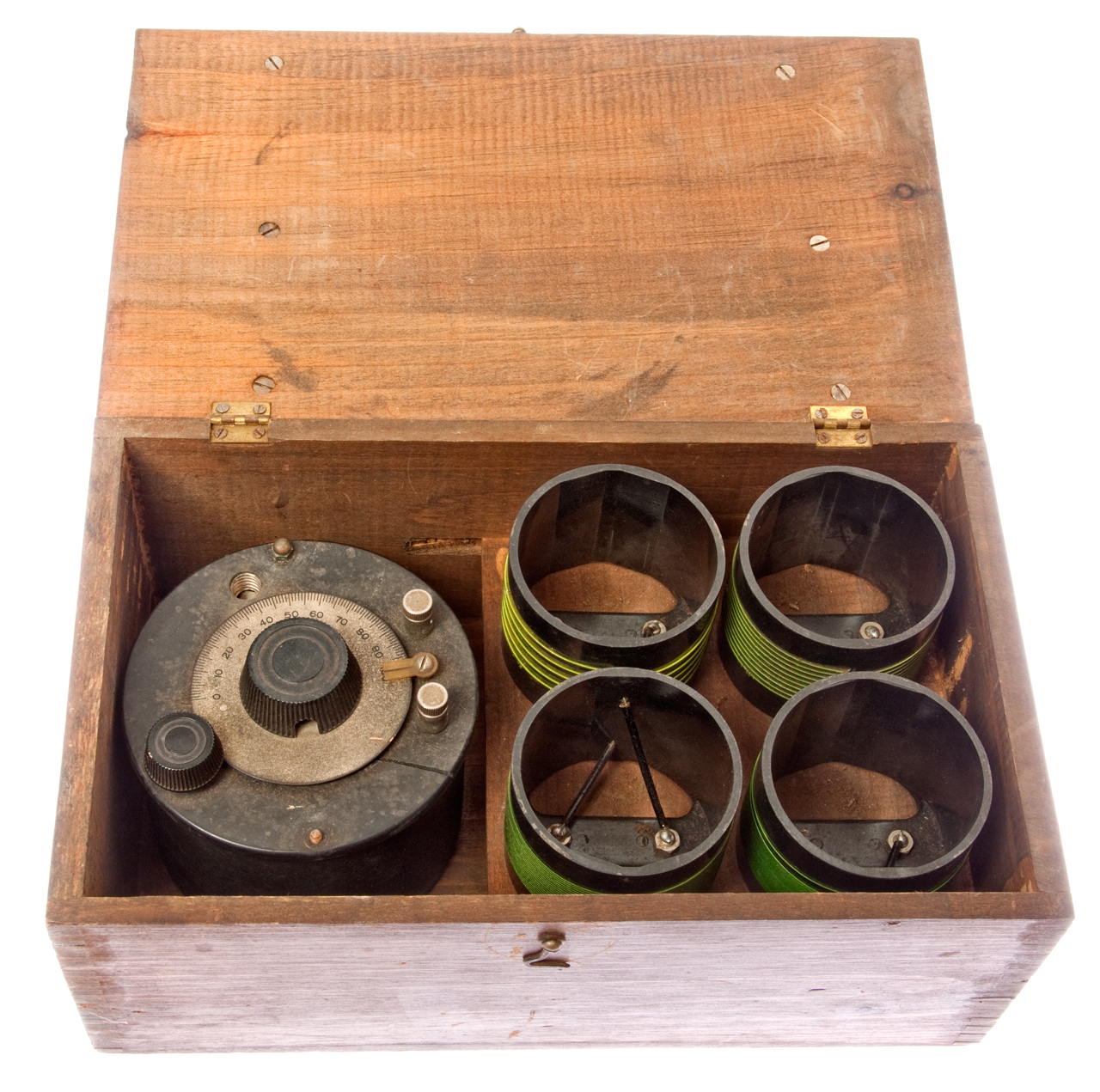
This set consists of a variable capacitor and four plug-in coils. Resonance is indicated by a minature screw base flashlight lamp (missing). The only markings are the engraved letters A, B, C & D on the coils. No label on anywhere else. The box looks home made. But the variable capacitor was manufactured to be used as a wavemeter, it is not home made. So who made this? Let me know.
The front panel of the variable capacitor was broken, but super glue has fixed it.
Capacitor
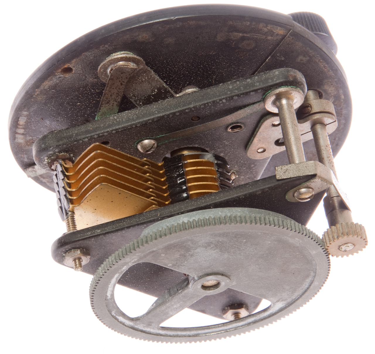
There are 6 fixed plates and 7 rotating plates. As a first approximation they are shaped like half a circle.
The fixed plates have an OD of 3.2" and the rotating plates have a diameter of 2.2".
The shaft is not centered on the rotating plates so that there is a larger range of capacitance change than would be obtained from a symmetrical arrangement. Maybe some type of liner readout?
When fully meshed there are 12 plate-to-plate gaps all with an area of the half a circle that's 2.2" diameter.
Area circle = PI * R * R = PI * 1.1 * 1.1 = 3.8 sq in or 2,452 sq mm.
A half circle would be 1,226 sq mm.
12 gaps is 14,714 sq mm.
Distance outside the rotating plates is 0.73".
The plates are 0.025" thick.
0.73 - 0.025 * (6+7) = total air gap = 0.405"
0.405 / 12 air gaps = 0.034"
So an equivalent parallel plate air capacitor would have an area of 14,714 sq mm with a gap of 0.034" (0.857mm).
An on line calculator (Daycounter) shows 152 pF.
A wild guess is the minimum capacitance is 15 pF.
Coils
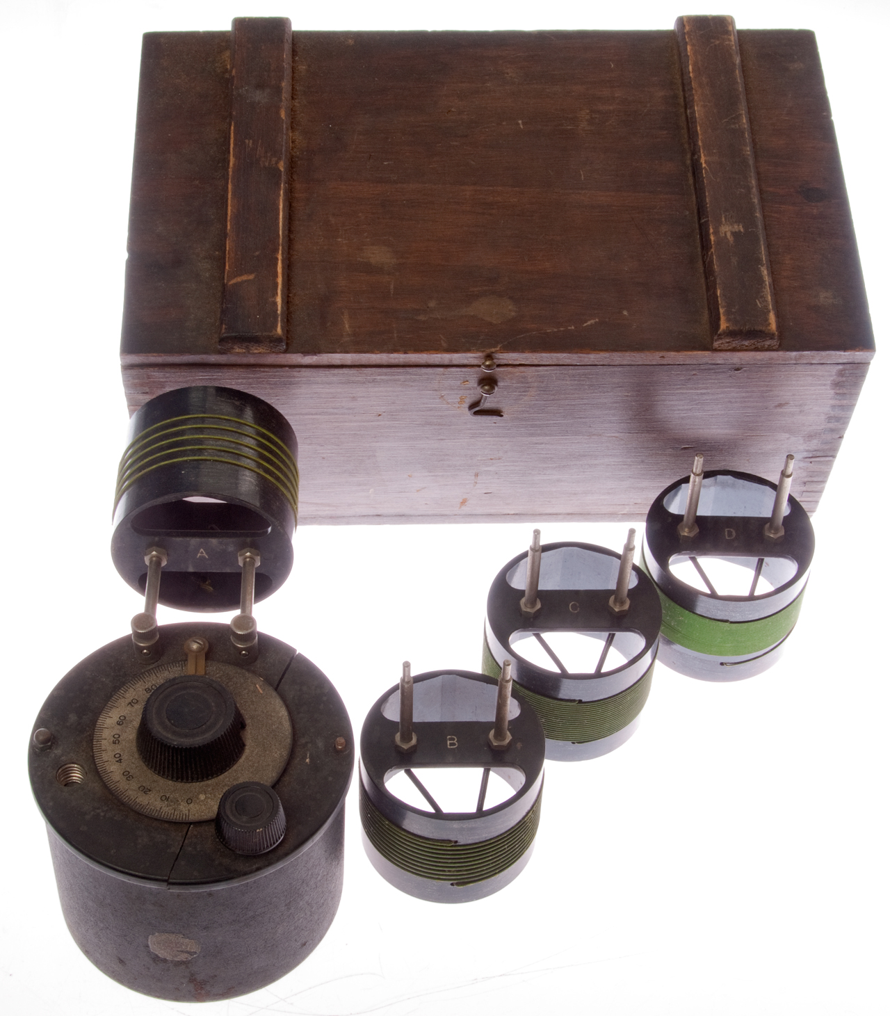
All have a diameter of 2.75" and a coil length of 1.1", but different number of turns.
Using an on line inductance calculator (IN3OTD) gives and resonance calculator (Daycounter) gives:
Coil
Turns
uH
kHz @ 152 pF
kHz @ 15 pF
A
5
80
1,440
4,590
B
10
320
722
2,300
C
20
1281
361
1,150
D
40
5123
180
574
These values seem reasonable. Early radio was in the medium frequency and lower frequency ranges, i.e. wavelengths of 1,000 meters (3 Mhz) and longer.
Note: There is an error in the above calculations, not yet sure where.
Lamps
I've found a few lamps with E10 bases and low power operation.
No. links to Bulb Town
No.
Volts
Amps
mW
40
6.3
0.15
945
48
2.0
0.06
120
359
1.35
0.06
81
The 359 looks like the best bet.
6.3 Volts AC was a common tube filament and so many pilot lamp bulbs run on 6.3.
1.35 is the voltage of a single Mercury battery (now obsolete) (Wiki) and so it makes sense that there was a lamp to run from one of these.
Note while the Wiki web page shows a Mercury coin cell, there were Mercury batteries in all the common sizes, such as "D" size.
At Aertech we built in a "D" size Mercury battery thinking that it would outlive the amplifier, but it came back some years later and we opened up the case, installed a new battery and repainted it.
It did not come back again.
Measurements
Folded up a 3x5 card and used it to open the lamp socket contacts. Connected to HP 4395A network analyzer and did a simple response calibration.
The wavemeter is now series connected and the peak is the tuned frequency.
The Marker Peak find function works for Coils: D, C & B,
but coil A has a very broad peak so to make the calibration
plots at right I needed to manually set the peak frequency.
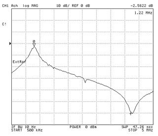
Coil D
Maximum capacitance
lowest possible frequency: 1.22 MHz
longest wavelength: 246 meters
Freq MHz
Dial
Peak Frequency MHz fairly close to the Bulletin 931 data.
Measured
Bulletin 931
Coil
Cmax
(MHz) (meters)
Cmin
(MHz) (meters)
Cmax
meters
Cmin
meters
A
(7.5) 40
(22) 13.6
28
14
B
(4.1) 73
(12.9) 23
56
26
C
(2.4) 125
(6.3) 48
114
54
D
(1.2) 250
(3.1) 97
220
105


Photos
Fig 1 Set in box
Fig 2 Coil A installed with coils B, C & D to the right

Fig 3 Variable Capacitor (flashlight lamp missing) at upper left.

Patents
2367681 Ultra-high-frequency tuning apparatus, Karplus Eduard, Arnold P G Peterson, General Radio, App: 1941-12-10, Pub: 1945-01-23, 334/67; 361/298.5 - this is the "Butterfly" patent as mentioned in patent 2578429 with the same title as this one.
This is a temporary parking spot for these patents which came up during today's search relating to GR wavemeters.
4032845 Surface wave communication system, Lester C. Via, Vitro Corp, 1977-06-28, - "...coupling radio frequency signals to and from a single wire transmission line to provide a wide bandwidth communications link between relatively moving transmitters and receivers...".
3031619 High precision multipurpose reference oscillator circuit arrangement, Tykulsky Alexander, Jonas M Shapiro, Stanley S Tulgan, Manson Lab, 1962-04-24
Related
General Radio: 650A & 1650B Impedance Bridges, Sound Measurement Equipment -
Time & Frequency -
Millen 90651 GDO
FR-149B/USM-159A Frequency Meter - latest version of BC-221
References
NIST: A Direct-reading Decremeter and Wave Meter by Frederick Kolster talk given Feb 1914 - covers the "Design of Condenser"
Links
PRC68, Alphanumeric Index of Web pages, Contact, Products for Sale
Page Created 10 July 2016