Black Box Beacon Transmitter

|
|
 |
|
|
|
something has been cut off. The On-Off switch has a notch that |
In the center of the notch is the inscription "24A" |
|
9 Volt batteries |
2020 Aug 20 - Heard from Alan Tasker that this might be part of the PRQ-4(V).
That three letters means: Portable Radio "Special or Combination". But note that for secret projects the three letters may be a deception.
Mechanical
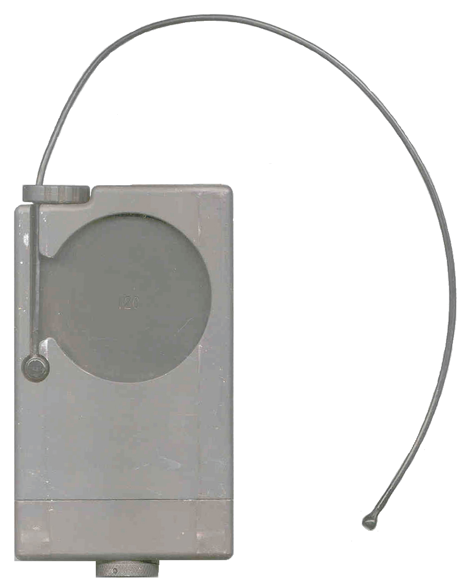
When the knurled knob on the bottom is loosened there are a couple of compartments that hold a pair of standard 9 Volt batteries. There is an O-ring seal between these two parts and a flex cable that keeps the cap from being lost.
The knurled knob has a "D" ring to allow a lanyard to be attached. The battery contacts have insulating overlays that have a large and small opening so that the battery can only be inserted with the correct polarity.
This type of battery compartment access is almost identical to that on the MS-2000M Distress Marker Light.
One face of the box has a depression that would mate to a cylinder about 11 inches in diameter. What's the diameter of a SEALS scuba tank?
The construction is much more rugged than military construction, literally a solid block of metal. All the joints are sealed by O-rings indicating that this unit can be submerged to some depth without damage, although water would severely reduce the range. The closest radio I have in terms of being rugged is the PRC-90 survival radio that uses similar construction. The ToughBook CF28, CF30 laptop computers (by comparison are wimpy.
The antenna protrudes past the case a little over 12 inches and can not be removed form the box and it is coated with a black material that may be water proof. There are no joints in the antenna, it is just a flexible wire that can be coiled up in the stowage depression. In order to stow the antenna you must turn the unit off.
The box measures 5" high, 3" wide and 7/8" thick at the edges, 3/4" thick in the center.
The PRC-90 type of survival radio has similar very robust construction, but is a slightly larger package. Note that the PRC-90 is designed to be submerged in deep water and come up working and has both voice and beacon functions, but no serial number. The newer 406 MHz survival radios do have an electronic serial number and a lot of other digital information to be compatible with satellite reception on the first pass.
The printed circuit board does not have mounting holes. It is sandwiched between the foam glued on the back of the lid and the foam glued to the box. Since the parts are surface mounted this is an excellent way to hold the board. It should stand up to much higher levels of shock and vibration than would be possible if the board was rigidly mounted. Again this points to a lot of thought put into the design. I expect it could literally be shot from a gun.
There are no parts that can get lost. Some radios have detachable antennas or battery box covers that could get separated from the main radio. There are no parts of this radio that can be separated in normal field use except for the two 9 Volt batteries, which are not part of the radio.
Lanyard Loop - There is a wire loop that folds down inside the battery cover knurled knob that would be suitable for attaching a lanyard. This is the type of thing that would be suitable to keep from loosing the Black Box, but not suitable to attaching it to something else in a permanent way.
There are no through holes, posts, notches, dogs or other hardware items that would be associated with some form of attachment hardware.
With the exception of the bar code label "M01239' that has the top part cut and the "12C" engraved in the center of the antenna storage cavity, there are no markings on the outside. The color is flat black.Electrical
9 Dec 2004 - received a copy of the schematic from Pasquale L.
It has no title block or other identifying information. The chip that has the white paint and hand written information turns out to be an LT1020 voltage regulator.
This confirms that this is a beacon transmitter. Each box has an ID number stamped on the outside and a matching sticker on the LT1020 chip inside. This is strange since all the units are electrically the same except for the actual transmit center frequency.
A block diagram would have the following:
- LT1020 voltage regulator supplying + 5 volts to
- the crystal oscillator (2 transistors)
- full battery voltage driving the CMOS circuits that generate the modulation which is just a 570 uS wide pulse at a 434 Hz repetition rate.
- The modulator turns on and off the RF power amplifier made up of a MRF966 followed by a MRF 5812 followed by an output filter.
- The LED is driven by the comparator that's part of the LT1020. The comparator is fed from rectified RF so that when the LED in on the operator knows the transmitter is actually working. This is far better than an LED driven from the modulation, i.e. you know there's RF when the LED is flashing.
ON Off Switch
The "factory" schematic shows two independent switches SW1 and SW2, but both of them are controlled by the on-off switch mechanism. It turns out that the knob of the on-off switch can be installed in two ways, and in the 24A it is installed so that only SW1, the power switch is used and SW2 is left open. In this case only the "A" and "B" inputs to the 1 of 8 4051 mux are used and the "C" input is pulled up. There is a ball bearing under the knob that supplies the detent action and probably limits the amount of shaft rotation.
The schematic legend next to SW2 is "Duty Select". I think that when the on-off knob is installed after being rotated 180 degrees relative to the shaft then the wide cam lobe activates both switches and the "C" input is fed from a 4060 output making for a 1/8 duty cycle instead of a 1/4 duty cycle. Note that the knob has 180 degree symmetry and so maybe just reversing the knob will be all that's required to make this change. Not easy to do on 24A since after removing the screw the knob does not want to come off.
The surface mount chips inside are all Motorola. The top part of the PCB is digital circuitry and the left and lower parts are the RF portion.
When the knob is turned on, the "12C" unit transmits on 164.5375 MHz and the second harmonic at 329.0685 MHz is way down.
In the upper left side of the PCB there is a crystal marked 164.5375 (I got the frequency from the spectrum analyzer and at a later time read the crystal frequency).
This is in the government frequency band for sonobuoys and outdoor intrusion detectors.
There is also a watch type tuning fork IC in the upper right corner ('89 date code) and the IC beside it is a 14060 (same as 74HC4060) which is a combined oscillator and 14 bit binary divider. This chip will divide the 32,768 Hz (or is it really 26m868 Hz) tuning fork frequency down to 2 Hz (1/2 second per tick). The next chip over is also a 14060 and is probably used to further divide the 2 Hz down to 0.2 Hz (5 seconds). The next chip over is a 14051 which is an eight to one mux and is closest to the 16 pin chip with the hand written label and is used to form the modulation for the IRFR 9020 FET that switches the DC power on and off for the RF amplifier.
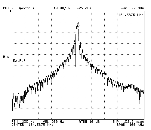
The "24A" unit transmits on 164.5875 MHz.
The transmission goes for 5 seconds then there is 5 seconds of silence. This is probably a battery saver technique. The LED on the top blinks 16 times during the 5 seconds of transmission.
The RF modulation width is + and - 100 kHz from the carrier and is best heard in the AM mode.
a 25% duty cycle pulse that's a little under 600 micro seconds wide Modulating a carrier at 164.5875 MHz produces the following spectrum.
Note that there is no commercial receiver that will receive this pulsed signal with optimum signal/noise performance.
Aircraft communications radios have a bandwidth of a few kHz nowhere near the 100 kHz plus that this signal occupies, and so do not hear it.
A commercial FM broadcast radio (88 to 108 Mhz) has the needed bandwidth, but does not tune to this frequency and it's questionable if the FM demodulator would respond. Pulsed signals are typically used in RADAR systems, but the ones I've worked with use much higher frequencies.
The box with "12C" in the center of the circular antenna storage depression has an IC with a hand written label 12 and in smaller letters 293.
The box with "24A" in the center of the circular antenna storage depression has an IC with a hand written label 24 and in smaller letters 266.
You can see from the spectrum analyzer that the modulation bandwidth is similar to an FM radio, yet most receivers that can pickup 165 MHz have a 5 kHz bandwidth and do not hear this signal.
Other known serial numbers are: 21C and 41C.
14C on outer case, Written on i/c 24, smaller numbers 298, Tx freq 164.5375 MHz.
ID#
IC#
Tx Freq MHz
12C
293
164.5375 24A
266
164.5875 14C
298
164.5375 21C
?
?
41C
?
?
Note that 12C and 14C transmit on the same frequency, yet have a different IC#.
A guess is that the IC# is some sort of serial number for the PCB.
29 Sep 2004 - the 164.5875 seems to be a strange frequency. Since the modulation bandwidth is so wide I would expect adjacent channels to be separated by at least the bandwidth of the signal being transmitted.
The LF crystal, after going through a frequency division, is used to gate a power FET which turns on and off the VHF amplifier stages.
Battery Life
23 Sep 2004 - The current draw is about 22 ma during Tx and about 6 ma during the pause for an average current near 14 ma. If a pair of standard Energizer No. 522 batteries were used the run time would be about 80 hours. The DC power to the oscillator seems to be a constant 5 Volts whenever the power switch is turned on, not switched off during the pause time, which would save power but may cause the frequency to change during the transmission period. Since the VHF crystal oscillator gets it's power from the voltage regulator, it may have been in the plan to switch off the oscillator during pause, but then the plan was changed. The amplifier power is switched off during the pause period, but during the Tx period it is pulsed 620 uS on with a period of 2.38 mS. This is strange, why was it done?
Spread Spectrum
Although the signal being transmitted is a pulse where the pulse width is 1/4 the period the effect is similar to a spread spectrum signal.
The Maxim Spread Spectrum web page talks of Time Hopping Spread Spectrum (THSS) and is a good overview of Spread Spectrum systems. Note that Direct Sequence SS and Frequency Hopping SS are the common types mentioned and that THSS is not talked about very much, but may be the simplest to do in terms of a transmitter.
Shannon and Hartley channel-capacity theorem (Wiki):C = BIf the channel capacity is the message you want to send and how fast you want to send it (in this case a single pulse sent about 434 times each second for abut 5 seconds and then about 5 seconds of silence, maybe 434 bits per second. The receiver bandwidth needs to be 150 kHz to get most of the transmitted signal, then the process gain is about 345. That means that a transmitter putting out 0.1 watts (just a guess for the black box based on 50 % efficiency, 22 ma from 9 Volts. Also the "factory" schematic shows 20 dBm as the output power.) will have an equivalent output power of > 34 watts! The signal actually covers a bandwidth greater than 200 kHz so maybe 35 Watts is closer.Log2 (1+ s/n)
C is the channel capacity in bits per second (bps), which is the maximum data rate for a theoretical bit-error rate (BER).
B is the required channel bandwidth in Hz
S/N is the signal-to-noise power ratio.
24 Sep 2004 - A rough test of output power is to use the HP 4395A Spectrum Analyzer with the OE-254 antenna as it's input. This antenna is about 75 feet from the Black Box transmitter. The SA shows the peak power at the carrier frequency of 164.535125 to be about -64 dBm. From the path loss equations below the loss for a zero distance path is about 80.9 dB so the transmitted power might be +16.9 dBm which is fairly close to +20 dBm (100 mW) guess above.
I first learned about process (or modulation) gain when home viewing of C band satellite TV started. They use a 36 MHz channel to carry a 4.5 MHz video signal in order to get the process gain, thus lowering the transmitter power needed in the satellite. FM radio has a small amount of process gain.
A Sonobuoy receiver would work, see my Sonobuoy page for more on that. Note the transmission frequencies of the black box are not exactly on sonobuoy channel 4 (164.4500 MHz). But the WiNRADiO SDR receivers sold for sonobuoy reception have an IF bandwidth of 230 kHz. It would be strange that they have such a wide bandwidth for just this application, so what other signals need that bandwidth? Maybe those that have been "spread" so that the process gain helps a satellite receive their signal? let me know.
The pulse signal sent by this unit requires a special receiver and demodulator. The receivers commonly used at frequencies around 164 MHz have IF bandwidths of at most 16 kHz and so will NOT be able to receive this very wide band signal. Conventional FM radios (88 to 108 MHz) have the required IF bandwidth, but do not tune to 164 MHz, but the IF strip would be suitable for this beacon so constructing a suitable receiver would not be that difficult.There may be geostationary satellites that can receive these transmissions, a wild guess, but it makes more sense than having large aircraft flying on a 7/24 basis and the huge and very expensive supply chain that goes with it. Note that a constellation these satellites could also be used by the Navy to monitor sonobuoys anywhere in the world, or the Army, Navy or Marines to monitor ground based sensors.
Satellite Orbits & Path Loss (back of the envelope calculations show signal too weak to hear)
Geostationary or geosynchronous orbit (GSO) satellites are at about 35,700 km (22,182 miles) above the Earth.Geostationary (GSO) or geosynchronous satellites = 36.6 + 20*Log(164.5) + 20*Log(22182) = 36.6 + 44.3 + 86.9 = 167 dB
Low Earth Orbit (LEO) is in the range of 300 to 1200 km (186 miles).
The Path loss is given by:
dB = 36.6 + 20*LOG(MHz) + 20*LOG(miles)
So the path loss at 164.5 MHz would be:
LEO satellite = 36.6 + 44.3 + 45.4 = 126 dB
35 Watts = 35,000 milliwatts = 45 dBm
45 dBm Tx power - 126 dB path loss = -81 dBm signal in space near a LEO
Noise in a 50 Ohm system is given by
Watts of Noise = k * T * B
k is Boltzman's constant = 1.381E10-23 W/Hz/K,
T is temperature in Kelvin
B is bandwidth in Hz
So the noise level in the LEO spacecraft might be -92 dBm assuming the satellite is kept at about 290 K (17 c) room temp and it's using an isotropic antenna (no antenna gain can be used since the satellite is very close to the Earth.).
The s/n might be -81 dBm / -92 dBm or 11 dB, which is a noisy signal.
So it looks like a LEO might be able to receive this beacon transmission.
Note that the GSO satellite has 41 dB more path loss so with no antenna gain (like was used for the LEO) at first it looks like the signal would be too noisy to hear, but a gain antenna can be used on the GSO 22,182 miles above an Earth with a diameter of 7,900 miles (26,132 miles to the Earth's center) means the half angle from the center of the Earth to the edge is about 0.6 degrees.
The area of a sphere is 4 * <PI> * R2 or the sphere with the GSO at it's center and the Earth on the surface would have an area of 8.58E9 square miles. The Earth disk area on the surface of the larger sphere would be <PI> R2 or 4.9E7 sq miles. So the fraction of the big sphere covered by the earth is 4.9E7 / 8.58E9 or 0.0057 so an antenna could have a gain of 175 times (1/0.0057) which is 22 dB and still cover all of the Earth. Note that some GSO sats have beams that are much smaller than the Earth, for example Japanese TV sats have a beam that just covers their island system. If a higher gain antenna that could be steered was used then the s/n could be improved.
So the signal after the full Earth coverage antenna on a GSO might be 45 dBm Tx power - 167 dB path loss + 22 dB antenna gain = -100 dBm. The s/n might be -100 / -92 or -8 dB, which is not useable.
So a geosynchronous satellite can not hear this signal.
The construction is essentially a solid block of metal, more rugged than military survival radios
This unit would survive a medium sized explosion.
What would deserve this level of reliability or what environment would demand this?Why does the On-Off switch capture the antenna? This cost a lot of extra money.
Once the antenna is captured it tends to hold the switch in the On position, i.e. it will not accidentally get turned off.
The shaft connected to the On-Off switch looks like it came from a big tractor, that is to say it is way stronger than what is needed to survive a grunt operator.One thought is that transmit frequency is in the band used by sonobuoys and so might be received by Navy aircraft equipped with sonobuoy receivers.
I'm not aware of any other transmitters in the VHF range that transmit a pulse, although it's common in radars.
Another thought is that is could be attached to a package that was delivered by parachute and used to find the package.
An extension of that idea would be to attach the Black Box to an object like a parachute retarded seismic Sensor that would penetrate the ground when it landed, but the rear part would still be out of the ground. The main body would be hollow and contain supplies for a spy. But the spy would need a very specialized receiver, maybe disguised as a normal FM radio.
10 Dec 2004 - since a pulse of RF is being transmitted this may be part of a bistatic radar, i.e. a radar where the transmitter and receiver are separated. The receiver would need to pickup the direct signal from this transmitter and also look for any signals in addition to the direct signal. This might be used in some type of intrusion detection system where any change the the reflected signals would trip an alarm.
19 May 2006 - It might be intended for use by scuba divers since all the corners have been smoothed and there are no sharp edges.
4 May 2008 - Personal Radio Location beacons use a pulse (typically 18 ms long and around once per second) transmission in the 142 to 216 MHz range. But these can be received by a common narrow bandwidth receiver.
Jan 2017 - A drop zone location beacon. These need to have a transmitted signal that's difficult to detect, so this pulse works well.
See the CIA documents on the Drop Zone Assembly Aid System web page.
Not Undercover tracker to be worn by a person
This transmitter is definitely not designed to be small and light as would be the case for an undercover device.There are no ID labels outside or on the PCB, this would not be a factor for an undercover device but would be important if an enemy found it, they could not prove who placed it. The HT-1 Vietnam village radios have no markings because they were intended for use behind enemy lines.
If a undercover agent is found to be carrying a wire it makes no difference what brand name is on the wire.
Not tracker for suspects vehicle
The very robust construction may suggest that it is designed for use on a vehicle rather than on a person but,
if it were designed to be placed on a suspects vehicle there would be magnets and/or loops to aid in quick attachment.
This unit has a smooth exterior that makes it comfortable to hold/carry and the antenna stows inside it's outline.
page created 8 Feb 2002.