CRT-1B Expendable Radio SonoBuoy (ERSB)
© Brooke Clarke 2014 - 2025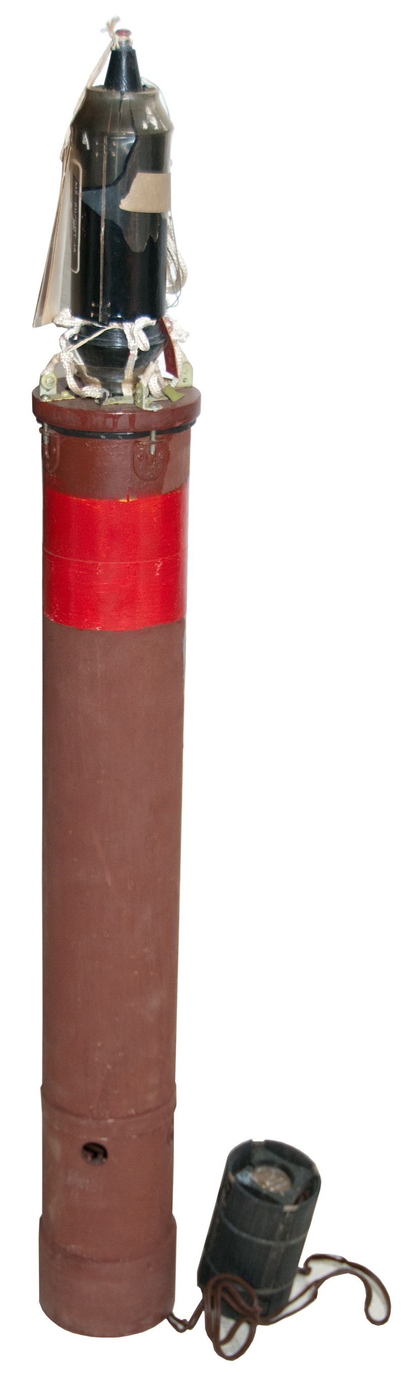
Fig 1
A couple (GSQ-154, GSQ-160) of the outdoor Intrusion Detectors from the Vietnam era use cylindrical modules that seemed to come from Sonobuoys so I tried to find the sonobuoy that was the source, but so far have not found it. My Sonobuoy web page has information on a few buoys as well as Vietnam era equipment that was re-purposed for outdoor intrusion detection. In the process of making that web page I learned that the CRT-1 was the first U.S. sonobuoy and was lucky enough to get one.
Sonobuoy transmits an FM modulated signal:
CRT-1A: 67.7 to 71.7 MHz
CRT-1B: 62.9 to 66.9 MHz (note this sonobuoy has a RED band)
Used with the AN/ARR-3 twelve channel receiver. Used in conjunction with the AN/ASQ-1 MAD equipment.
In 1942 Magnetic Anomaly Detection (Wiki MAD) was invented (see Sonobuoy MAD patents) but it could not tell the difference between a sub near the surface and a much larger ship on the bottom. The sonobuoy was the answer to that problem. The CRT-1 was first put in service March 1942. The CRT-1 could only detect a sub if the propeller was cavitating. Under the best of conditions the range was about three and a half miles. (Wiki)Ref 1.
I believe this was used as the basis of the Project Mogul "flying disks" used to listen for atomic explosions and/or missile launch noises in the stratospheric sound channel. For more on this see my Roswell Connection paragraph on the Sonobuoy web page.
I have another web page for Torpedoes, depth charges, mines and hedgehogs, Submarines, VT Fuze, Sonobuoys, SOSUS,
The CRT-2 was a jammer. In the 1950s I had the clock mechanism from what I've just learned was the CRT-2 jammer.
The CRT-3 is known as the Gibson Girl lifeboat radio because of its shape.
For an excellent example of the use of sonobuoys see sonobuoy Ref 51: the sinking of I-52.
First
This was the first operational sonobuoy (ever or just the U.S.? tell me).
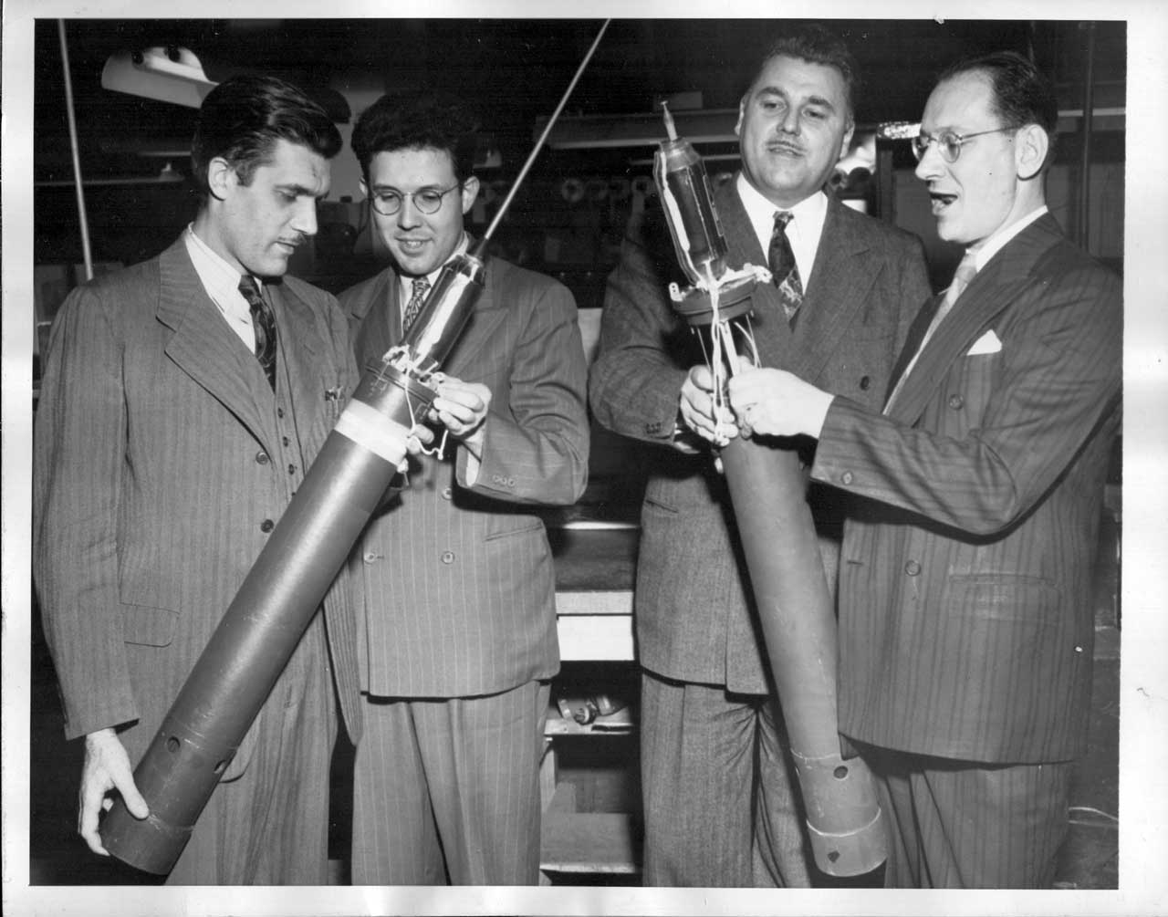
Press Photo
Left to right:
Arthur Gremer, Design Eng;
Francis Burger, Supervising Engineer;
George Rogers, Chief Engineer, and
Mark Grant, Design engineer.US Navy Secret Weapon Found U-Boats
Use of an instrument called a sonobuoy, Emerson Radio's development for successfully detecting submerged U-Boats, was made public by the Navy in recent announcement. The Sonobuoy is a small radio-equipped buoy which, when dropped by plane near a submarine, broadcast a faithful recording of the submersible's underwater progress. Each buoy's "Broadcast" and location was known. By dropping a number i path of the submarine, it was siple to "chart" the sub's progress. When it surfaced a plane was usually overhead to drop bombs on it. emerson engineers responsible for the development of the sonobuoy are shown with the instrument, given much credit in crushing the Nazi U-Boat campaign in the Atlantic. Left to right:
Arthur Gremer, Design Eng; Francis Burger, Supervising Engineer; George Rogers, Chief Engineer, and Mark Grant, Design engineer.
BU
Credit Line (ACME) 10-26-45
While Emerson Radio (Wiki) is mentioned I can not find any information that ties them to Sonobuoys. Prior to W.W.II they made phonographs. During the war they worked on RADAR and after the war on television.
There is a section on sonobuoys in the book US Naval Weapons, Norman Friedman, 1983 (Sonobuoy Ref 19).
"...ordered by the Army in qantity in Jone 1942; operation began in August. The early buoys were color-coded for six distinct radio frequencies, with power limited to half a watt for line-of-sight operation. They used a 30ft deep hydrophone (a compromise between size and interference from wave noise) to listen Omni-directionally to all acoustic frequencies between 100 cycles and 10kc."
Roswell Connection
When investigating the connection between the Underwater Locator Beacons used on aircraft black boxes, like for the MH370 disappearance, I discovered the underwater sound channel and it's parallel upper atmosphere sound channel that led to the MOGUL balloon flights. More on this on my sonobuoy web page.
But now it has come full circle in that the CRT-1 was the payload used to listen for the Russian atomic bomb testing. This shows up in the book Roswell Report: Fact vs. Fiction in the New Mexico Desert, 1995, R.L. Weaver USAF. Sonobuoy mentions:
(note the use the spelling Sonabuoy instead of the more modern sonobuoy)
page
Printed
page
Document
38, 39
26, 27
Report of Air Force Research Regarding the "Roswell Incident"
195, 196, 211, 231, 232
15, 16, 31, 51, 52
Transcript from 8 Jun 94 Interview w/ Proffessor Charles Moore
pg31 "Pi Ball" should be PIBAL
272, 273, 275, 277
na
Synopsis of Balloon Research Findings
The Roswell Incident (pg 268)
"regular sonobuoy"
"Watson Laboratory scientists utilized an AN/CRT-1 Sonabuoy" (sic)"
344
9
NYU Tech Report NO. 93.03
Constant Level Balloon Project
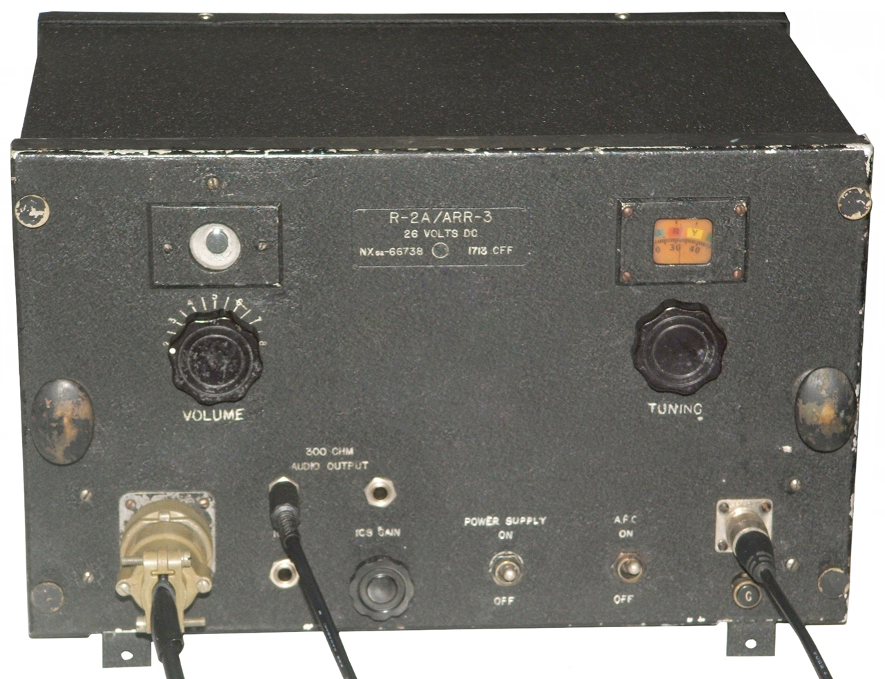
R-2A/ARR-3 sonobuoy receiver has AFC
707, 716, 717, 718
2, 11, 12, 13
Journal Transcripts A.P. Crary
"sonobuoy worked into GR3"
put McCurdy low frequency amplifier in circuit before GR8 and have plenty of signal
9 June 1947Sid West's ranch: recovered sonobuoy, microphone, and lower part of dribbler.
Aug 6, 7, 8 1947 - Flight 25B depended on sonobuoy signal
pdf pg 275
"1. Descriptions of the debris provided by Brazel, Cavitt, Crary's diary, and the photos of the material displayed in General Ramey's office. These materials were consistent with the components of a MOGUL service flight, with neoprene balloons, parchment parachutes, plastic ballast tubes, comer reflectors, a sonabuoy, and a black electronics box that housed the pressure cutoff switch (Atch 3). "
pdf pg 277
"THE "COVER STORY"
From research, it appears that the wreckage displayed on July 8 consisted of unclassified components of a MOGUL balloon assembly. Possibly withheld, if it was indeed recovered, was the AN/CRT -1 Sonabuoy, which could have compromised Project MOGUL. Although the Sonabuoy was not itself classified, its association with a balloon would have exposed a specific military purpose, an obvious violation of project classification guidelines (Atch 9). A device described in "crashed disc" publications as "a giant thermos jug" was allegedly transported from Fort Worth AAF to Wright Field.38 This description is consistent with the appearance of an AN/CRT-1 Sonabuoy such as was used on flight no. 4 (Atch 4). At some point General Ramey decided to forward the material to Wright Field, home of AMC, the appropriate agency to identify one of its own research devices or a device of unknown origin. If the debris was determined to be from an unknown source, the AMC, T -2, Intelligence or Analysis Division, would conduct scientific and/ or intelligence analysis in an attempt to discover its origin. But since the balloons, reflectors, and Sonabuoy were from an AMC research project, the debris was forwarded to the appropriate division or subdivision, in this case the Electronics Subdivision of the Engineering Division. There, it was identified by Colonel Duffy, under whose purview Project MOGUL operated. Colonel Duffy, a former project officer of MOGUL with specific directions to "continue to monitor upper air programs," was the appropriate headquarters officer to make an identification, which he apparently did. According to Captain (now Colonel) Trakowski, the officer who succeeded Colonel Duffy as project officer on MOGUL, after returning from the Alamogordo II field trip, Colonel Duffy contacted him by phone at Watson Laboratories and informed him that the "stuff you've been launching at Alamogordo," had been sent to him for identification. He described the debris to Captain Trakowski, and Trakowski agreed that it was part of his project (MOGUL).39"
Notice in the description below that the sonobuoy is a derivative of the radiosonde. It's interesting that the first sonobuoy was also deployed as the payload for this project But there were at least two modifications:
- The normal batteries were replaced by a much larger battery pack to last the many days of the flight time.
- The hydrophone may have been replaced with a "disk microphone" - please tell me about this
The idea was influenced by the work of Dr. Thomas H. Johnson of the Bartol Research Foundation of the Franklin Institute who used telemetry to get data from high altitude balloons (Bartol: Hodoscope 1933). By the early 1930s the expendable meteorological Radiosonde (Wiki) carried a simple radio transmitter using a vacuum tube and dry batteries. The chronometric type was in use where multiple channels were being transmitted. This technology was mentioned in a (18 May 1941) letter from Professor P.M.S. Blackett (Wiki) to C.G. Darwin (Wiki) and the follow on letter from Darwin to the U.S. National Defense Research Committee (Wiki: NDRC) on 24 May 1941. At this time the Magnetic Detection System (MDS, now called MAD) only had a range of about 200 feet so was of no use in tracking a sub from a plane. See Sonobuoy Ref 7 pg 31.
The expendable sonic buoy (Wiki) and the Magnetic Airborne Detector (as they were called then) (Wiki) came out of a project of the NDRC (Wiki) Section C-4. See Ref 2 page 181 - 184.
2397844 Signaling apparatus, Dewhurst Wallace W (Haddon Heights, NJ), Rca Corp, Filed: Oct 1, 1942, Pub:Apr 2, 1946, 367/3, 138/89, 114/198, 455/99, D10/107, 441/11, 73/322.5 - This may be THE sonobuoy patent. Ref 2 says RCA developed the first convey buoy which was to be dropped from the stern of a ship and would detect any sub that came up from behind the convey, which was the MO of "Wolf Packs", but these were soon replaced by the air dropped type.
Note 19 patents cite this one as prior art.
Note that a sonobuoy is not a weapon, that's to say it can not damage an enemy submarine. Once the sonobuoy detects a sub then some munition needs to be used. Although there were some attempts made to use bombs these failed since dropping a bomb from a moving aircraft and hitting a moving submarine or ship is almost impossible with a ballistic bomb. The depth charges (Ash Cans) used early in W.W.II had a very slow decent rate and so were not very effective. The later streamlined depth charges worked better, especially when fitted with contact or functional influence fuzes. But the most effective munition was the torpedo and later extremely effective the FIDO Mk 24 depth charge (Wiki) (actually a sound homing torpedo).
YouTube Title:
Navy Depth Charge Demonstration (1946) - really about CRT-1 Sonobuoy. THe CRT-1 probably could only detect a sub at high speed (cavitating Wiki). Note the use of "Ash can" depth charges that had a poor record because a can with its centerline axis horizontal descends slowly. It was replaced with the Mk 9 depth charge that was shaped like a bomb and included tail fins, much faster decent giving subs much less time to get away.
From Sonobuoy Ref 6 "In June 1942, the first operational passive broadband AN/CRT-1 sonobuoy, shown in Fig. 2, was issued. The operational frequency of the AN/CRT-1 was 300 Hz to 8 kHz within the frequency range of the human ear and processing of the transmitted signal was aural. The operator had to make real-time decisions based on his ability to distinguish various underwater sounds. The AN/CRT-1A, an improved version, also known as the Expendable Radio SonoBuoy (ERSB), had an increased frequency band of 100 Hz to 10 kHz and lighter weight (12.7 pounds). The suspension cable was stored inside the hollow shell to reduce the buoy length by 4 inches (to 40 inches overall) from the earlier design.11, 17, 18, 19
Upon launch, a static line attached to the airplane tore off the parachute cover to allow the orange 24-inch diameter parachute to open. The antenna telescoped and protruded through a hole in the parachute. The antenna was a 39-inch quarter-wave steel tube, with about 9.5 inches of the antenna insulated from the water by a watertight sleeve. One of the parachute shrouds pulled a switch pin to turn on the transmitter. In the water, the parachute remained attached and settled around the antenna base.20 The amplifier and RF transmitter inside the sealed upper compartment were mounted on either side of a rectangular plate with the audio amplifier on one side and the RF circuit on the other. The plate was mounted on four shockproof rubber supports to isolate the circuitry from microphonic noise, and each vacuum tube socket had its own rubber mounting. The FM transmitter provided an effective RF antenna radiation of 0.1 watt. It was powered by four parallel 1.5-volt flashlight cells for filament voltage and two series 67.5-volt miniature batteries for plate voltage, providing 4 hours continuous operation.20
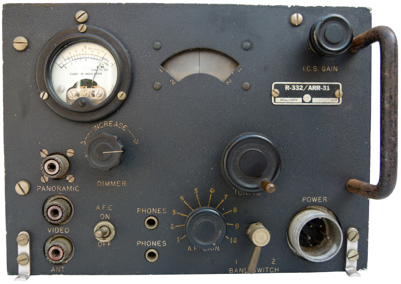
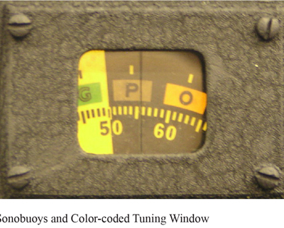
by 1944, the Navy had ordered 59,700 AN/CRT-1A sonobuoys. These sonobuoys were manufactured with six RF channels. Each channel corresponded to a color (purple, orange, blue, red, yellow, and green) and was received on the AN/ARR-3 receiver, which the operator manually tuned (Fig. 3) in one buoy at a time using the color-coded tuning window to compare the intensity of the sound. Automatic Frequency Control (AFC) allowed rapid tuning for comparative listening.13, 29, 30, 31"
From Fig 3 R-2/ARR-3 Aircraft Receiver
First sonobuoy, dropped from a ship in a convoy
Green: 46 MHz
Purple: 54 MHz
Orange: 62 MHz
These were proof of concept units first used September 1941 and weighed 60 pounds. The key motivation in 1941 for the sonobuoy was that other detection methods like Visual, RADAR or ASDIC (active SONAR) resulted in the submarine escaping 95% of the time. See Sonobuoy Ref 7 pg 23.
1696109 Electric stopping device for stretching machines, Dewhurst William (Methuen, Mass), not assigned, Dec 18, 1928, 26/74, 192/126 -
1879294 Tuning indicator, Dewhurst Wallace W (Haddon Heights, NJ), Jones Nevell R, Gen Electric, Sep 27, 1932, 116/262, 74/10.7, 361/300, 74/568.0FS, 74/568.00R - string drives pointer type
2023517 Electrical resistance device, Creager Frederick L, Dewhurst Wallace W (Haddon Heights, NJ), Rca Corp, Dec 10, 1935, 338/319, 439/549, 338/332, 248/201, 439/560, 29/854, 338/327, 338/322, 29/838 - leads form solder points for terminal board (but requires slot in board).
2037620 Binding post, Wallace W Dewhurst (Haddon Heights, NJ, Eskuchen Frank, Rca Corp, Apr 14, 1936, 439/816, 220/DIG.400 - hollow post maybe for use on terminal board.
2503100 Adjustably tuned coupling unit, Bennett Paul R, Dewhurst Wallace W (Haddon Heights, NJ), Rca Corp, Apr 4, 1950, 334/65, 336/136, 334/74 - slug type coils
2555475 Radio receiver tuning mechanism, Dewhurst Wallace W (Oaklyn, NJ), Rca Corp, Jun 5, 1951, 455/178.1, 334/77 - tunes two slug type coils in such a manner that as one coil goes up in inductance the other coil goes down, like needed for tuning the input and oscillator circuits.
Related
3130384 Artificial target, Atchley Raymond D, Downs George W, Secretary of the Navy, Filed: Mar 27, 1946 (18 year delay) Pub: Apr 21, 1964, 367/1, 236/68.00B, 114/25, 434/6, 116/27 - cites the 2397844 Signaling apparatus patent as prior art. This device can be launched from a torpedo tube and simulates a submarine as a decoy for destroyers or in can be used to train destroyer crews in sub hunting.Second, air dropped sonobuoy
First operational sonobuoy as of August 1942 and by the war's end about 60,000 had been made. (Sonobuoy Ref 7, pg 39)
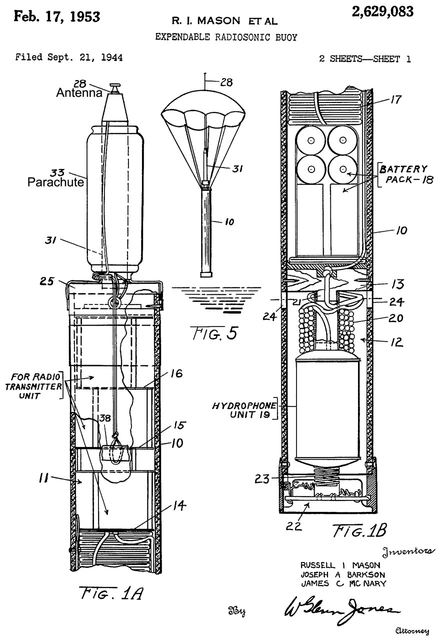
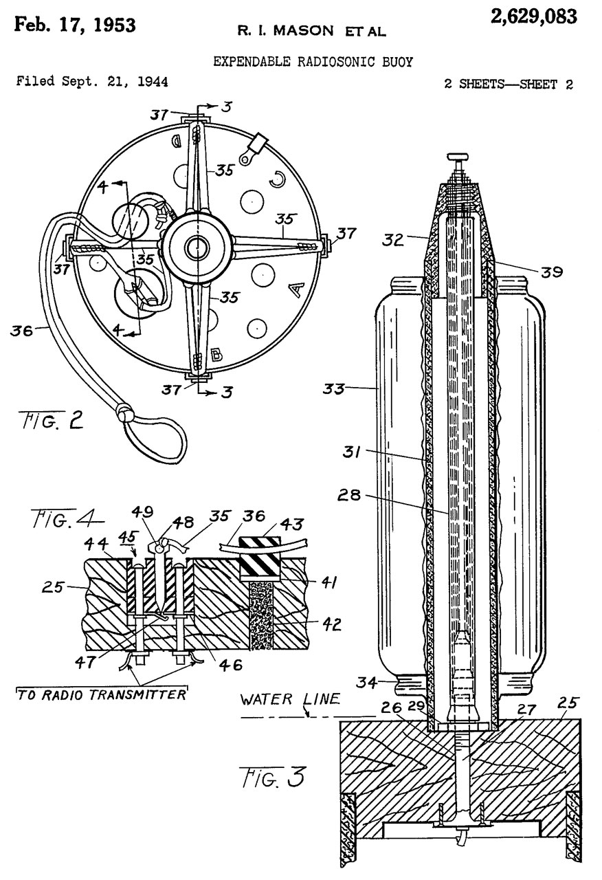
2629083 Expendable radiosonic buoy, Barkson Joseph A, Mason Russell I, Mcnary James C, Secretary of the Navy, Filed: Sep 21, 1944, Pub: Feb 17, 1953, 367/3, 343/709, 455/99, 441/33, 441/23, 343/705, 343/901 -
Versions
From Ref 4.
Designation
Audio (Hz) CRT-1
300 to 8,000 CRT-1A
100 to 10,000
CRT-1B
?
Geometry
When the aircraft was at a few hundred feet altitude (so that the MAD detector will work) the radio range for hearing a CRT-1 was about 10 miles. The hydrophone had a range of 200 to 3,000 yards. (Sonobuoy Ref-7, pg 39).
Pattern used with Non-Directional Sonobuoy
Notice that the operational depth of a submarine was on the order of 1 to 3 times its length. The MAD detector required the airplane to fly at or below 500 feet above the surface (200' for the early versions). Once the MAD detected a sonobuoys would be dropped to both mark the area and also to locate the sub by dropping a pattern of buoys.
Overall
Physical
Just under 40" tall with the antenna collapsed and eleven pounds without batteries or the shipping tube. Tube is just over 4-1/4" diameter. The size envelope was determined by the British 500 pound bomb (Wik) since a bomber would be used to drop the sonobuoye.
The telescoping antenna was frozen as received. I've applied a few drops of Kroil and maybe tomorrow it will fully extend.
Surrounding the antenna at the top is a black plastic cylinder about 6" high and 2-5/8" diameter inside of which is a coiled up synthetic rope which I guess was attached to a parachute prior to deployment from an airplane. It's marked MX-211/CRT-1A. Note the "A" was not changed when the sonobuoy was upgraded.
The hydrophone appears to be made from some type of wire wrapped around a hollow ferrous cylinder 5" tall by 3" outside diameter. It's connected to the main body by what looks like common household AC power line cord. Normally it would be held inside the bottom of the tube but it came out when the sonobuoy was removed from the shipping tube and since the wire is now very stiff it would break into bits if forced back into the tube.
Vacuum Tubes
The three 1L4 tubes for audio amplification and FM modulation and the 3Q4 RF oscillator and 3A4 final RF amp tube all have their filaments wired so they can be powered from a 1.5 Volt Zinc Carbon battery. The RF oscillator and amplifier run directly from the B battery (135 Volts), but the 1L4 tubes have a voltage divider so they run at a lower voltage.
Capability
The cord between the body and hydrophone was to reduce the noise caused by the sea lapping against the body. Down 24 feet the hydrophone was more sensitive. Note there was no amplifier down with the hydrophone. For the CRT-1 to detect a submarine it needed to be traveling at cavitating speed. Note that as the depth gets deeper the speed of cavitation goes up, so a sub can go faster without cavitating as it goes deeper. Ref 5
Detection Range
Speed
Depth
Sea State
3 1/2 Miles
7 knots
60
calm
90 Yards
3 knots
250
rough
Manual CRT-1A
CO-AN 08-30CRT1-2
Handbook of, Maintenance Instructions, for, Radio Transmitting, Equipment AN/CRT-1A
CONFIDENTIAL
1 May 1944Stapled to the inside of the cover is:
Revision sheet, 11 October 1944.
Changes some resistors and a capacitor value.
Bibliography of Scientific and Industrial Reports, May 3, 1946, No. 17
U. S. WAR and NAVY DEPARTMENTS . AIR COUNCIL OF THE UNITED KINGDOM. Handbook of maintenance instructions for radio transmitting equipment AN/CRT-1A. (CO-AN 08-30CRT1-2).
PB 14827. 1944. 40p. price: Microfile-50c - photostat-$3.00
Radio transmitting equipment AN/CRT-1A is a self-contained miniature broadcasting station in the form of a buoy whose function is to broadcast by radio the underwater sounds made by a submarine. The buoy is launched from suitably equipped aircraft into water where it can detect the sounds of a submarine, thus aiding in a more effective submarine search and attack. The complete transmitting equipment consists of the following elements: Radio transmitter T-1A/CRT-1, vacuum tube set; battery set. Installation and adjustment, mechanical and electrical characteristics, and maintenance are discussed in this report. A revision sheet is attached to the front cover. Curves, photographs, and diagrams illustrate the text.
pg 3: The CRT-1A works with the R-2/ARR-3 receiver.
pg 11" 300 to 8,000 Hz audio.
pg 13: "Transmitters are tuned to six different carrier frequencies. For purposes of security the frequency is not shown on the buoy but is indicated by a colored band. Table II matches the Frequency plan table for the CRT-1A. Trivia: there is a faint printed check mark after Purple and Green. Why?
_ NAVSHIPS 94200.1 Directory of Communication Equipment - Unclassified
Thanks to Nick England who is behind the Navy Radio web page. While specializing in surface ships, some related stuff is also there.
CRT-1 family one listing (CRT-1-1A-1B-94200.pdf)
Functional Description:
The AN/CRT-1, AN/CRT-1A and AN/CRT-B are self-contained miniature radio transmitters in the form of a buoy which detect and transmit the underwater sounds made by a submarine. They are used with Radio Receiving Equipment AN/ARR-3 or Radio Set An/ARR-16 series.
The AN/CRT-1 and AN/CRT-1A are preset to operate on one of six frequencies and the AN/CRT-1B is preset to operate on o ne of twelve frequencies within their frequency ranges. Both units are color coded to indicate their frequency.
The buoys are launched from aircraft and dropped by parachute to the water. Upon opening, the parachute checks the fall of the buoy, and by tightening of the shroud lines releases the power switch turning on the transmitter. The impact of the buoy, striking the water operates the hydrophone release, which drops the hydrophone 24 feet below the surface.
No field changes in effect at the time of preparation (2 October 1957).
ARR-3 two listings (ARR3-94200.pdf)
Radio Receiving Set AN/ARR-3
FUNCTIONAL DESCRIPTION:
The Radio Receiving Set AN/ARR-3 is designed as an airborne radio receiver with an extended audio frequency range, and is capable of receiving frequency modulated (FM) signals throughout the range of 67.2 to 72.2 megacycles (MC), in the 150 kilocycles (KC) band. No field changes in effect at time of preparation (In December 1961)TYPE OF EQUIPMENT: Airborne.
EQUIPMENT PURPOSE: The reception of FM signals.
NUMBER OF BANDS: 2 bands.
OPERATING FREQUENCY RANGE: 67.2 to 72.2 mc (only CRT-1 and CRT-1A); 150 kc band.
OPERATING POWER RQMT: 12 v dc. or 24 V dC.
Radio-Receivers AN/ARR-3B
FUNCTIONAL DESCRIPTION:
The /??/ARR-3B is a frequency-modulated (FM), airborne, radio receiving equipment designed for use in conjunction with Radio Transmitting Equipments AN/CRT-1A and AN/CRT-1B. The transmitters have hydrophones for detecting sounds of submarines. These sounds are transmitted on frequency bands to which the receiving equipment is tuned. These receivers together with their associated transmitters enable an airplane in flight to ascertain the approximate positions, within a given area, of a submerged submarine. No field changes in effect at the time of preparation (29 August 1960).
Photos
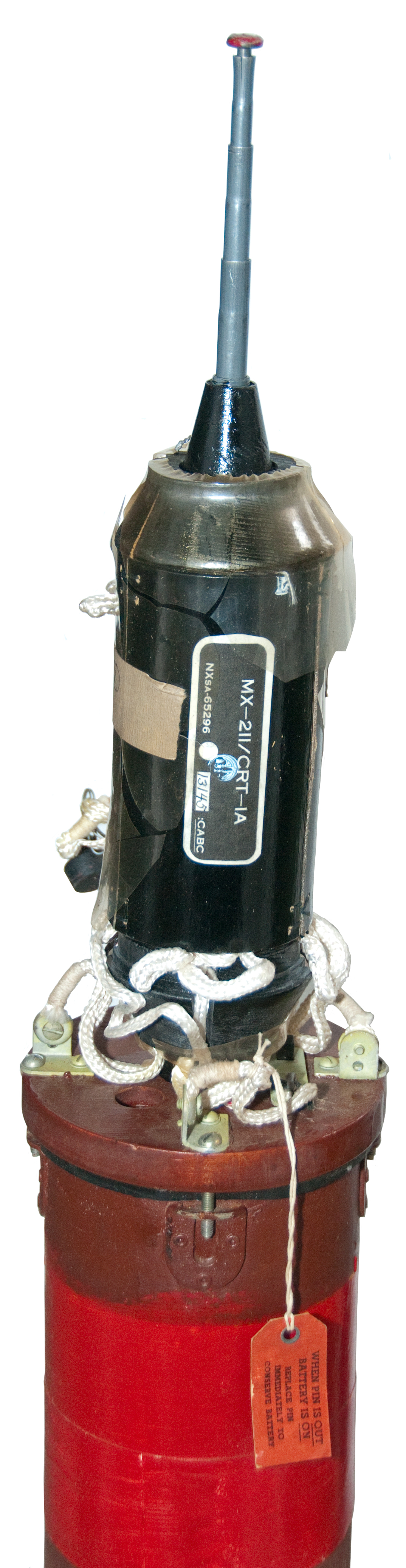
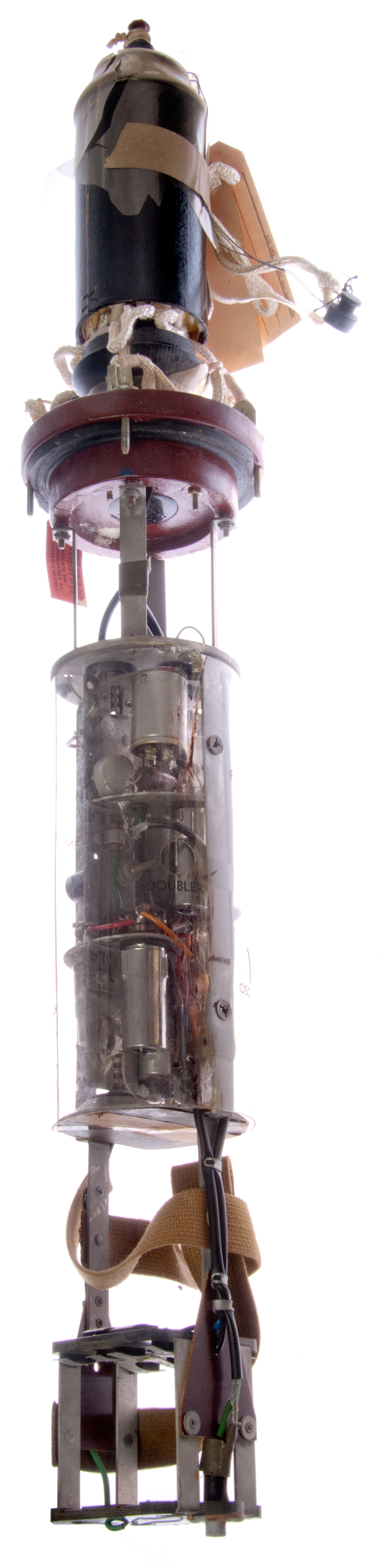
Fig 1 Overall
CRT-1B Sonobuoy shown outside the shipping tube.
Antenna all the way down.
The hydrophone has come out of the bottom and probably will not go back in because the wire is brittle.
Wire length said to be twenty four feet.
Fig 2 Top
The telescoping antenna has been pulled part way out.
Said to be about one meter long when extended. A 1/4 wavelength antenna 1 meter long means a wavelength is 4 meters or about 75 MHz. (Mc back then).
At the left you can see a small black rubber plug. Function unknown.
Rad Tag Reads:
WHEN PIN IS OUT
BATTERY IS ON.
Replace pin immediately
to conserve battery.
Note: tag connected to one of the parachute shrouds and that shroud connected to short (1/2" long) pin that will be pulled when the parachute deploys. In order to reinstall the pin a spring loaded plate needs to be moved to uncover the hole in the top.
Label reads:
MX-211/CRT-1A
NXsa-65296, 13415 :CABC
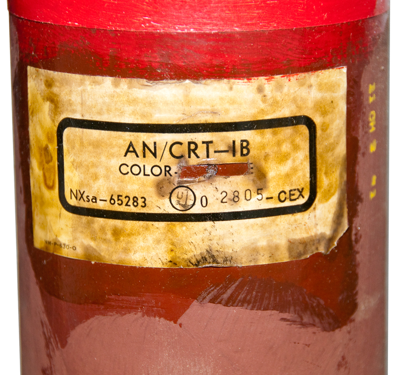
Fig 3 Main Label
AN/CRT-1B
Color <red> (related to transmission frequency)
NXsa-65283, 2805-CEX
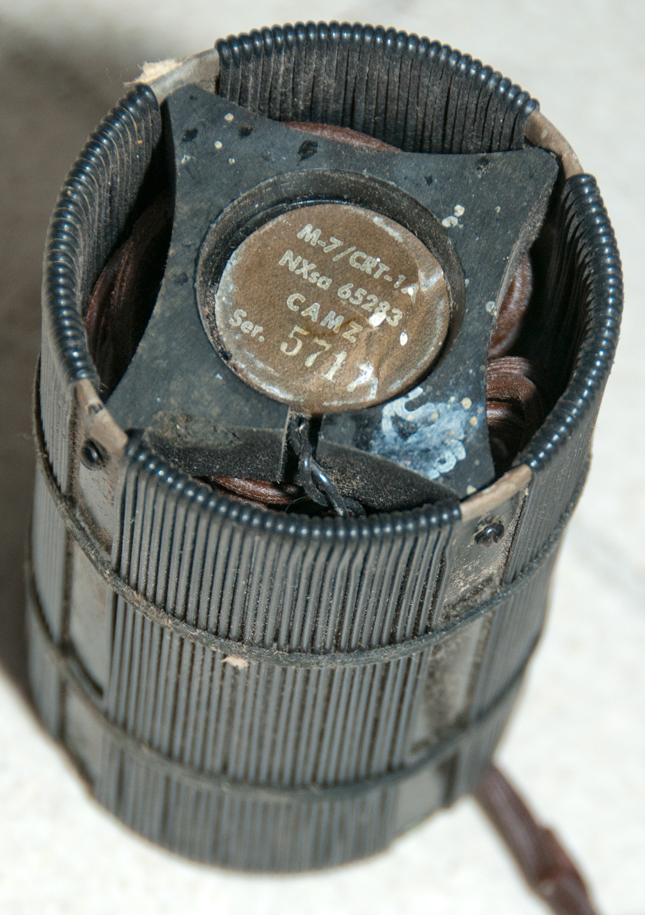
Fig 4 Hydrophone (Wiki)
5" tall x 3" dia. Nickel cylinder wrapped with wire. There's a permanent magnet inside the hydrophone (a nearby compass is strongly influenced).
Label:
M-7/CRT-1A
NXsa 65283
CAMZ
Ser. 5717
Patents
942897 Apparatus for receiving submarine sounds, Thomas Alexander Garrett, William Lucas, Dec 14, 1909, B06B1/08
Magnetized Nickel rod develops voltage in coil & is more stable than carbon mike.
1811127Balanced magnetostrictive oscillator, Harrison Jamison R, Wired Radio Inc, Jun 23, 1931,
331/157, 367/168, 331/59, 331/168, 318/118
aimed at using magnetostrictive element to replace a quartz crystal, but a simple 2-tube oscillator circuit.
1882397 Magnetostrictive vibrator, Washington Pierce George, Oct 11, 1932, 2063950 333/201, 318/118, 361/206 -
mechanical arrangements of magnets and material
Apparatus for transmission and reception, Leonard Steinberger Raymond, Dec 15, 1936,
367/153, 318/118, 367/174, 181/164, 181/168
2166359Magnetostrictive device, Lakatos Emory, Bell Labs, Jul 18, 1939 - basic info on Magnetostriction w/plots
333/201, 420/581, 252/62.55, 148/312, 367/168, 420/459, 310/26, 148/315, 335/215, 318/118, 367/176
2328496 Magnetostrictive microphone, Mar 22, 1939, Yves Rocard, 367/168, 333/148, 335/215, 310/26, 381/190
2391678 Magnetostriction transducer, Francis P Bundy, Navy, 1945-12-25, - cited by 18 patents
2405472 Diaphragm, Tuttle William Norris, General Radio, App: 1934-06-12, Top Secret, Pub: 1946-08-06, -
2414699 Magnetostrictive signal translating apparatus, Rca Corp, Dec 30, 1944, 367/168, 310/26, 318/118
2415407Submarine signaling apparatus, Hugo Benioff, Submarine Signal Co, Dec 9, 1942, Feb 11, 1947, 367/168
"...thin cylindrical shell 49 of magnetostrictive material..."
2422425Art of tuning magnetostrictive elements , Rca Corp, Nov 29, 1944, 310/26, 318/118, 367/168
2435487Electromechanical vibrator, Robert Adler, Zenith Radio Corp, Feb 1, 1943, Feb 3, 1948,
331/157, 335/215, 331/138, 331/107.00R, 335/224, 310/25, 310/113, 310/26, 335/229, 318/128, 335/221 2437282 Electroacoustical transducer, Turner Jr Edwin E, Submarine Signal Co, Nov 18, 1942, Mar 9, 1948,
Although this device can provide mechanical vibrations up to 2.8 MHz using non ferrous materials, most
of the implementations use magnetostrictive material (Fig 3 and up). diagrams showing magnetic poles
367/168, 381/182, 381/190 - uses permanent magnets for bias
2451968 Magnetostrictive electroacoustic transducer, Jr Alexander Murdoch, RCA, App: 1940-01-03, TOP SECRET, Pub: 1948-10-19, -
2468270 Magnetostrictive transducer, Rca Corp, Dec 30, 1944, 367/168
2472388 Magnetostrictive oscillator, Thuras Albert L, Sec of Navy, Filed: Jan 15, 1944, Pub: Jun 7, 1949, 367/168, 310/26, 369/146 - ultrasonic
2521136 Hydrophone, Albert Thuras (New London CT), USA, Sep 5, 1950, 310/26, 381/190, 367/168, 381/163 - CRT-1
2566984 Magnetostrictive device, George Firth Francis, Sep 4, 1951, 310/26, 165/84, 367/156, 366/127, 310/16
although designed to generate ultrasonic with some power it would make a good microphone
2595791 Transducer, Frederick V Hunt, Navy, App: 1946-04-05, W.W.II, Pub: 1952-05-06, - Hunt (Wiki) was the head of the Harvard Underwater Sound Laboratory. covers construction of this radially expanding magnetostrictive type transducer. Saves Nickel by winding ribbon to form core rather than stamping rings that are then stacked. This is parallel to the way Fluxgate magnetometer torrids were made. CRT-1
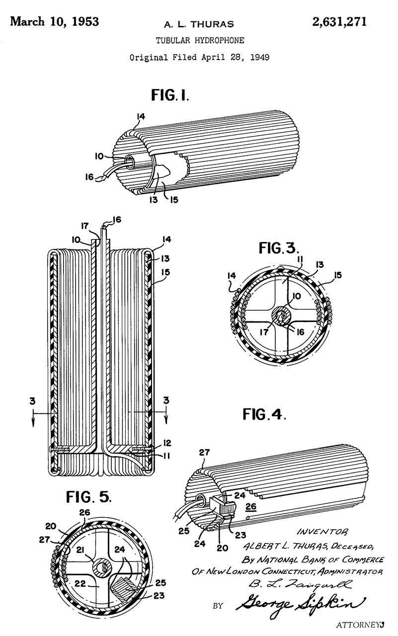
2631271 Tubular hydrophone, A.L. Thuras (New London, CT), Sec of Navy, Mar 10, 1953, 367/168 - CRT-1
2641751 Hydrophone casing, Bernier Jr Hector F, Mason Russell I, Ripken John F, Filed: May 11, 1944, Pub: Jun 9, 1953, 367/173 - stowing hydrophone cable and stowing hydrophone in sonobuoy.
2749532 Hydrophone, Harris Wilbur T, Harris Transducer Corp, Jun 5, 1956, 367/168, 310/26 - Nickel sheet metal cylinder similar to CRT-1
2886794 Microphone, Filed: Sep 11, 1943, Granted: May 12, 1959, 367/168, 310/26, 114/25, 367/157, 381/190 - magnetostrictive
2979690Dual magnetostrictive hydrophone, Reginald A Hackley, Mar 29, 1946, Apr 11, 1961 (SECRET for 15 years),
367/156, 333/201, 181/165, 116/DIG.180, 381/427, 381/162, 310/26
3509523 Helical-wound magnetostrictive line hydrophone, Parker David E, Prentice Winslow W, Us Navy, Apr 28, 1970, 367/168
" ...can be economically fabricated in a continuous manner to provide any desired length."
3059217 Transducer-hull for underwater use, Boswell Vance F, Oct 16, 1962, Clevite Corp, 367/173, 310/26, 114/20.1 - made of Nickel sheet metal very similar to the CRT-1
Magnetostriction (Wiki) -
The Maritime web page says this is how it works.
"...a cylindrical magnetostriction unit that is wound on a nickel shell. Its construction permits the storing of the cable inside the hollow shell and effects a reduction in length of about 4 inches compared with earlier models."
2631271 Tubular hydrophone, A.L. Thuras (New London, CT), Sec of Navy, Mar 10, 1953, 367/168 - CRT-1 Fig 5 Tags at top of Antenna
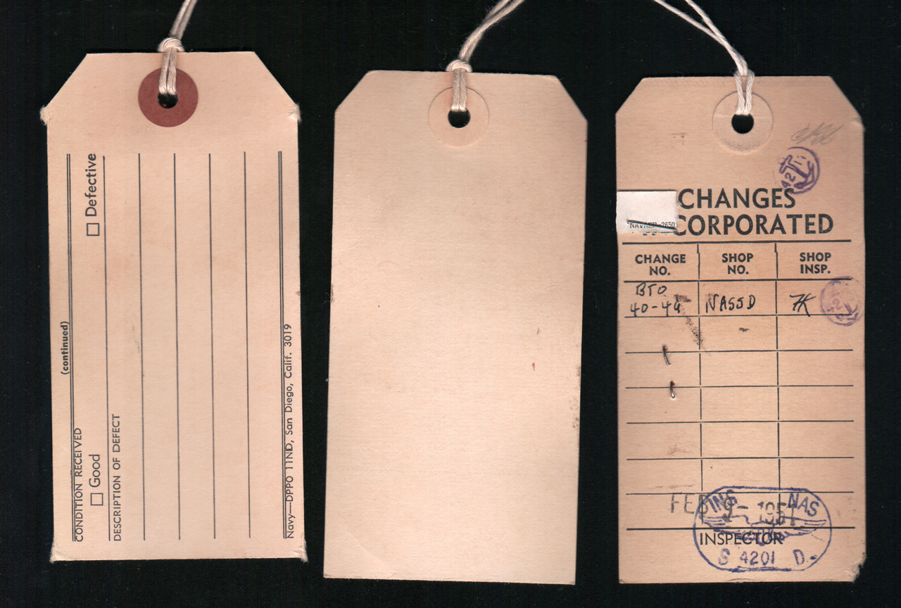
Electronics Follow up and evaluation Tag (not filled in)
T.O. 49.49
REQUIRE
2 each BA-51 (2 * 67.5V = 135 V B+)
and
4 each BA-30 (parallel connection 1.5V filament)
Ready for Issue Tag
Part No. AN/CRT-1B
Nomenclature: Transmitter
Stock No. R-16-T-9171
BU or Serial No. 2805 CEX
Fig 6
(not filled in)
(Blank)
(paper under staple) Nav??p 2650
Changes Incorporated
Change No. B50 40-49
Shop No. NASSD
Shop Insp. HK
Stamps 42(anchor)11, 42(anchor)30
Fig 7 Schematic of Transmitter
The circuit shows an input jack and no DC bias on the transducer, so it may be working without any electrical bias, but there is a permanent magnet to provide the bias.
Fig 7 Electronics assembly
RCA jack in lower left is hydrophone input
Fig 8 Electronics assembly
135 Volt B Battery above A battery
1.5 Volt A Battery at bottom (maybe 4 "D" cells?
Fig 9 Close-up Electronics assembly
marked:
T 1B/CRT-1
Clear plastic cylinder removed
Chassis plate is shock mounted
Tube on left is marked 3A4
RF Oscillator & Final Amp
Fig 10 Close-up Electronics assembly
Clear plastic cylinder removed
Tube on right is marked 1L4
ARR-3 used in aircraft. Powered by 24 VDC. The 12 Volt filament tubes are paired so filaments are powered by 24 VDC. A "rotary transformer" supplies the B+.
Versions
Sonobuoy
Frequency
Receiver
CRT-1
?
?
CRT-1A
67.7 to 71.7
R-2/AAR-3
CRT-1B
62.9 to 66.9
?
Sonobuoy Receivers
R-2/ARR-3
VHF Low1 Sonobuoy Receiver; used with AN/CRT-1, 67.7 to 71.7 Mc/s. R-2A/ARR-3
VHF Low2 Sonobuoy Receiver; used with AN/CRT-1A and AN/CRT-1B, 62.9 to 71.7 Mc/s
R-156/ARR-16
VHF Low
VHF Sonobuoy Receiver; used with AN/CRT-1, 62.8 to 72.1 MC (Fair radio 6 Jun 1963 ad)
CRT-4 mentioned in CO-AN 16-30URM1-2-M manual for the URM-1 sound test box
R-332/ARR-21
VHF Hi SSQ-2 (jproc.ca)
R-316/ARR-26
VHF Hi
Sonobuoy/Bathythermograph Receiver; manufactured by Texas Instruments; used in A-1, P-2, P-5, S-2, Z-1, ZPK R-332/ARR-31
?
Sonobuoy Receiver; used in P2V-4, PBM-5S
Photo courtesy of Nico.
R-1170/ARR-52
VHF Hi
FM Sonobuoy Signal Receiver; used in P-2, P-3A, S-2, SH-2D, EC-121R "IGLOO WHITE" (Wiki, Sonobuoy\Ref 72)
SSQ-36 to SSQ-71
ARR-58
"
"Jezebel" Sonobuoy Signal Receiver; used in P-2, S-2, Z-1 ARR-72
" Sonobuoy Receiver; manufactured by Flightline and Japan Radio; used in P-3C, S-3, SH-60
SSQ-36 to SSQ-71
ARR-75
" Sonobuoy Receiver; 31 channels, manufactured by Flightline Electronics; used in P-3C, S-2G, SH-2G, SH-3H, YSH-3J, SH-60B
SSQ-36 to SSQ-71
ARR-76
" VHF Sonobuoy Receiver; manufactured by Resdel Eng.; used in P-3C, S-3
SSQ-36 to SSQ-71
R-2266
AM-6875
/ARR-78
S-3B MIL-R-85693 - 32 bit word digital interface, 99 RF channels,
ARR-84
" Sonobuoy Receiver; manufactured by Flightline Electronics; used in SH-2G, SH-60, P-3 ARR-502
" Sonobuoy Receiver; manufactured by Flightline Electronics, used in P-3B (for export), CP-140 (Canada) Frequency Plan
Figuring this out was only possible with the help of Van who has a copy of the CRT-1A manual dated 1 May, 1944, CO-AN 08-30CRT1-2. The clue was the different but adjacent frequency coverage of the CRT-1A compared to the CRT-1B.
Frequency range: 62.8 to 72.1 MHz (1963 Fair Radio ad)
The pdf description below has this:
Frequency range
AN/CRT-1A (black band) 67.7 to 71.1 Mc/s where there are 6 channels.
AN/CRT-1B (white band) 62.9 to 66.9 Mc/s where there are 6 channels.
The dial shown in Ref 4 above is for the R-2A/ARR-3. Note the photo of the ARR-3 tuning window in Ref 4 shows the colors Green Purple Orange corresponding to 66.9 (Yellow background), 67.7 & 68.5 Mc/s (Black background).
All the channels seem to be spaced 0.8 Mc/s. This is my best guess (10 May 2021).
Whole table is frequency plan for the ARR-3B based on the Navships 94200
The bottom half would be for the ARR-3 that only works with the CRT-1.
Table updated 2021 May 18 based on Navships 94200.
Chan
Color
MHz
Black
CRT-1A
CRT-1B
Green
Yellow
Red
Blue
Orange
Purple
71.7
70.9
70.1
69.3
68.5
67.7
Yellow
CRT-1
Green
Yellow
Red
Blue
Orange
Purple
66.9
66.1
65.3
64.5
63.7
62.9
Photos
ARR-3 Photos and information supplied by Michael, VK4ZKT
Fig ARR-3 #1 Front with 1629 Magic-Eye tube.
First made by Freed Radio, New York City.
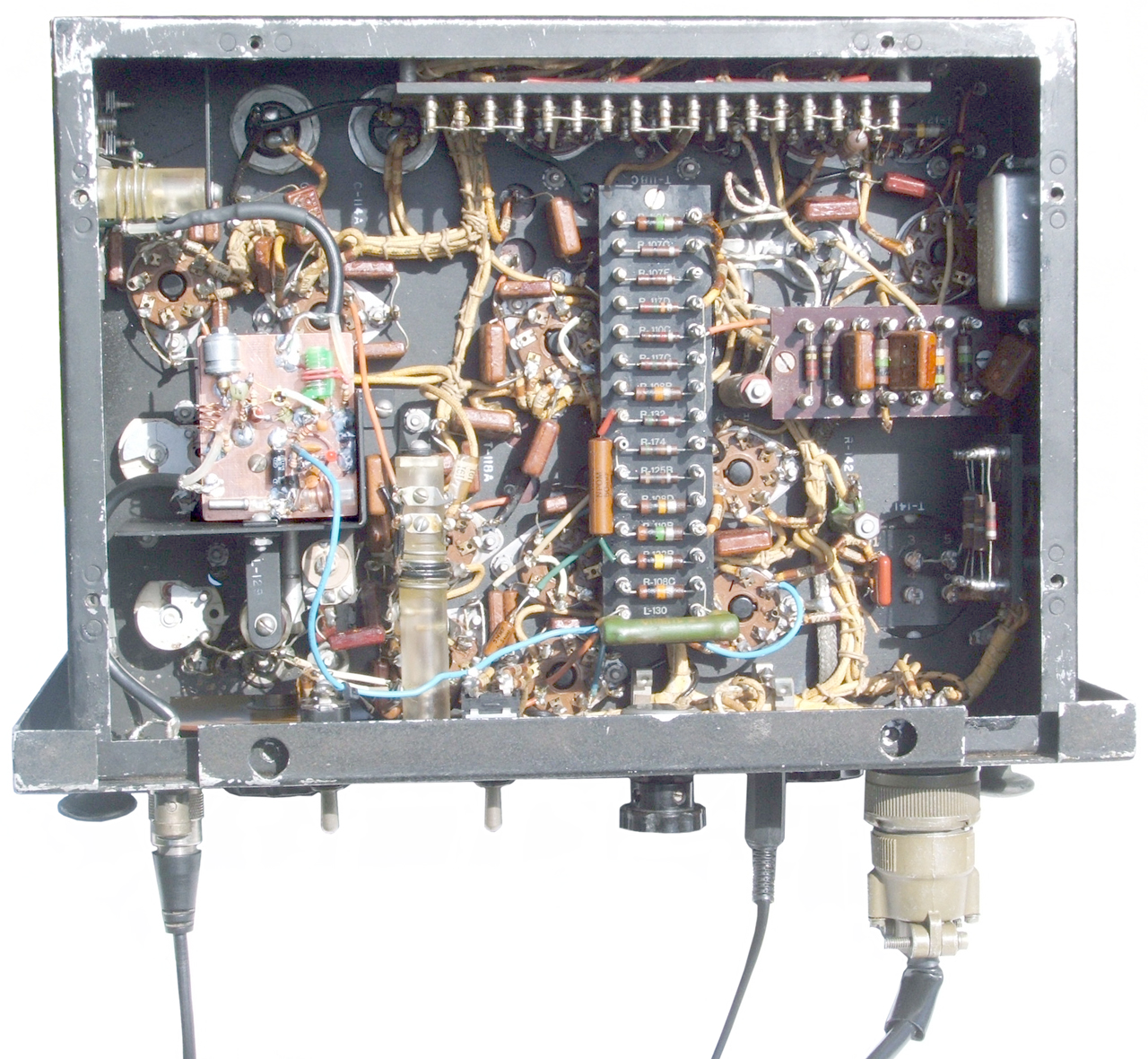
Fig ARR-3 #2 Back Inside
Fig ARR-3 #3 Bottom
FET converter PCB allows reception of FM broadcast
Description (pdf) with schematic
2017 June 30 from eBay UK seller jet-art-aviation
JetArt web page
See the Sonobuoy web page MAD section.
Also search on the Torpedoes web page.
Mk24 Ref 1 Sonobuoy Ref 39, pg 36:
"The project was headed by Western Electric;
the homing system effort was centered at the Bell Telephone Laboratories and the Harvard Underwater Sound Laboratory.
Engineering development of the torpedo, Mine Mk 24 (mine being a misnomer for security reasons), was assigned to Western Electric Co., Kearney, N.J. and the General Electric (G.E.) Engineering and Consulting Laboratories, Schenectady, N.Y.
Mk24 Ref 2 US Navy Torpedoes, Frederick J Milford: Part Four: WW II development of homing torpedoes 1940-1946 (archive.org)z
Mk 24 Passive homing General layout pg 37, Fig 16
Mk 32 Active homing General layout pg 39, Fig 17
Mk24 Ref 3 Summary Technical Report of Division 6, NDRC, Vol. 22, Acoustic Torpedoes, 1946 (DTIC_AD0221612.pdf), 185 pgs,"In response to the Navy request NDRC convened a meeting at Harvard on 10 December 1941. Two weeks later at a second meeting the following requirements were outlined:
         size to fit 1000 lb bomb rack, i.e.,smaller than 19" x 90"
         droppable from 200 to 300 ft at about 120 k.
         electric propulsion using lead acid storage battery
         12 knots for 5 to 15 minutes
         100 lb high explosive charge
         acoustic homing with greatest possible range
While the HUSL system was not selected for the Mk.32 torpedo, many of its features were incorporated into the Penn State Ordnance Research Laboratory Project 4 system which was the basis for the very successful Mk.37 torpedo.
While learning about SOSUS (Wiki) and Frederick Hunt (Wiki) I found Hunt's patent for the Navy describing how to wind the Nickel core for the CRT-1 hydrophone. One of the co-inventors on patent 2666192 turns out to hold many patents for the Mk 24 Mine (Wiki) which is an acoustic homing torpedo. The other names on that patent are:
Frederick V Hunt Schuck Oscar Hugo Charles R Rutherford Hathaway Jarrett Lewis Jr Arthur Nelson Butz
Patents by Cecil K Stedman:
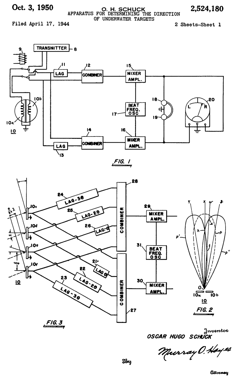
2528180 Apparatus for determining the direction of underwater targets, Schuck Oscar Hugo, App: 1944-04-17, W.W.II, Pub: 1950-10-03, - cited by 3021807.
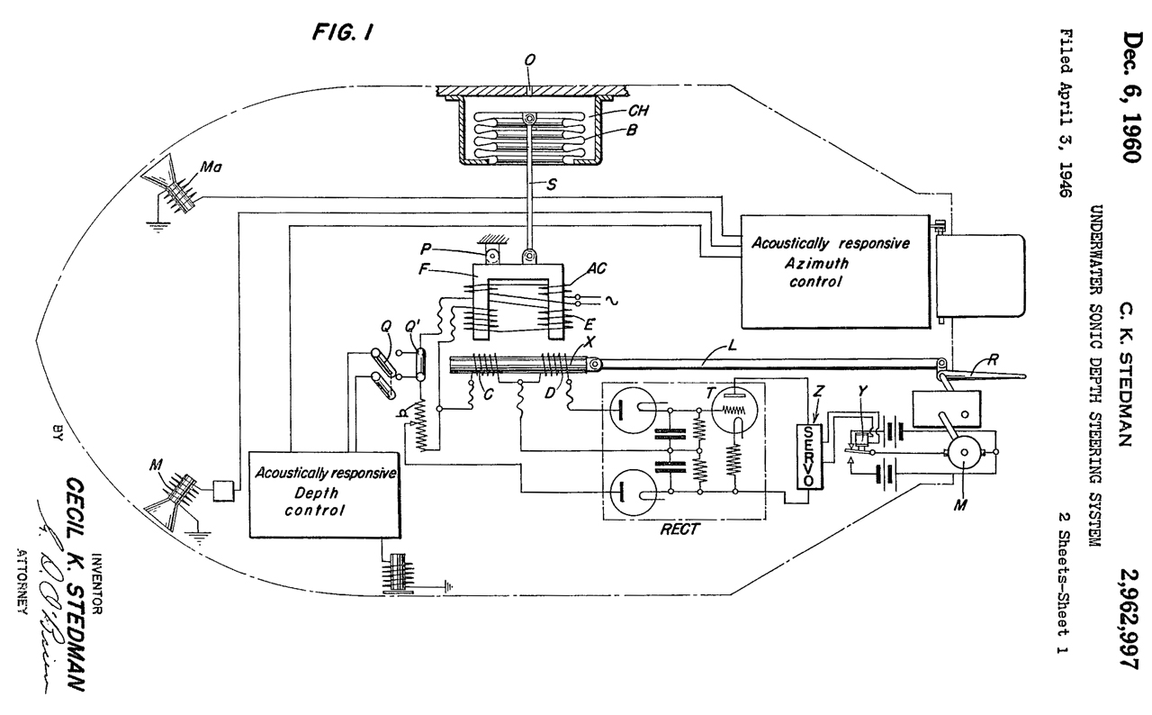
2962997 Underwater sonic depth steering system, Cecil K Stedman, Navy, App: 1946-04-03, TOP SECRET, Pub: 1960-12-06, -
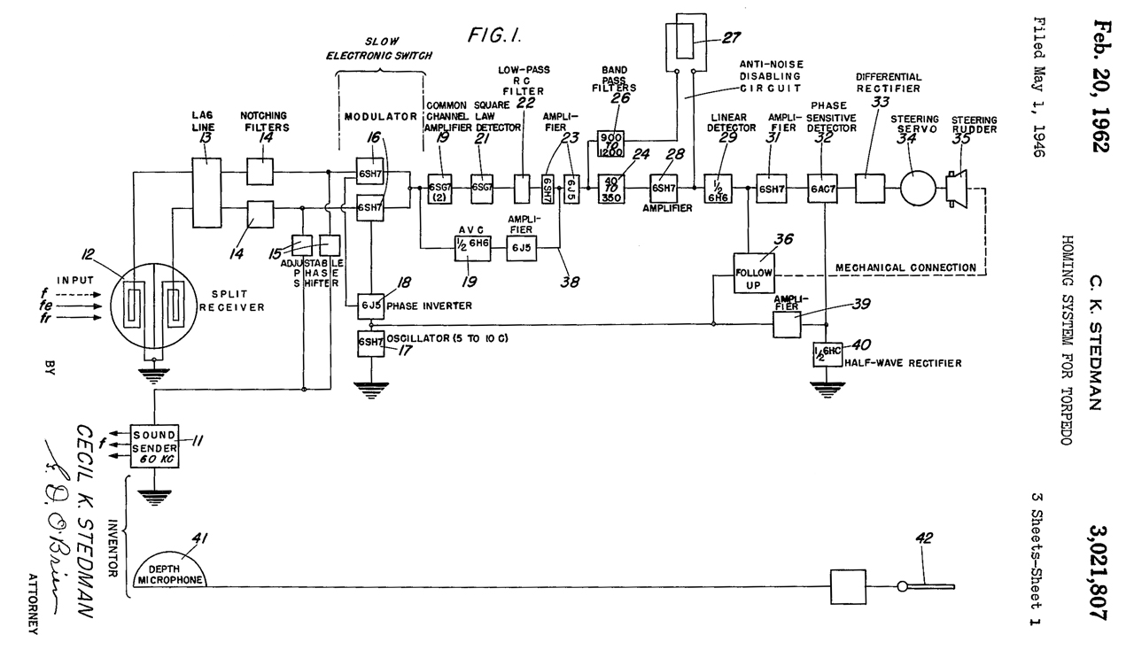
3021807 Homing system for torpedo, Cecil K Stedman, Navy, App: 1946-05-01, TOP SECRET, Pub: 1962-02-20, - a 60 kHz active SONAR homing torpedo. It ignores the self noise of the torpedo and only looks for the Doppler offsets from the 60 KHz ping. This would be a way to get around the problem of self noise. Note the schematic coil symbols (12, 27) are the coils wound around a magnetostrictive hydrophone.
This is probably the Mk 37 active acoustic homing torpedo. See General layout above for the Mk 32 proposal from HUSL.
This is covered in Mk24 Ref 3 Ch 19 Harvard Underwater Sound Laboratory N0181 System"
1336497 receiver mounting for submarine signals - through hull microphone Apr 13 1920, 381/177; 381/412
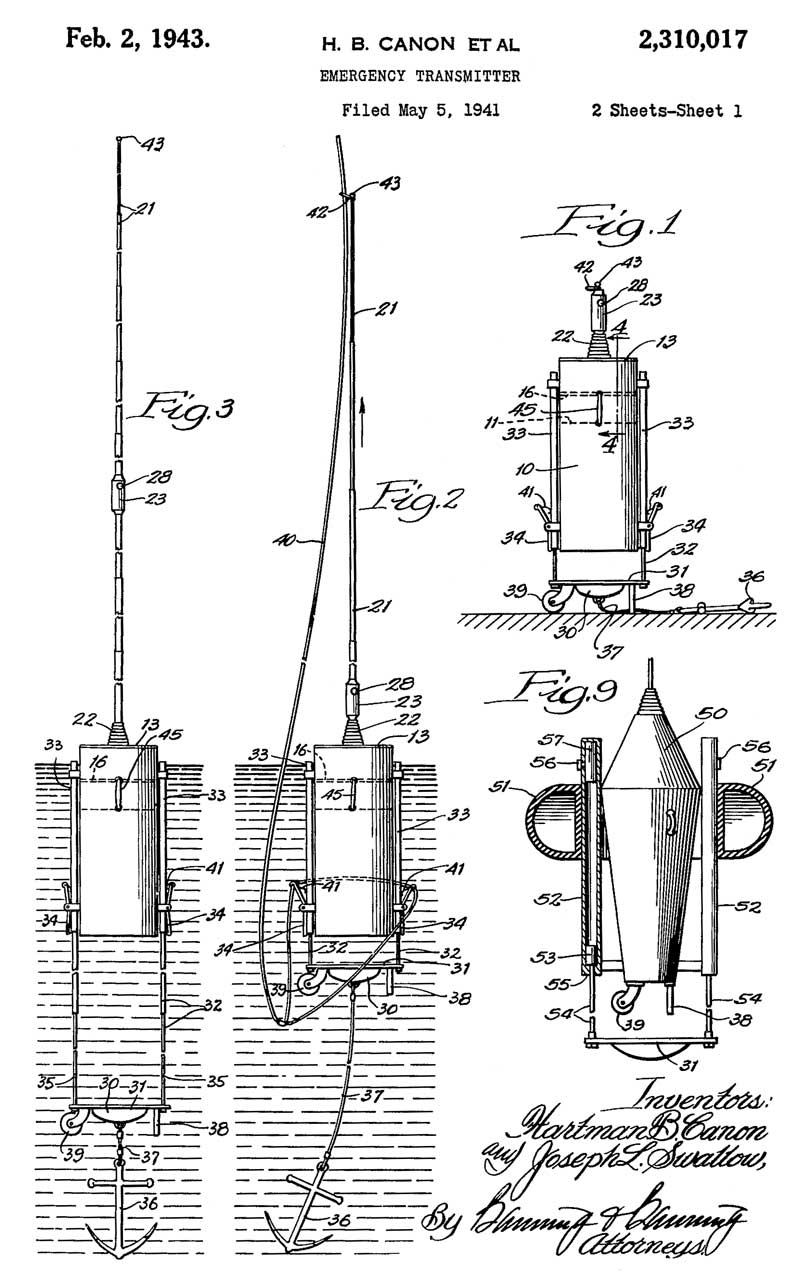
2310017 Emergency transmitter, Hartman B Canon, Joseph L Swallow, Gard Well Co, Wells-Gardner, App: 1941-05-05, W.W.II, Pub: 1943-02-02, -
While NOT the CRT-1, there are some similarities in construction.
Ref 1. Aircraft versus Submarine in two world wars by Dr. Alfred Price, 2004 (Price wrote Instruments of Darkness about ECM)
Ref 2. Scientists Against Time, James Phinney Baxter, 3rd Ed, 1946 - 1952 (Wiki)
Ref 3 YouTube: Navy Depth Charge Demonstration (1946) 24/10/1946. FILM ID:2347.03 - Really about Sonobuoys and probably the CRT-1. "Various tactical situations require different procedures and exact patterns. Only by learning these and adhering to them can the full effectiveness of sonobuoys be realized".
Ref 4. The Evolution of the Sonobuoy from World War II to the Cold War, Holler, Jan 2014. (alternate source.pdf)
Ref 5. Aircraft Versus Submarine in Two World Wars (1 & 2), Dr. Alfred Price, 2004 - has some new details on the CRT-1 including capabilities.
Year
Model
Audio
RF MHz
1942
CRT-1
300 - 8,000
1944
CRT-1A
100 - 10,000
67.7 to 71.7
CRT-1B
62.9 to 66.9 1954
SSQ-1
15,000 - 17,000
VHF Hi? 1956
SSQ-2B
VHF Hi
1957
SSQ-23
100 - 3,000
VHF Hi 1960
SSQ-28
VHF Hi 1961
SSQ-15
26,000 - 38,000
VHF Hi 1965
SSQ-41
10 - 6,000
VHF Hi
SSQ-57
10 - 10,000
VHF Hi 1969
SSQ-53
10 - 3,000?
VHF Hi 1981
SSQ-77
VHF Hi
R-2A/ARR-3 Tuning Window
Radio Channels from Fig 3.
Color v. 0 to 100 Dial scale.
Fig 3
Fig 3 Window Close up
Ref_6. World Radio History - the archived documents are searchable.
Ref 7. NAVAIR 28-SSQ-500-1, Sonobuoy Instructional Manual, 1976 - SSQ-36 to 71, ARR-52A, -72, -75, and -76
Ref 8. Hunting German U-Boats with Sonobuoys in WWII, 21:01 -
Sonobuoy
Radiosonde
Outdoor Intrusion Detectors
GSQ-154
GSQ-160
Torpedoes, depth charges, mines and hedgehogs
Submarines
Maritime Museum: Expendable Radio Sonobuoy Training Records, 15P3: Manual for Expendable Radio Sono-buoy Training Records,
Richard Muller Physics Lecture 11 - Waves 1 - W.W.II underwater channel and the Roswell connection - origin of the term "Flying Saucer".
PRC68, Alphanumeric Index of web pages, Products for Sale, Brooke's Military Information
page created 17 Dec 2014