Macbeth Illuminometer
© Brooke Clarke 2014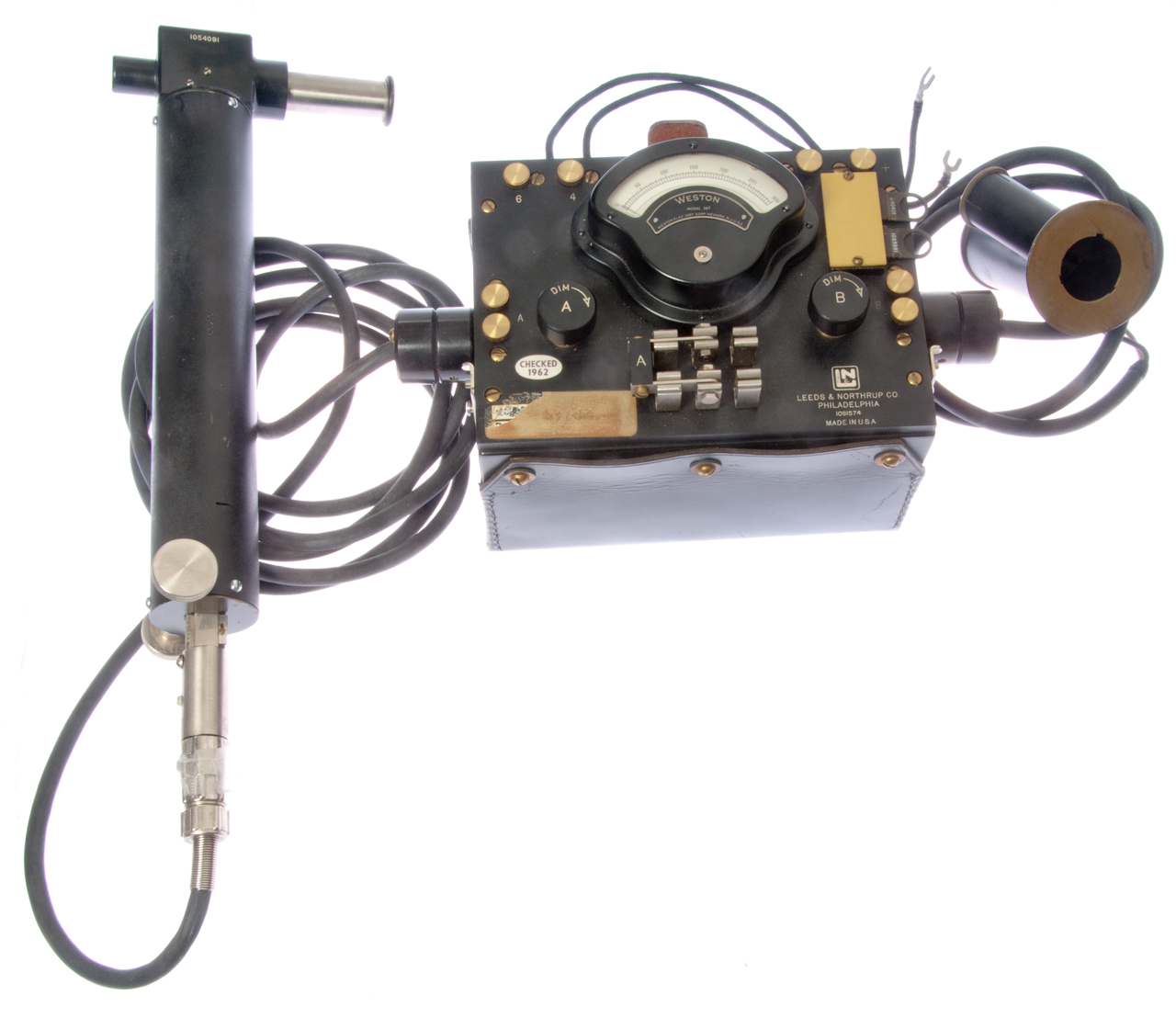
Description
Problem
Photos
Patents
Related
Links
Background
This instrument is based on a 1915 patent where the inventor is MacBeth and it was assigned to Leeds & Northrup and those are the names on the instruction booklet.
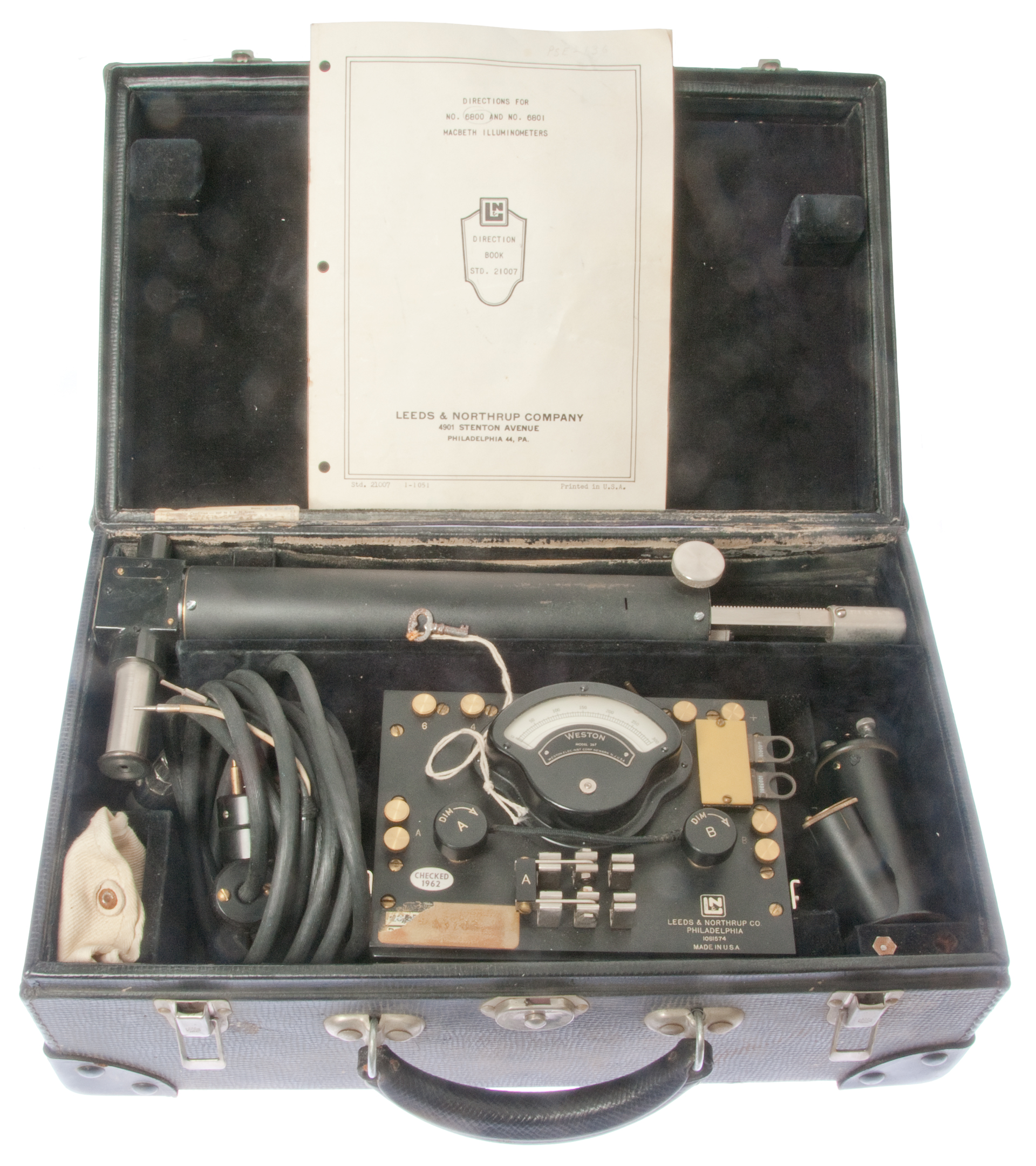
It comes in a custom suitcase with compartments fitted for the various parts.
This light meter works in a way that's very similar to the SEI Photometer. The SEI Photometer dates from 1935 and replaces the inverse square law (Wiki) rack and pinion slider with a variable graduated neutral density filter. Considering the method of operation and the physical similarity between these two light meters, I'd say this unit was the precursor to the SEI photometer.
Description
When I took photography classes at De Anza College the black and white class made use of The Zone System Manual by Minor White (Wiki) and for that class I got a Calumet 4x5 view camera and custom made a rectangular top plate for the Tiltall tripod to match the bottom rail mount of the camera. The Zone System Manual is a description of the method used by Ansel Adams and requires a spot light meter, so I got an SEI Photometer (See below: The SEI Photometer: A Legend Among Spot Meters). The spot in the center of the field of view changes brightness. There is a battery and a calibrated lamp along with an adjustable potentiometer. The pot is calibrated in light values so when the spot is the same brightness as the surrounding part of the scene you know the exposure for that spot.
The steps AFAICR were:
- Determine your film speed by making wedge exposures on the 3x5 sheet negative and processing the negative using the manufacturer's instructions. (You could come up with film speeds for "pushed" processing as well.)
- Determine the enlarger exposure for a given height of the head and paper. Here "black" is depends on the light transmission of a clear negative.
- Meter the scene and note the exposure required when you want to see some detail in the shadow and where you want to see some detail in a highlight. Note: Most "excellent" photos have some total black where you can not see detail and some highlights were there's also no detail. If the difference in exposure value between the shadow detail and highlight detail is within the EV range you can get with the film and paper you're using fine, but if not (this is most of the time) then you need to revisualize the final print and decide where you will have detail and where the detail will disapear into highlight or shadow.
- PS. When using a digital camera with RAW file output capability, like the Nikon D300s, and that offers 14 bits per color channel then Adobe Camera Raw allows "developing" the RAW file and part of that is capturing detail in the shadows using "fill light". Since a jpg file has 8 bits per color channel and the camera has 14 bits, the difference of 6 bits amounts to extending the dynamic range by 6 bits or 6 stops. That's a huge improvement.
This meter works on the same principle, but rather than change neutral density filters the distance between the lamp and the comparison target is changed using a rack and pinion where the rack has a logarithmic calibration. Note in both the SEI and the McBeth the lamp current is held at the reference value. The SEI uses a photocell to monitor the light output of the lamp and the McBeth uses lamp current, but has a reference lamp to calibration of the measuring lamp.
As the rack is moved it moves the lamp. The rack is calibrated from 1 to 25 foot candles. Using the inverse square law.
As the current is increased to the measurement lamp a ring of light surrounding the central dot brightens. Moving the rack out dims the ring of light and the apparent brightness of the central dot seems to change.
Problem
There is what appears to be an XLR connector on one of the cables that should mate with the end of the Illuminometer, but the plug is too big in diameter.
The connector on the cable (Fig 8) that feeds the Illuminometer is marked: Cannon and sure looks like an XLR. That implies that the XLR connector was invented prior to 1915 when the patent for this device was filed. I'm trying to find the XLR patent and also dimensions of the XLR mating interface diameter with tolerances. Let me know if you can help.
The sleeve that should accept the XLR plug has an ID that's too small or the plug is too large in diameter. The sleeve also has no pocket or groove to accept the XLR locking finger.
It turns out that a few minutes with a jeweler's flat file reduced the O.D. of the plug it fit.
Photos
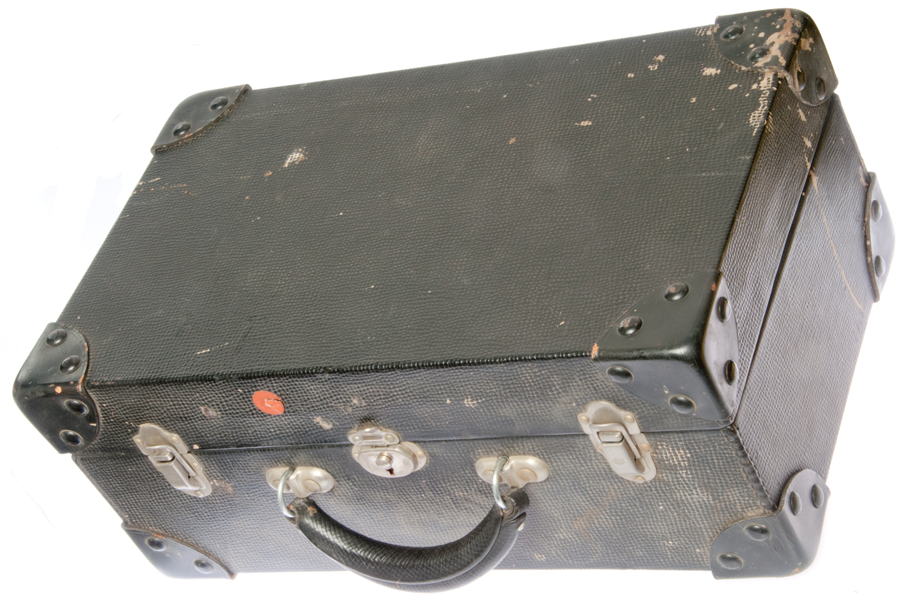
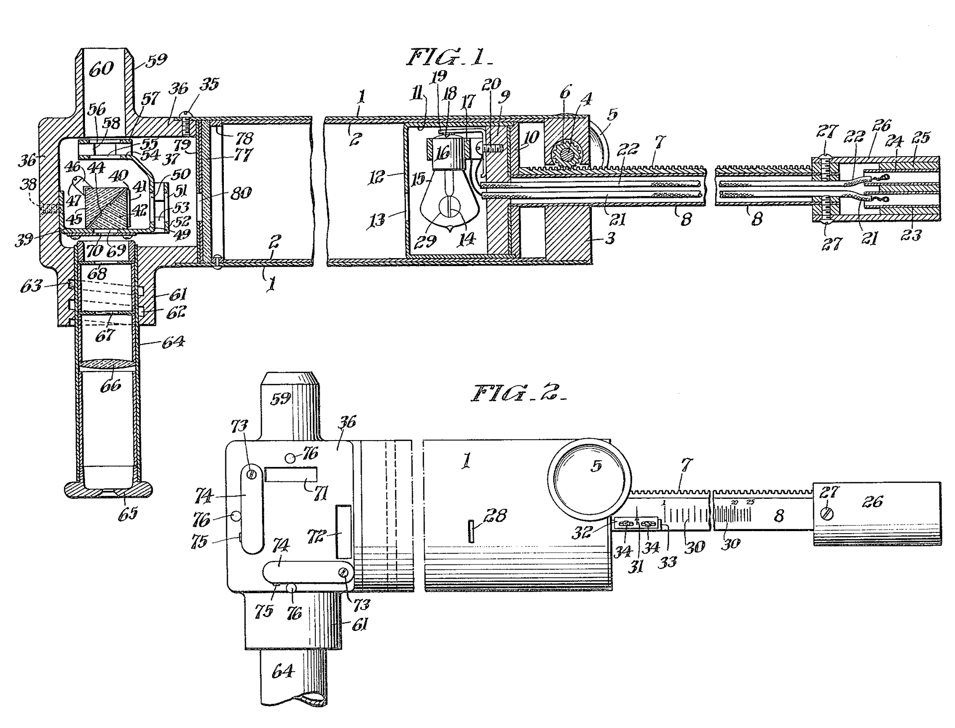
Fig 1 Suitcase 17" x 10.5" x 7.5", 17 pounds
Fig 2 Suitcase Opened.
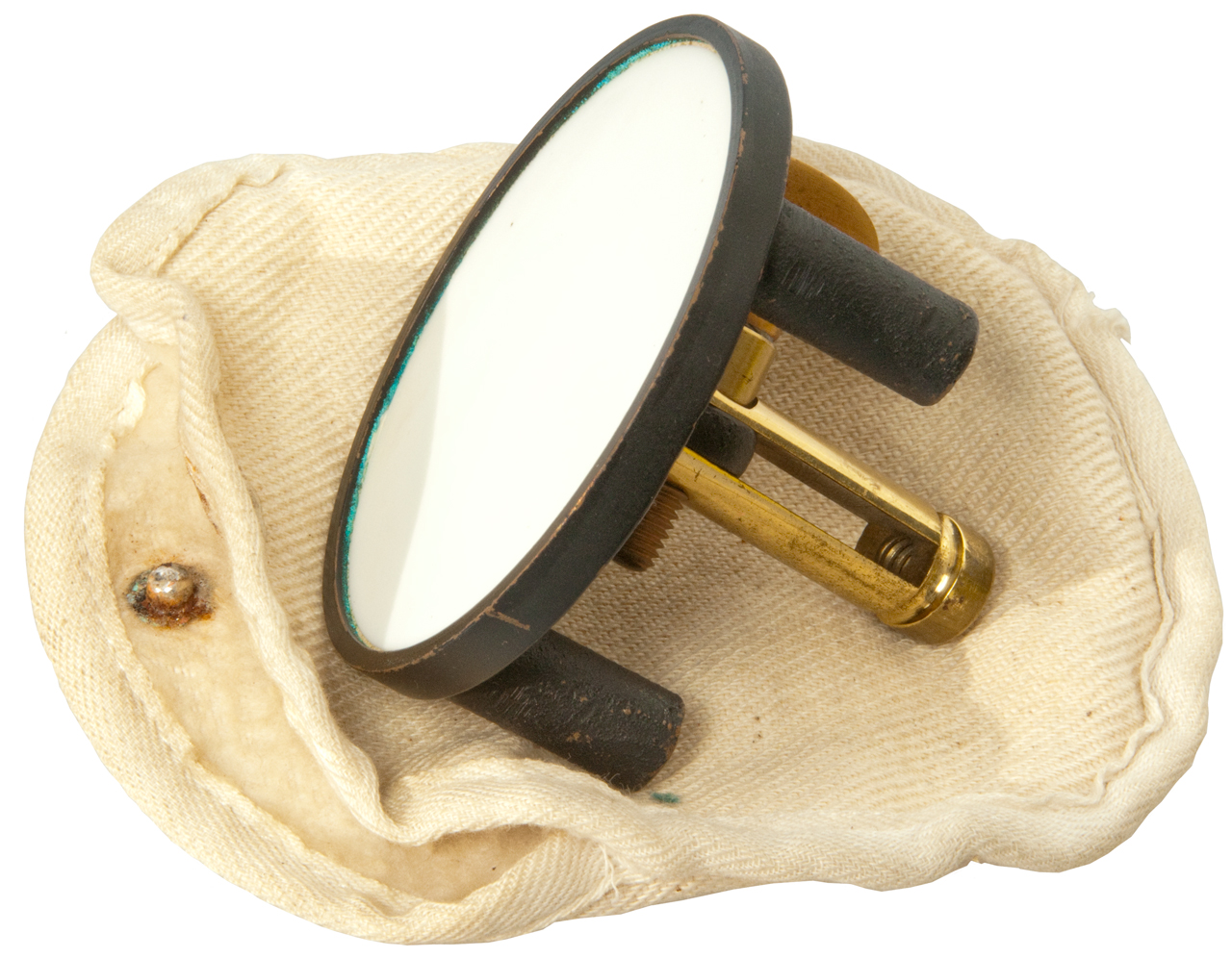
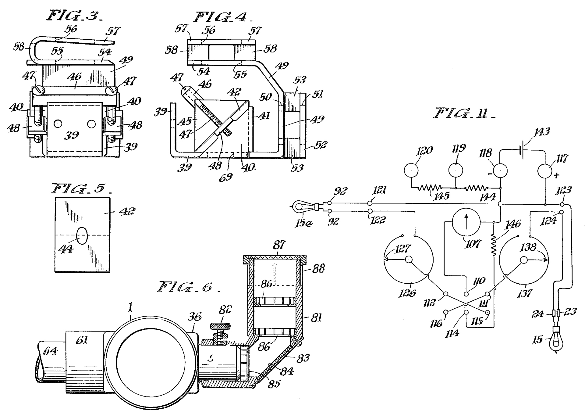
Fig 3. Target
Fig 4 Controller with 2 absorbing screens on right
Holds two No. 6 Dry Cells in leather case. The A-B DPDT knife switch selects either the measuring lamp or the reference lamp.
Weston 267 0 - 300 meter movement.
Leeds & Northrup Co. 1061574
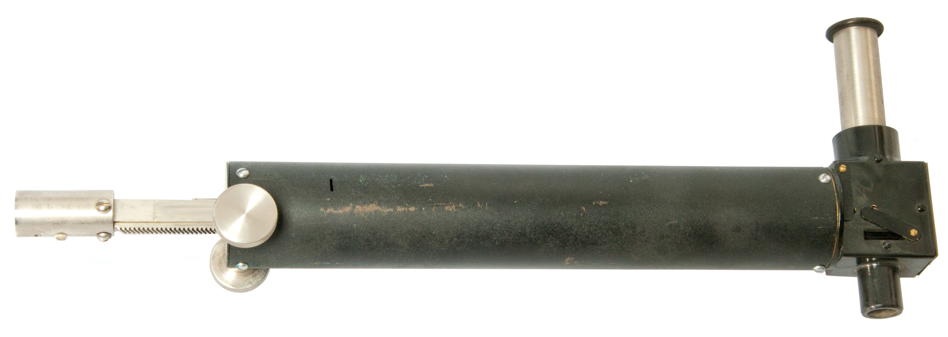
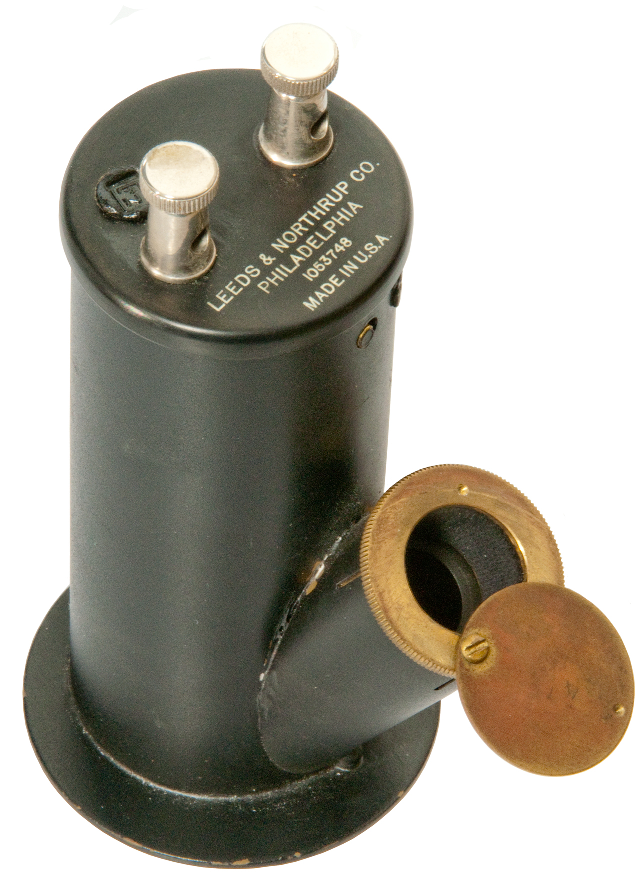
Fig 5 Illuminometer, Lummer-Brodhun cube (UoQ, GulpMatrix) at right end with slot for absorbing screens. Connects to Controller "B".
The helix focusing eyepiece is at the top right. The intensity
of the lamp is adjusted by rotating either of the pinion gears to
move the calibrated (1 fc to 25 fc) rack.
Lummer-Brodhun Ref: American Electrician 1901, Vol 13, pg 266 The choice of a photometer for central stations - compares Bunsen Sight Box with Lummer-BrodhunFig 6 Illuminometer note calibrated scale.
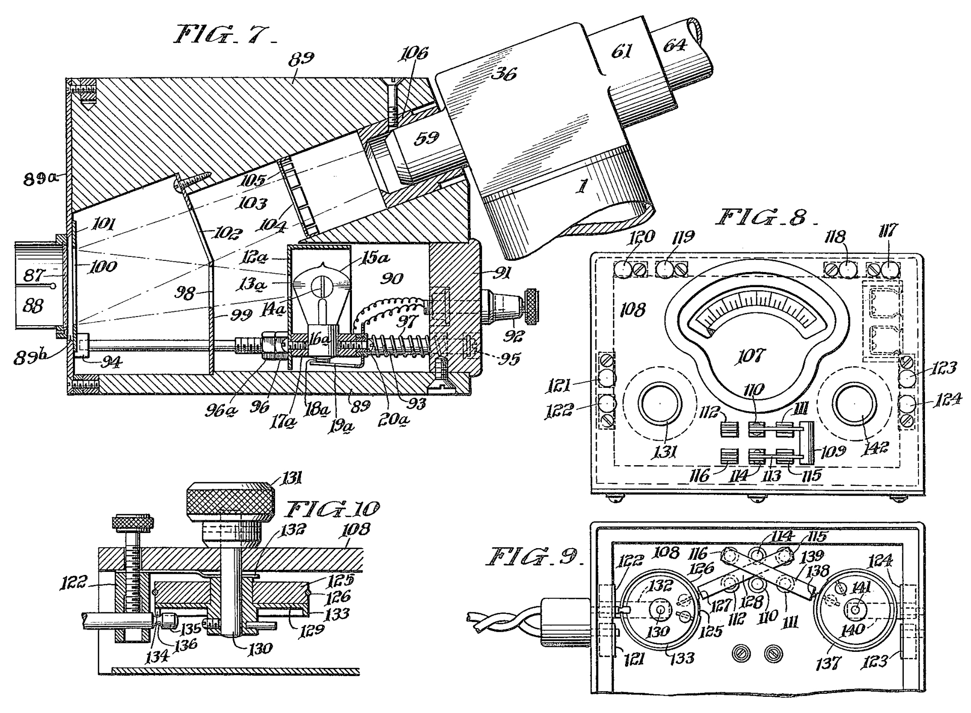
Fig 7 Reference Standard Light Source
Connects to the "A" binding posts on controller.
Fig 8 Cables
The cable on the right is used with the Reference lamp (fig 7) and the cable on the left with the Cannon (XLR?) connector connects to the measuring lamp. The O.D. of this connector
does NOT fit into the Illuminometer (Fig 5 & 6). So I think the Illuminometer was never used.
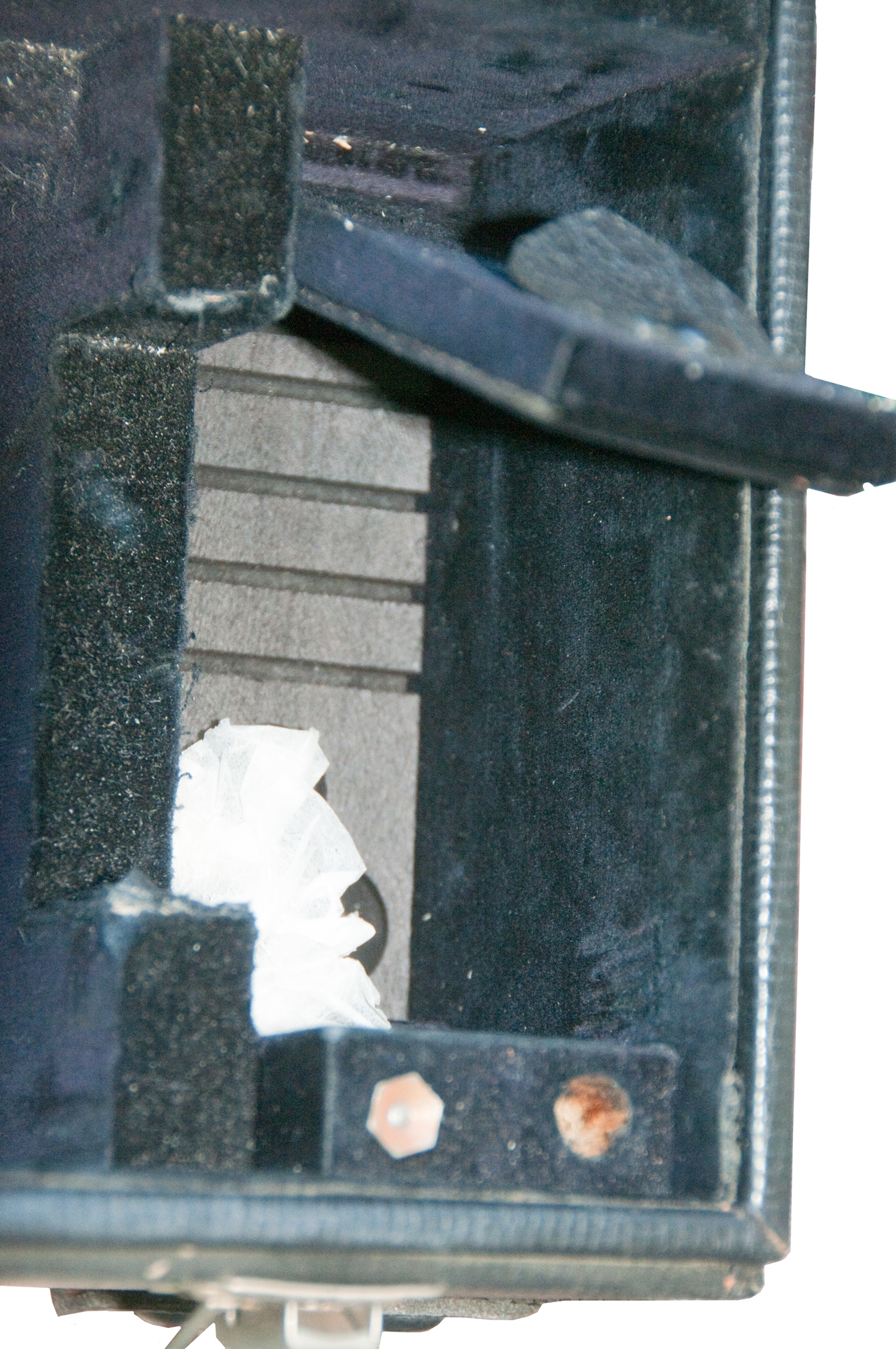
Fig 9 Lower right corner of case trap door and small
screwdriver and spare lamp.
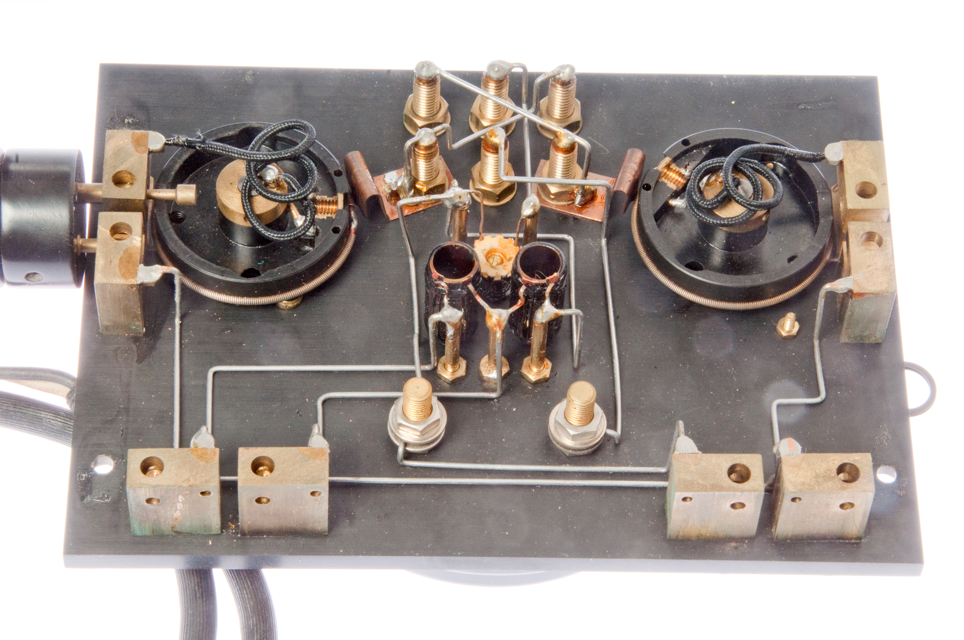
Fig 10 Back side of Controller showing notch in pot which
must be aligned with plug in order to insert plug.
Look at both the left and right pot positions after clicking on photo and if cursor is (+) click again. I could not insert plug until I opened it up to see the need to adjust pot first.
This was done so that you can not insert the plug if the pot is set at maximum current, which might blow the lamp if you are
using an external battery with more than 3 Volts. Patent
items 133, 134, 135,& 136)
Fig 11 (top of page) System with cables connected.
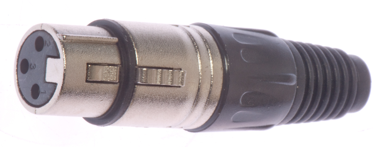
Fig 12 Modern XLR connector.
Note ridge for rotational alignment prevents it from fitting.