Capacitors
© Brooke Clarke 2010
Background
Examples of Bad Caps
Super Capacitors
Memory
Industrial/Commercial
Automotive Sound
Measuring the Capacity of a
Super Capacitor
Table
Variable
Related
Links
Background
These were purchased at test
subjects for the
ESR Micro combined
Effective Series Resistance and Capacitance meter. I was
going to put this data on that page but way too large so is here
as a separate page.
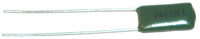
The first choice was to get leaded parts to allow insertion in the
ESR MIcro and the
SR715. Parts
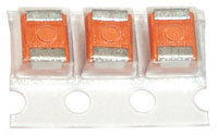
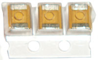
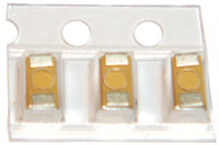
that are a few cents were ordered on tape at 100 each so in some
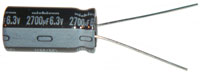
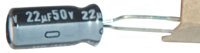
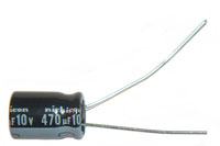
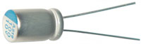
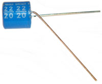
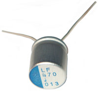
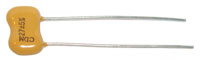
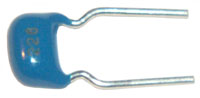
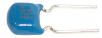
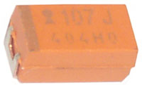
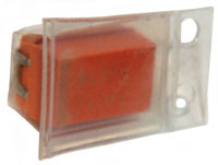
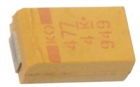
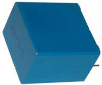
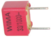
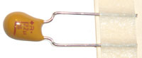
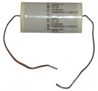
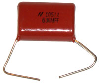
photos you will see the tape. The photos have been scaled so
they are all 200 pixels wide, so the scale factor varies a lot,
i.e. they are NOT shown in relative size.
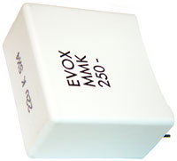
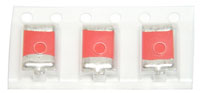
The photos will help ID different types of caps. More photos
on the
Capacitor Failure paragraph on
the Hints & Tips web page.
Wiki page
Capacitor
plague about the bad electrolytic caps (
Wiki)
made around 1999 but still being used up to about 2007 and failing
in 2010.
Examples of Bad Caps
These are related to using the
ESR-Cap meter.
This had nearly all the electrolytic caps bad. It's now
working great on the built-in whip antenna.
Oven Controller
See Hints and Tips: Cold Oven
Robertshaw
Controller in GE Electric Oven
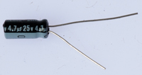
Two caps in the analog temperature control circuitry, both marked
4.7 uF 35 V, tested C: 000 ESR: ---. The interesting thing
is that the replacement caps, rated 4.7 uF 25 V, are larger.
This means the capacitors the factory used were faulty in that you
can't get that much capacitance in that small a package with that
voltage rating.
I didn't determine the working voltage of the 4-bit micro
controller but expect it runs on 5 volts. The LM324 op amp
might be running as high as 32 V, but I very much doubt it, +/- 15
would be the max expected, so getting 25 V replacement caps seems
to be conservative.
|
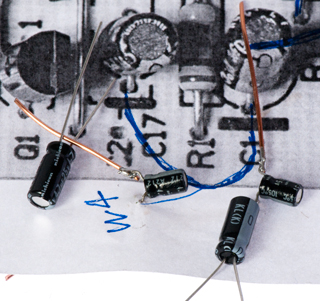
The bad C1 and C17 caps
were punched into a copy of the board photograph to keep
track of them and then bare wires were soldered on to
allow them to fit in the SR LCR meter or HP LCR
fixture. You can see that the new caps are much
bigger.
|
Cap
|
WVDC
|
dia
mm
|
height
mm
|
pitch
mm
|
Old
|
4.7
|
35
|
4
|
6
|
1.5
|
New
|
4.7
|
25
|
5
|
11
|
2
|
The height needs to be short in order to allow for the
relay board that's mounted directly above this board (see
the Hints and Tips web page).
The replacement parts were installed laying on their sides
out of general principles. But it turned out
it was required for vertical clearnace.
The volume of an electrylytic capacitor depends on both
the capacitance and on the working voltage and since the
new part has a lower working voltage there's a huge
difference in volume.
|
The SR 715 (1 kHz & 1V drive) shows the bad caps as about 20
nF (0.02 uF) not the 4.7 uF they should be and with a series
resistance of about 40 k Ohms. This is consistant with the
electrolyte evaporating. Note that total hours of use this
oven has seen is probably under 10 so the problem was not
heat. But the controler board (clock) is powered 24/7/365
minus the occasional power failure.
Super Capacitors
There are three general types of super capacitors (Wiki: Capacitor).
They are also known as Double Layer Capacitors (Wiki)
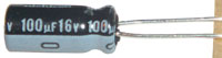
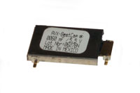
Memory Hold Up Super Caps
These typically have an internal resistance that's 10 or more
Ohms. Because of the high internal resistance they're
good for very low current applications, but can not be used
for powering motors or other high energy applications.
See 24 and 25 below.
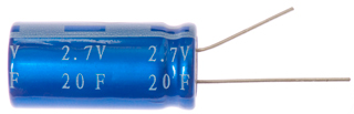
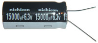
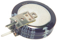
Commercial/Industrial Super Caps
These are typically single units and so have a breakdown
voltage under three volts.
Measuring (see below) a 20 Farad 2.7
Volt capacitor by setting the HP E3617A bench top power supply
for 2.5 Volts (below the 2.7 V max) and with the clip leads
shorted setting the current to 0.5 Amps.
Connecting the second clip lead when the clock is at the top
of a minute (23:32:00) and watching the voltage on the power
supply climb.
It gets to 2.0 volts at 23:33:25, i.e. after 85 seconds.
So the total Coulombs moved is I (Amp)* t (sec)= 0.5A * 85
seconds = 42.5 CoulC = Q / V = 42.5 Coul / 2 Volts = 21.25
Farads
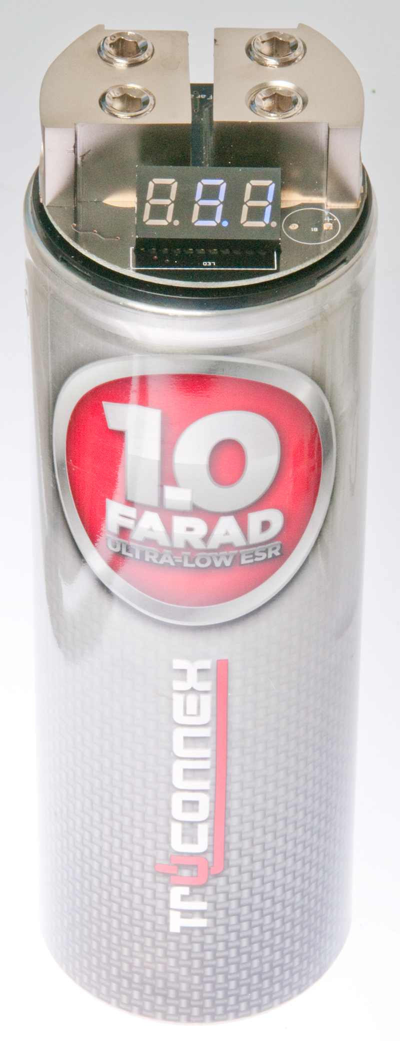
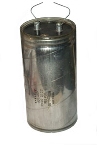
Automotive Audio Super Caps
These start at about 1 Farad and are rated for "12 Volt"
automotive electrical systems and so can be charged.
The built-in voltmeter shows Lo from about 5 volts to 8.34 Volts
then shows the voltage up to 15.9 Volts, and above that shows
Hi.
The meter draws 17 ma at 16 volts, which is a large part of 100
ma, which I'm using to measure the capacitance, so for measuring
the capacitance it's best to remove the meter.
It's probably also a good idea for automotive users to remove the
voltmeter so that the battery will hold it's charge for a longer
time. With the voltmeter connected the cap drains very
quickly, but without the meter the battery takes a few days to
discharge to 9 Volts. If the cap discharges too far it may
blow a fuse in an automotive application.

|
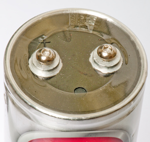
1 Farad Cap
with Voltmeter removed
|
|
|
Measuring the Capacity of a Super
Capacitor
The method is known as Coulomb (Wiki) counting
and is commonly used to measure battery State Of Charge (Wiki: SOC
Coulomb counting).
For example for the 1 Farad Truconnex super capacitor above I
started with the terminals shorted for a little while so the
voltage was zero.
Then setup an HP/Agilent E3617A bench top power supply for 16.0
Volts open circuit and with the leads shorted together set the
current to 100 mA.
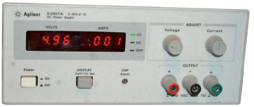
At the top of a minute I connected the power supply to the super
capacitor and watched the voltage meter on the supply climb up to
14 Volts and noted the time again (it was right at 2 minutes.
The number of coulombs delivered to the capacitor is 0.1 Amps *
120 Seconds = 12 coulombs
Note: The reason for using a current source rather than a
common power supply that's close to a constant voltage source is
that if a voltage source is used the current will be constantly
changing to reflect the voltage difference between the fixed
power supply voltage and the increasing capacitor voltage.
That makes it very hard to count the charge transfer (coulombs).
C = Q / V = 12 coul / 14 V = 0.857 Farad
Plotting in Excell the time vs. voltage and fitting a straight
line that goes through 0, 0 gives the following slope &
quality of fit:
Volts on the Y axis and Seconds on the X axis.
C = dQ / dV
dQ is the change in one second and since the current is 0.1 Amp
that's 0.1 coulomb.
dV is the slope of the line and that's 0.0776 so:
C = 0.1 / 0.0776 = 1.288 Farads
This may be a little more accurate than basing the capacitance
on a single measurement, like above.
There is a little curvature in the actual data compared to the
straight line, not sure why.
Next try this with a different current to see if it results in
a similar answer.

Table
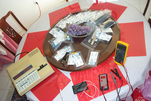
Tested in # order using all the
testers, then the next #. A Lazy Susan helped.
SR 715 at
left then counter clockwise
Micro ESR-Cap
meter,
EVB ESR (only) meter, Fluke
87
DMM
Note 1 The Fluke 87 has trouble
measuring the capacitance of parts in the pf range because it's
difficult to get a repeatable delta to zero the meter. A
plug in axial capacitor fixture might solve that problem.
Note 2 the Stanford Research 715 is fixtured for axial lead parts
only, SMT and supercaps do not fit.
Note 3 Multi Layer Ceramic Caps (MLCC) have frequency dependent
capacitance and series resistance on the SR 715.
Note 4 FRS is
Fair Radio Sales
Note 5 Leakage at 50 V (after soaking a minute) for
Cap30
Variable
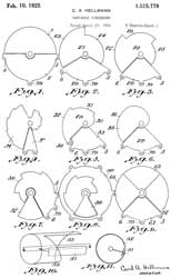
After a quick look at old patents I found this one where the
capacity is not a linear function of tuning shaft angle.
This is aimed at crystal radios.
A variable condenser used for transmitting must have extremely
low series resistance which is not required for crystal radio
use.
Looking for design info for rotor plates for linear AM radio
dial frequency.
|
 |
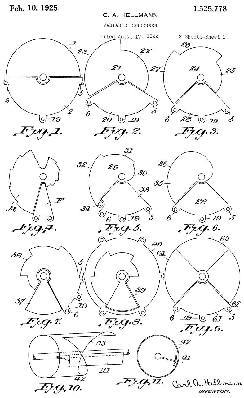
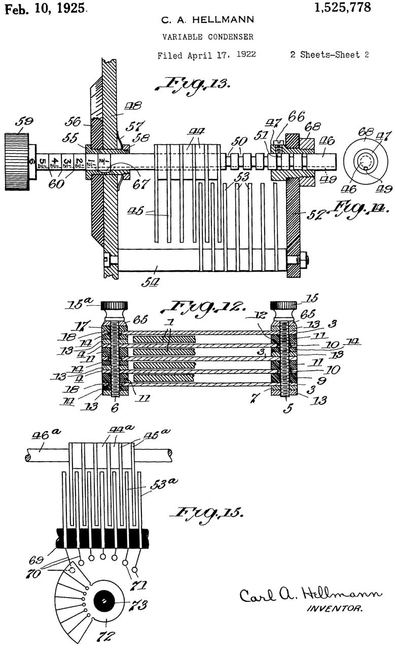
1525778
Variable condenser, Carl
A Hellmann, 1925-02-10, -
Fig 1. prior art linear & 180 deg rotation.
Fig 2. 240 deg useful range
Fig 3. 270 deg useful range
Fig 4. useful range of 360 deg * n/(n+1)
Fig 5 & 6. >180 deg range & non linear
Fig 7. rotor smaller angular extent than stator
Fig 8. like Fig 7 but different arrangement
Fig 9. >180 deg range
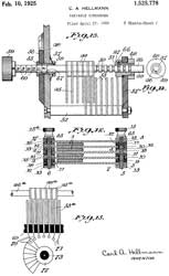
Fig 10 & 11. Cylindrical layout
Fig 12. movable dielectric w/fixed paltes
Fig 13. axial shift to change range
Fig 14. detail for Fig 13.
Fig 15. electrical detail for Fig 13.
1748345
Rotary variable condenser, Carl
A Hellmann, 1930-02-25, - similar.
|
|
|
1609006
Variable condenser, Clarence
D Tuska, CD
Tuska Co, 1926-11-30, -
bearing alignment
|
|
|
1709959
Variable condenser, John
W Simmons, RCA,
1929-04-23, -
rigid, fine adjustment,
|
|
|
2123050
Variable capacitor, Marwin
R Johnson, GE,
1938-07-05, -
slotted end plates to allow tweaking capacitance
curve.
|
1525778
Variable condenser, Carl
A Hellmann, 1925-02-10, -
Related
Links
Back to Brooke's Home,
Test Equipment, Products for Sale,
Military Information
web pages.
[an error occurred while processing this directive] Page created 11 Mar
2010.