I built one of these with the RS-232
option many decades ago. It a three channel HF receiver (5,
10 & 15 MHz) that receives either the U.S. or Hawaii WWVH time
and frequency broadcasts and displays the time to a tenth of a
second. It also has a discipline function that tweaks a 3.6
MHz crystal oscillator. So it could be called an HFDO, which
was available decades prior to any GPSDO like the Thunderbolt or Stanford Research PRS-10. The PST 1020 is a newer WWV/WWVH clock
which is faster to acquire the time.
There are other radio clocks that work
with the 60 kHz transmissions from WWVB/WWVBH that are often
called atomic clocks. While the HP 117
used the 60 kHz for a phase reference to determine the frequency
accuracy of a house standard, it was not used to discipline an
oscillator.
Operation
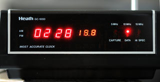
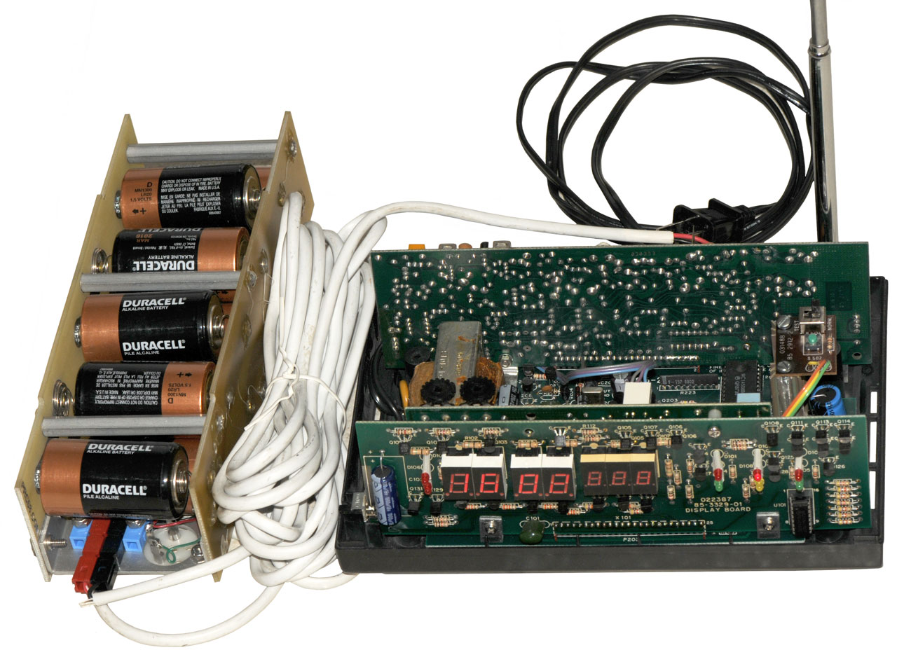
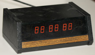
In the photo at the top of the page
the clock has just been powered up and is searching for the signal
using only the 53" whip antenna. When the speaker is turned
on you can hear the signal but the clock is not capturing the data
stream. Maybe the signal is too weak, or the receiver needs
to be aligned? It's also possible that the "8" digits are an
artifact of the camera exposure.
Manuals
1983 Manual p/n:595-3050? or p/n: GCA-1000-4? which includes
the Illustration Booklet that has the 1:1 scale PCB X-ray
views
Using the HP
8648A signal generator, with the 1E2 modulation option, it's
possible to generate an RF signal at 5, 10, or 20 MHz with either
100 or 1000 Hz modulation (and a choice of sine, square and other
100% AM waveform).
There is an audio file that could be used to AM modulate the
signal generator and should cause the clock to display the encoded
time. A better way would be to have a PIC micro controller
clock that outputs the 100 & 1000 time code data as audio to
feed the AM input of the sig gen.
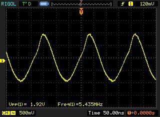
15 MHz RF Problem as received
The GC-1000 will respond to the 100 Hz modulation at 5 or 10 MHz
but not 15 MHz.
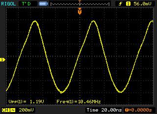
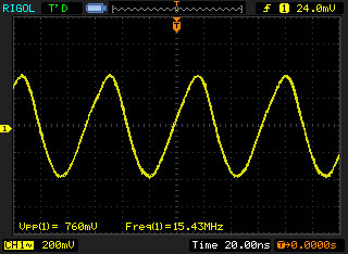
Using the Rigol scope on the LO
transistor, Q305 shows strong oscillation at 5 & 10 Mhz but
very weak oscillation at 15 MHz.
DC checks of the crystal selection circuitry does not show any
obvious problems.
Guessing that the problem might be: (1) crystal that's not too
active or (2) a weak Q305 (2N5770) transistor, (3) too close to
the bandwidth of the scope or some combination of these.
1 kHz Modulation
It does not respond to the 1000 Hz modulation at any RF frequency.
After swapping the two 567 tone decoder ICs (U402, U403), no tone
can be detected, even tried adjusting the pots.
BUT . . after returning them to the original locations
testing at 5 MHz showed the yellow data LED will light with 100 Hz
modulation and the capture LED with 1 kHz modulation. But
after trying 10 Mhz, no luck on either 100 or 1000 Hz modulation,
and coming back to 5 Mhz now only the 100 Hz tone decoder is
working.
At 5 Mhz after re-capping
the red AM LED is off at -132 dBm and on solid at -120 dBm (in
TEST mode). This required a slight tweak of the 1000 Hz pot.
This may be a better way to set the tone board pots than using the
internal calibration which probably has a strong audio signal.
Note: the green Capture LED has a very long time constant.
It takes 12 seconds after applying -110 dBm @ 5 MHz to turn on,
and 12 seconds to turn off after the RF is turned off.
At 10 Mhz after re-capping
it takes 15 seconds for the green Capture LED to turn on after
applying -100 dBm and just a few seconds to turn off. But
the turn off time seems to vary between a few seconds and almost a
minute.
At 15 Mhz after re-capping
it takes -90 dBm to get the red AM light to come on in TEST
mode. BUT, after switching to normal mode the green Capture
LED does not turn on.
100 Hz Modulation
At 5 Mhz the yellow data LED is out at -111 dBm, starts to flicker
at -103 dBm, and is on solid at -101 dBm.
At 5 Mhz After re-capping yellow data LED is
out at -111 dBm, and on solid at -109 dBm
At 10 Mhz it takes -50 dBm to turn on the yellow light, after
tweaking the 100 Hz pot at 15 Mhz it's now -109 dBm
At 15 Mhz it takes -30 dBm to turn on the yellow light, after
tweaking the 100 Hz pot -94 dBm.
IF Bandwidth
Measured by feeding a signal modulated with 100 Hz square wave at
enough power to have a solid yellow LED at nominal band center.
It looks like the LO crystals for 10 & 15 Mhz are not
centering the signal in the IF passband. This may mean that
it matters which channel is used to tweak the tone board
pots. For now I'll leave it with the 5 MHz channel well
centered since that's the channel that works best at night.
The total IF bandwidth should be the same for all the
channels. That it's not indicates that my method of using a
low flash rate for the yellow LED could be improved.
AGC
When it's back together use the HP 8648A
signal generator to vary the input power and watch:
the AGC voltage on Rx PCB at Q313E = connector X301-13
Tone Decoder PCB at U404C or connector X401-10
control bits on
Tone Decoder PCB at X401-12, X401-14, X401-16
If U404C output is OK then these must be OK
Receiver Board
Tests related to re-capping:
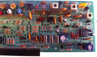
Photo just prior to testing
AGC electrolytic caps C348 & C359
Using the ESR-Cap meter to check the
electrolytic caps
Compare to new Capacitors Green
is after re-caping.
C#
Cap
uF
Nominal
ESR
Meas
ESR
Meas
Cap
C301
100
0.7
4 0.22
3.6 156
C348
4.7
na
20 4
3.58 4.9
C353
10
6
7 4.2
11.9 11.17
C354
10
6
58 4.2
6.85 9.29
C355
220
.5
3 0.4
122 211
C357
220
.5
1 1.1
180 177
C359
4.7
na
14.7 4.3
3.87 4.67
There was a question about
different versions of receiver board in relation to the
crystal loading capacitors.
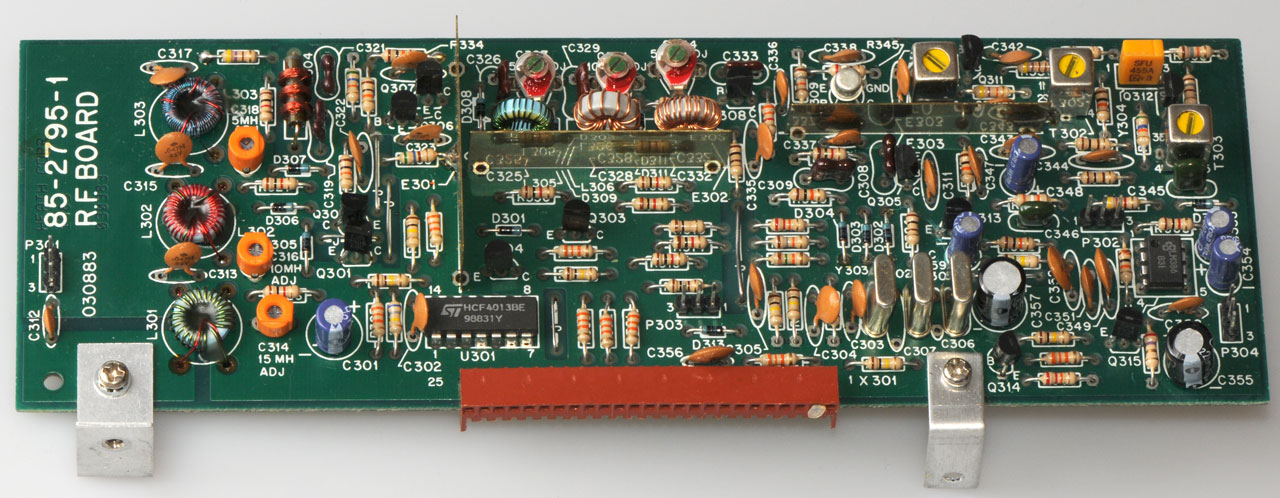
GC-1000 Receiver board p/n: 85-2795-1
You can see the three
crystal cans at the bottom center.
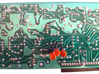
The loading caps have been installed on the back
There are three caps on the
back. They are not the correct values: Measured
Nominal Error 5,455,620
- 5,455,000 = 620 Hz 10,455,610 -
10,455,000 = 610 Hz 15,455,770 -
15,455,000 = 770 Hz
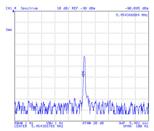
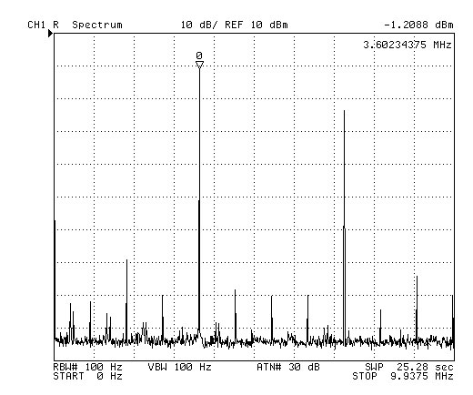
Local Oscillators
After some discussion about the loading caps for the three LO
crystals I checked my GC-1000 LO frequencies by connecting the
antenna and one of the rear panel BNC connectors ground to the
4395A in spectrum analyzer mode.
As long as the LO keeps the WWV carrier and sidebands inside the
IF bandwidth it should not matter. The tone frequency that's
output will depend only on the AM input signals.
Local Crystal Oscillator
schematic (click on image for larger version)
Q305 is an 2N5770
NPN Transistor
5.455 MHz LO Common anodes
of D302, D303 & D304, base of Q305
10.455 MHz LO Common anodes
of D302, D303 & D304, base of Q305
15.455 MHz LO Common anodes
of D302, D303 & D304, base of Q305
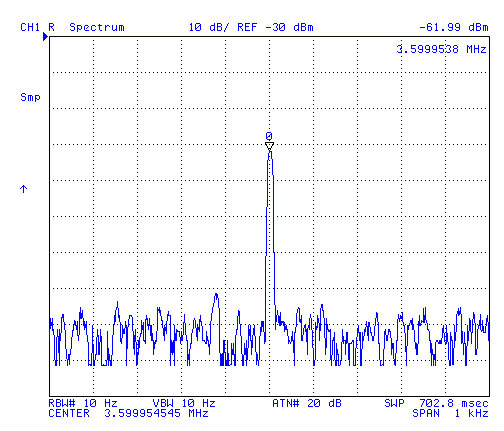
5.455 MHz LO
Between the time the signal was centered and the graphics
were saved the LO drifted a couple of Hz.
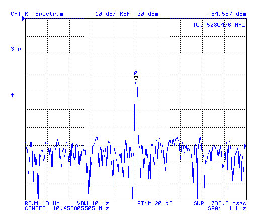
10.455 MHz LO
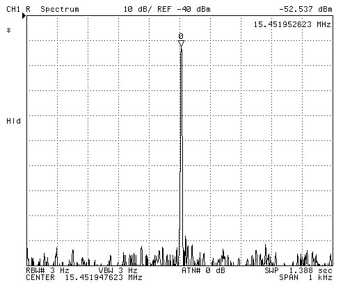
15.455 MHz LO as received
not present
after recapping OK
3.6 Mhz master Oscillator
Since the bandwidth of the 100 Hz PLL is narrow it may be that
using the built-in tone generator for tuning is a mistake.
It may be better to use a signal generator or an off the air
signal to peak the tone board decoders.
Micro Controller Upgrade
I think the micro controller is the
Mostek MK3870/22, i.e. it has 2048 bytes of ROM and 64 bytes of
RAM. The /44 part has twice the ROM so might be one way to
upgrade the uC.
Note the 3870 (either the clock or the RS-232 chip) use a 3.6 MHz
clock.
As received circa 1985 the 3.6 MHz
output was off by about 70 Hz using p/n 444-200. Heathkit
sent a new micro controller p/n 444-293 and that fixed the
problem, i.e. the 3.6 MHz output measured 3,600,000.0 Hz. I
wrote a letter to Heathkit
thanking them and pointing out that the DST/Standard Time switch
was in error.
A modern micro controller, like one of the PIC uCs could be
programmed with a better algorithm, like the PST 1020 or an even better one.
This could be done by making a PCB that would plug into the
existing U205 socket. Note the existing 3870 is a 40 pin IC
and the replacement PIC will probably need to have that many pins.
A Mil-max DIP
or SIP
header can be used to make the interconnection.
Pin
U203 Main
U401 RS-232
1
2
3.6 MHz in
3
Display
Digit
Mode
Mode
4
Display
Digit
Mode
Mode
5
Display
Digit
Mode
Mode
6
Display
Digit
Mode
Mode
Test Tone output (TP1-33k-TP2)
7
8
DIP sw
RS-232
Baud
9
DIP sw
RS-232
Baud
10
DIP sw
RS-232
Baud
11
DIP sw
Year
12
DIP sw
Year
13
DIP sw
Year
14
DIP sw
Year
15
DIP sw
Year
16
Display
Add
Osc Trim
Mode
17
Display
Add
Osc Trim
Mode
18
Display
Add
Osc Trim
Mode
19
Display
Add
Osc Trim
Mode
20
Ground
21
22
Display
Segment
23
Display
Segment
24
Display
Segment
25
Audio
on/off
26
Ground
(clock)
+5
(RS-232)
27
Test L
28
1 kHz
tone
29
/Stop
30
AGC
31
Band
Switch
32
Band
Switch
33
Band
Switch
RS-232
# Stop bits
34
Display
Segment
35
Display
Segment
36
Display
Segment
Ext Int
input
37
Display
Segment
RS-232
TxD (output)
38
100 Hz
tone
RS-232
RxD (input)
39
/Reset
40
+5
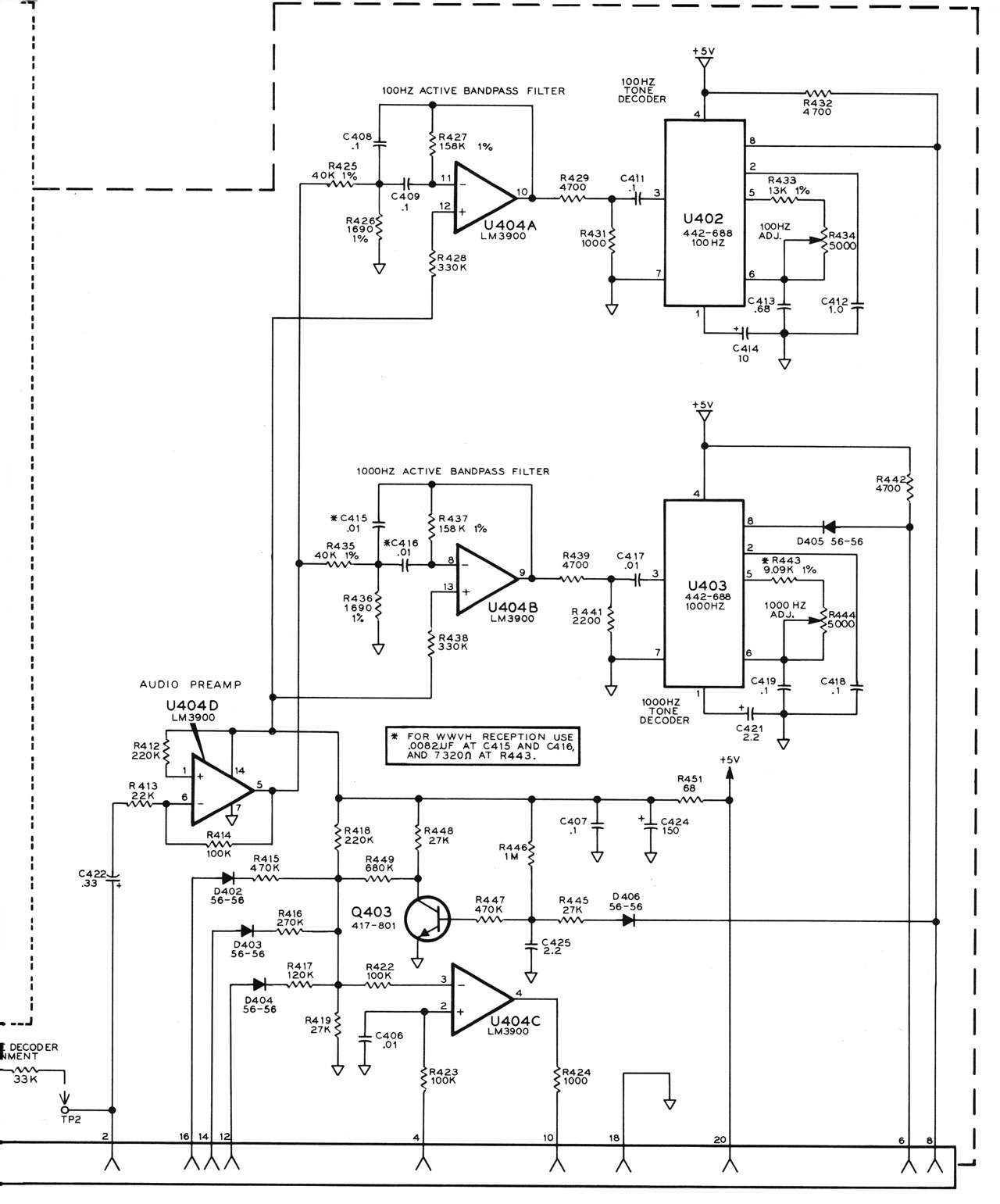
Tone Board
This clock has the optional RS-232
parts. At the top of the tone decoder board there's a 4-pin
header where one pin has been cut away and a pin is inserted into
the mating cable plug so they can only mate in one
orientation. The three wires are Ground, TxD and RxD.
The two pots at the upper right are the 1000 (or 1200) Hz and 100
Hz tone center frequency adjustments. The micro controller
used on this board is identical to the one on the main
board. Pin 26 determines if the uC is the main clock (gnd)
or the RS-232 interface and audio test tone generator (+5).
Note this board has the 444-293 micro controller,
i.e. the new one that's more accurate.
ESR-Cap measurements on
Tone Board electrolytic caps
C#
Application
Cap
uF
Nominal
ESR
Meas
ESR
Meas
Cap
C401
5V
PS
100
1
174 0.30
44 108
C404 Tant
U401
de-coup
3.3
na
3.6 4.5
68 70.5
C405
U401
de-coup
10
6
7.3 1.57
8.4 10.2
C412
U402
PLL
1
na
86 8.9
0.69 0.99
C414
U402
PLL
10
6
97 4.2
4.7 10.02
C421 Tant
U403
PLL
2.2
1
9.0 3.9
3.34 2.92
C422
U404D
Op
Amp
0.33
na
nr 29
nr 0.33
C424
R451
de-coup
150
1
30 0.37
41.5 217
C425 Tant
Q403
AGC
2.2
1
10.5 9.3
3.56 2.17
Note: My manual Tone Baord parts list (pg 21) is
missing C401 and C404.
Display Board
The display board plugs into the
motherboard and has the Tone Board connected to its back side.
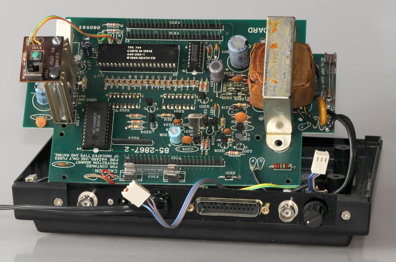
Motherboard
The micro controller is the newer 444-293 that's better
at disciplining the 3.6 MHz oscillator.
Electrolytic Caps
C#
Cap
uF
Nominal
ESR
Meas
ESR
Meas
Cap
C203
2200
0.1
0.7 0.04
1840 2920
C205
1000
0.2
2.2 0.12
1458 2414
C206
1000
0.2
2.1 0.13
458 1022
C208
220
0.5
9.5 0.15
165 222
C212
22
4
---- 0.85
0.05 24.9
C213
3.3
na
2.1 0.16
470 1018
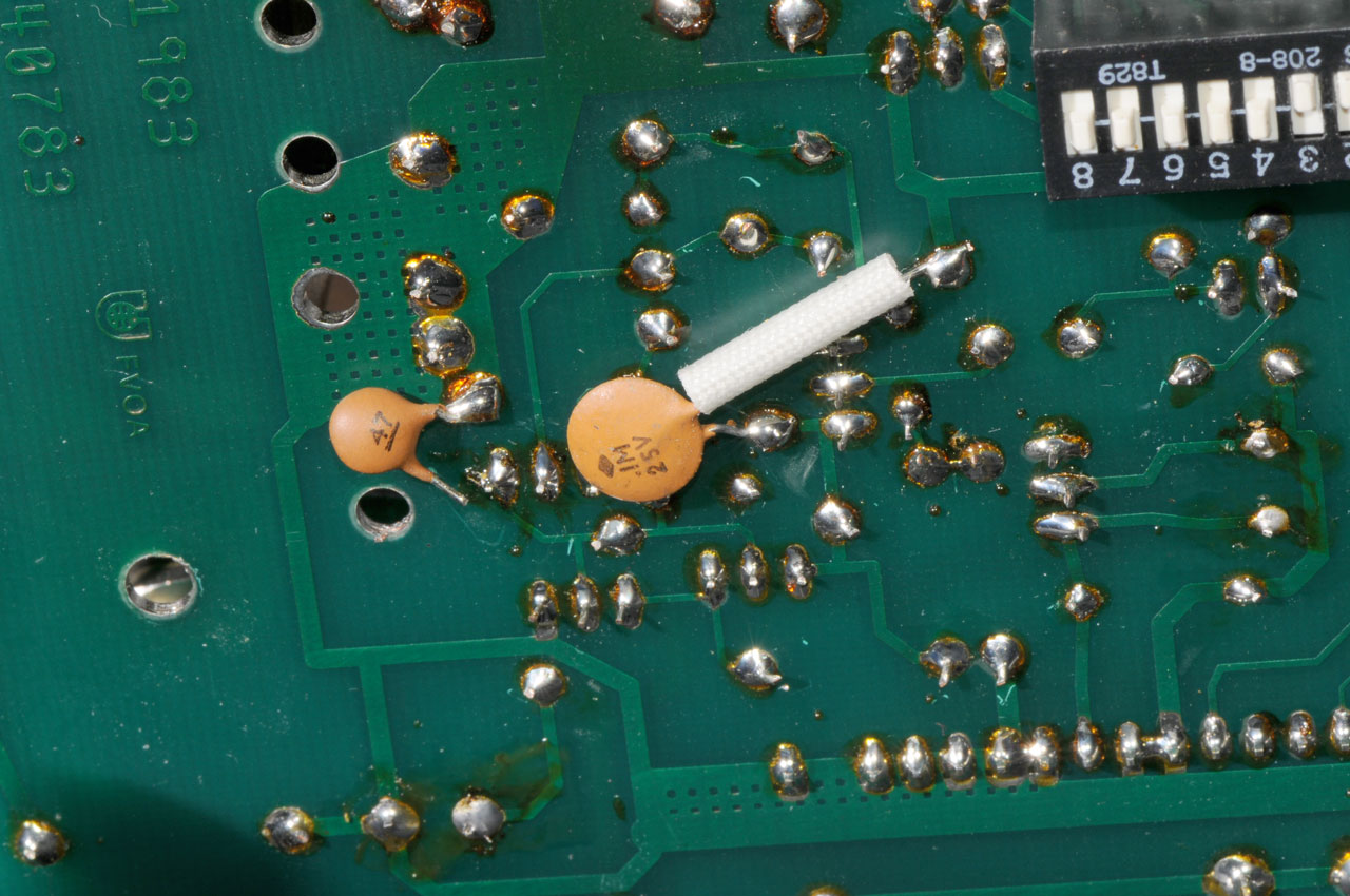
Mystery
Cap
on Bottom of Mother board
The cap with the sleeving
(C224) is in the manual, but the small cap marked
"47" is not.
Note the open connection is in a straight line with the
transformer mounting hole and a ventilation hole in the
PCB. If you look at the overall photo just above you
can see these holes and Q205 collector.
I have left the "47" cap disconnected, just as it is in
the photo.
It's connected between the collector of Q205 (the same as
the bases of Q206 & Q207 which are the totem pole
outputs for the 3.6 MHz signal). Most likely there
was an oscillation and the cap is there to stop it.
Note the capactive reactance is about 970 Ohms at 3.6 MHz
so will not effect that signal but would effect signals
above 36 MHz.
This (C225) cap is only found in factory assembled clocks,
not in the kits hence it's not in the assembly manual.
Re-Capping
The following are power supply or
decoupling caps where low ESR electrolytics would be good:
C102, C203, C205, C206, C208, C212, C213, C301, C354, C357, C401,
C404, C405, C424.
The following are caps where low leakage is important and so
either a plastic or low leakage electrolytic would be good:
C348, C353, C355, C359, C412, C414, C421, C422,C425.
Some 3-terminal linear voltage regulators might oscillate if the
capacitors used with them have too high or too low ESR values.
U201 +8 V out is a ST 78M08 "No
output cap needed for stability, but does improve transient
response"
U202 +5 V out is a Fairchild
UA7805 "No output cap needed for stability, but does improve
transient response"
But in this case there are no cap restrictions.
To remove the caps one lead was heated with a fine point soldering
iron and the case tilted to pull that lead out of the PCB.
Then the other lead was heated and the case tipped in the opposite
direction, pulling that lead out a little. The process was
repeated a few times to completly remove the cap. Then
solder wick and liquid flux were used to suck the solder out of
the hole. Sometimes it was necessary to add new solder and
flux both the PCB and solder wick to get it to work well.
I misplaced the 4-40 screw that connects the telescoping antenna
to the mounting bracket on the receiver and the first time I tried
the receiver used a longer screw. This had the effect of
lifting the receiver board up out of it's socket. After
cutting off the screw and re-tapping the threads in the bottom of
the antenna everything fit toghther properly. Also there was
a problem in getting the display board to seat fully that was
fixed by using a screwdriver to press directly on the socket.
Hi Spec
Once the above board seating
problems were overcome the clock was allowed to run and on my way
to bed noticed that there were two green LED lit (Capture and Hi
Spec) and the yellow Data LED was blinking. The time shown
had the correct minute and second values but was set for some
random time zone. Note this is with the clock indoors using
the telescoping antenna.
The improvement is solely due to the recapping. Although I
have spare 567 Phase Lock Loop and Op Amp ICs they have not been
installed.
The Hi Spec light seems to come on shortly after sunset at 5
MHz. Every day during the night it's in Hi Spec mode for a
number of hours.
The next thing to do is repeat the functional test
at 5, 10 & 15 MHz, then see if the IF bandwidth can be
determined by changing the carrier frequency up and down while
plotting the power level for threshold sensitivity.
Battery Backup
The DC Power plug has a positive
polarity center. It's 5.5 mm OD and has a 0.082" central
hole (2.08 mm). (Measuring)
This is commonly called a 2.1x5.5mm DC Power Plug.
I'd like to move the clock but not have it loose time or the 3.6
MHz VCO trim setting so will modify the backup cable to have Power Pole
connectors. First I checked the max input voltage spec for
U202 and it's 35 Volts. That way I can use one of the 257477BA-PP
battery adapters that holds 10 "D" batteries (15 Volts at full
charge for alkaline batteries). For backup Alkaline cells
are better than rechargeable cells since they hold their charge
for a much longer time (up to 10 years for the newest ones).
3.6 MHz Output
This is a WWV Disciplined Oscillator
(WWVDO or HFDO). The motherboard micro controller drives a
D/A converter that drives a crystal oscillator.
When the Hi Spec LED is on the tuning voltage is set.
There is a lot of distortion on the 3.6 Mhz output. Don't
know if that's normal or just the way it is.
Looked out to 500 MHz and did not see any spurious oscillations,
so the mystery cap (C225) is not needed to
suppress them.
The 3.6 Mhz crystal needs to have specific properties in order to
allow it's frequency to be pulled for tuning. I think the
Heath Heath Company used a Saunders
Associated model 150 Crystal Impedance meter to characterize
the crystals either in R&D or probably in production since it's
properties were critical to proper operation of the clock.
Note "Heath Company" property label on back panel.
Below is a summary of the
modifications I have done to the Heathkit GC-1000 Most Accurate
Clock to improve its performance:
1.) I replaced all of the IC sockets with machine tool pin
sockets. Having to re-seat some of the IC's every now and
then is unacceptable. I can't believe that HEATH used such
CHEAP IC sockets! (Well, maybe I can...)
2.) Re-designed the clock drive to the microprocessors. The
470pF AC coupled 3.600Mhz clock drive relied on the fact that the
input to the F8 uP's had a diode input clamp (probably the
substrate of the uP) and the input voltage would swing from -0.6V
to +3.5V. I replaced the cap with a 74HC14 CMOS driver with
am 82 Ohm series resistor (to match the impedance of the driver to
that of the PC board to reduce ringing). The voltage now
swings from ~ 0.2V to ~ 4.8V. Risetime of the clock remained about
the same.
3.) I also replaced the output transistor push-pull circuit that
drives the external 3.6000 Mhz output reference with a 74HC14
driver. I actually tied 3 of the inverter gates on the same
chip in parallel (prop delays are almost identical, so you can
usually get away with this) to drive this output. Created a nicer
looking waveform. This was the other half of the chip used
for the clock driver section (I used 1 gate of the other half for
the CPU clock driver, 2 gates remain unused (and tied off)).
4.) I added a second +5V regulator (78L05) and separated the D/A
Latch, R/2R resistor ladder and all associated circuitry that runs
the Colpits Oscillator / Varactor Diode / Clock Driver circuitry.
One cut on the top side of the PCB by the input inductor
(and the feed-thru hole) isolated the clock section +5V very
nicely. The problem I noticed is that when you turn on the
displays, the main +5V regulator would droop about 100mv causing
the D/A voltage to the varactor diode to droop. This was
enough to shift the 3.6000 Mhz frequency by ~ 15-20 Hz. Still
within the spec of the clock for output freq accuracy, but by
adding this second regulator the frequency now shifts less than
0.1 Hz (thats the resolution that my freq counter can measure to).
I also bypassed the clock section with a few 10uF Tantalum
caps to reduce switching noise.
5.) Eliminated the display ghosting (display shut off but the
5/10/10MHZ indicators still glow a little). This was accomplished
by simply grounding the unused side of the display enable switch
(labeled 3 + 6 on the schematic). You also need to cut the
power to the decoder IC U101 (pins 1 and 16) and take these two
pins directly to the power connector pins 1+2 (+5) on the display
board (before the switch). If you don't, when you shut the
display off IC U101 will load down the uP lines to it and the D/A
latch will always get loaded with 00H, thus screwing up the
ability of the clock to tweek its own oscillator frequency.
6.) Replace all of the caps associated with the 100Hz and 1Khz
tone decoder circuits with polypropolene or stacked foil caps.
This reduced the clocks sensitivity to temperature drift
(and thus lousy performance) during times when the display is on
and the insides of the clock heat up. I also replaced the 2
- 5K Ohm open face pots with 20 turn adjustable pots - much easier
to adjust accurately. The 2 phase-locked loop adjustments
are made much easier by just tying a high-impedance probe on pin 5
of the 567 PLL chip and adjusting the frequency to either 100.0 Hz
or 1000.0 hz. Much easier to adjust than Heath's method. (In
talking to the techs at Heath, they recommend this method over
that in the manual). Caps and everything were ordered from Digikey
for about $10 total.
7.) I added a MOV and a .001uF 1KV cap on the AC input to help
line noise rejection and spike suppression. I personally run
the clock off of a 12V 8AH GEL-CEL (I had sitting around for a
while, figured I better use it or loose it) and then use a
float-voltage charger for the battery (not a cycle- voltage
charger). I also added a 0.1 uF ceramic disc cap on the
output of the transformer (input to the full-wave bridge) for
added noise suppression.
8.) The transformer that HEATH supplies in the GC-1000 is just as
bad as the Radio-Shack transformers: They skimp on the wire
size AND the # of turns on the primary thus giving LOUSY line
regulation and they run HOT! DUMB! DUMB! DUMB! I only plug
my unit in when I move it (in case the 12VDC connector unplugs and
wipes out the previous months of clock oscillator tweeking).
If you use the transformer, replace it with a real one that
can handle the 800ma load without sagging so badly (and getting so
blasted HOT!).
9.) I also added a computer interface to directly look at the
5-10-15 Mhz band indication, HI-Spec LED and the 100Hz and 1Khz
tone decoder outputs. (The interface is nothing more than a 74HC14
inverter tied to the appropriate lines on the F8 uP). I have
a CMOS Z80 system monitoring these lines and when the clock goes
into or out of Hi-Spec, I kick the clock's serial interface and
store the time and band info in an EEPROM. I'm still writing
the code, but have the basic system working now (capturing data).
It will basically give me information on when the bands are
'open' to Ft Collins, CO. (which is 1240 miles west of me). I plan
on using the 100Hz and 1Khz data for a later project - To be able
to decode the WWV data stream myself (probably using a 68HC11 uP)
and create a real serial interface that tells you what time it IS,
not what time it WAS 1-2 seconds ago (the HEATH serial 'bit
banger' interface STINKS!) I'm still debating on whether to attack
the receiver section of the clock - It works ok, but it COULD be a
WHOLE lot better... hmmmmm...... anyone else
tweeked the receiver yet???
[It's a fun little project that keeps me out of trouble....]
--
John Gibbons
N8OBJ
Macedonia, Ohio
Internet Address: gibbonsj%iccgcc.dec...@consrt.rok.com
"Welcome My Son, Welcome
To The Machine" - Pink Floyd
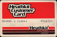
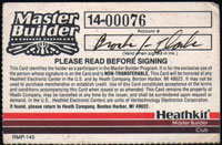
Heathkit ID Cards
These are two different cards.
The one on the left is just an ID card with my customer number.
The Master Builder card on the right has a different number and
was issued after I submitted a list of about three dozen Heathkits
that I had built.
Some of the earliest ones being the HiFi stereo AM/FM tuner and
separate power amplifier. To get stereo you needed to have
one channel on AM and the other on FM. Later added the stereo
subcarrier kit which allowed receiving stereo from a single FM
station.
July 2016 - An email I sent about Hi-Fi and some
Heathkit related stuff:
Scrambled TV
-----------------
In the 1950 - 1960 time frame I built a lot of Heathkits,
one of which was the tube type AM-FM stereo system (tuner
box and amp box). In stereo mode the tuner had one
channel coming from the AM radio and the other channel
coming from the FM radio. There was a San Francisco
station that broadcast on two frequencies (one AM and one
FM) so you could hear stereo.
Later Heathkit came out with a small add on box that was
an FM stereo decoder the sensed the 19 kHz pilot tone and
had stereo outputs.
It turns out that one form scrambled TV uses a 19 kHz
pilot tone as a way of regenerating the sync pulse.
So I modified the no longer used stereo converter box and
used it to watch the scrambled movies. http://www.prc68.com/I/HeathkitGC1000.shtml#ID
Barney
Amp
-----------------
The article said it was designed to work with a specific
phonograph cartridge since that was the highest fidelity
input source at the time. So probably would not make
a good amp for more modern input sources.
PS when playing records you need to match the stylus tip
size to the record. Small diamond tips for modern
33-1/3 RPM records and a larger ruby tip for 78 RPM
records (I didn't play many 45 RPM records).
The fidelity of 78s, with the correct tip, was really
good, but with the diamond tip that came with most players
they sounded scratchy.
Commercial Amps
--------------------------
In the mid 1970 I had a pair of Voice of the Theater
speakers built into a house. My son now has them.
An exponential horn and a 15" loudspeaker with their voice
coils in the same vertical plane.
That way there is no distortion at the 500 Hz crossover
frequency. http://www.prc68.com/I/HomeTheater.shtml#VOT
To go with them I got a top of the line Scott electronics
package. But when the music was quiet you could hear
noise.
It turns out that the noise spec on the Scott was some
number of dB below full output, but . . . .
the VOT speakers are extremely efficient and those mW of
noise were easy to hear.
The fix was to return the Scott and get Macintosh
electronics.
Heathkits came with a well written manual with line drawings
that, most of the time, were very clear. Pretty much every
time after assembling the kit it worked.
Recently I got a Saunders 150B Crystal
Impedance Meter and it has a Heath Company label on the
back. It may be that they tested all the individual
components to make sure they were in specification before
shipping them. That would go a long way to ensuring that
the kit works when assembled. If you know about the
Heathkit parts inspection policy let
me know.
Links on model number below to Heathkit Virtual Museum.
includes built-in color convergence
generator used with MacIntosh sound system and VOT
speakers
The MacMC2505 amp (Wiki)
and tuner were mounted on slides left & right buttons
released latch and could slide out. Retro
Audio Lab - rear
photo
Time & Date
Wind Speed & Direction
Indoor & outdoor temp.
Barometer
The computer interface generates so much RFI that I could
not use it.
The display and buttons are scanned.
Both wind sensors used the same optical disk, but with
different optical sensor arrangements.
The digital output was completely unflitered TTL levels so
when a ribbon cable was connected between the ID-4001 to
the SWTP6800 computer the
noise in the HF band was enormous.
Radio
Museum photos
When working with tube equipment it's easy
to burn out a resistor and not know it.
The value changes. Obvious when you
look inside and see brown or black and
your nose tells you something's wrong.
there are modern
units that do much more, but this is a quick and
easy way to determine NPN or PNP and identify the Emitter,
Base and Collector. Of course it also identifies
dead parts.
There were many more Heathkits, but my
memory limits what appears here.
Related
GC-1005 Electronic Clock
This is a line powered and
timed clock that reads out to seconds.
GCW-1001 Slave Clock
This is a slave clock that
needs a GCW-1001 Master clock with the power line
interface.
It uses a plug-in transformer (not a wall wart power
supply) and gets the time over the
A.C. mains at 120 kHz using a system like X-10 (Wiki).
The NE5050N IC has many features
that minimize power line noise.
Note the GCW-1001 is a WWV receiver like the GC-1001 Most
Accurate Clock that has
an optional PCB to transmit the X-10 like time signal to
slave clocks.
YouTube: Fran
Blanche: Heathkit
GC-1000 Power Supply Design Fails and Fixes, 19:57 - The
switch mode replacement regulator makes RF noise that stops the
clock from working. The input to the Voltage Regulator is
13.8 VDC, i.e. what you get from a "12 Volt" battery on the
external DC input jack. Restoring
The Heathkit GC-1000 Most Accurate Clock!, 43:03 - @ 5:00
- Problem caused by switching regulator, replaced by an
LM317 linear regulator, but she lowers the transformer voltage,
hence the battery backup will not work with a 12 volt battery.


