 CX-10239/PRC-74
|
|
|
|
|
|
I have one of these sets. It works with the T-784/GRC-109 (see Fair Radio Winter
Spring 1997 catalog page 11 for the T-784/GRC-109 Xmitter.
The xmitter has modifications to increase it's bandwidth, to allow
Morse code to be sent at a very high data rate (300 WPM).
This implies that some receiver would also need to have an
especially wide bandwidth to receive the signal from the
transmitter. Note that these xmitters were used by special
forces units operating behind enemy lines. By speeding up
the transmission it was much more difficult for an intercept
operator to pick up for two reasons, first it "spread" the
bandwidth making it harder to hear on a conventional receiver and
it reduced the time that the transmitter was on the air giving
"lower probability of intercept".
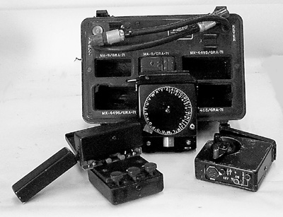
These were used in Vietnam by forward observers. The GRA-71
uses magnetic tape recorder technology to store the
messages. Each of the component parts has a heavy duty
military label with the manufacturer: Arvin Industries, Inc. and
the contract number: FR-36-039-E-5-15509(E). I think that
Arvin later changed their name to Motorola.
Overall Photo Another Photo from Toronto Surplus
There was an earlier
version(scroll to # 190) called the M-108 that had a similar
look, only it used paper tape in which holes were punched.
It also sent high speed Morse code by contact closure. If
you have any info on the M-108 or know about the radios it was
used with, please let me
know.
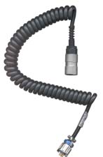
This keyer was introduced for the GRC-109 transmitter, but will also work
on a number of other transmitters like the PRC-64 (TM
11-5820-552-15), PRC-74A or B and the PRC-104.
There is a Russian version that has a telephone type dial with 12
positions (1, 2, 3, 4, 5, 6, 7, 8, 9,< ...>, 0,
<space>). It uses metal tape in a removable cartridge.
The lid is similar in concept to a Zippo lighter and can be removed. Once the lid is removed the tape magazine can be attached to the top. There is a two track tape head, the gear to drive the tape magazine and two pins with groves to allow the magazine to attach to the keyer. On the large face there is a manual crank to wind up the clockwork mechanism that will drive the tape over the head. There is a governor mechanism to regulate the tape speed.
On the bottom face are:
Inside there are two circuits that look to have almost the same components indicating that one is for "dots" and the other is for "dashes". When using magnetic tape, this type of coil tape head and the "mechanical pulse generator" the only type of data that can be recorded is a pulse, not a level. Therefore you can not record a dash, only a pulse on the dash head. I think that when the dash electronics see a pulse they wait for a time abut the length of a dash, close the switch that causes the transmitter to start sending and keep sending until 2 or three gear teeth have been turned. When the dot electronics see a pulse they wait a dot time then turn on the transmitter for one gear tooth. This is all guessing since I have not yet connected the GRA-71 to a transmitter for testing. The tape plays at 4.5 inches/second.
It is 3 1/8" high, 3 1/8" wide and 1 3/16" thick. The
newest date code found on the transistors in this unit was 6613
indicating the 13th week of 1966, or mid March 1966.
| Pin |
Function |
| A |
Chassis
ground |
| B |
nc |
| C |
12 V
return |
| D |
Signal
open NPN collector |
| E |
10 Ohms
to D |
| F |
Signal
return, emitter |
| H |
+12 V
<= 40 ma |
It has a hinged lid that is the same size as it is. The two
track tape head is at the end with the same provisions as
the MX-4496 to mount the tape magazine and a gear wheel to advance
the tape.
There is 12 feet of tape in a cartridge that will play for 32
seconds. This is good for 125 groups of 5 letters.
Along the bottom edge from left to right are three push buttons marked "." "S" and "_". That is dot, space and dash. The space button just advances the tape without writing any data. The dot sends a pulse to the "dot" recording head and advances the tape one gear tooth. The dash button writes a dash to the dash head and advanced the tape 2 or 3 (it is not clear to me) gear teeth. It uses the same "mechanical pulse generator" as the MX-4496 described below.
Note that this tape recorder and the MX-4496 write to the tape using no batteries or outside electrical power. This means that someone could use this kit to write tapes in a location that did not have any electrical power to be sent at a transmitter site that may be operated by someone else besides the person that posses the GRA-71. Since no batteries or other electrical power is needed to write the tapes this system is extremely reliable. A little over 3" high, 2 5/8" wide and 1 3/16" thick.
 This is one of the units
that writes data onto magnetic recording tape in the tape magazines.
This is one of the units
that writes data onto magnetic recording tape in the tape magazines.
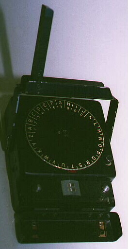
It can be fitted with one of two wheels that can be turned to 26 different positions with a nice feeling detent action. One wheel had the letters of the alphabet in a clockwise direction in white engraved letters on a black background. It also has the numbers from 1 to 9 then 0 clockwise starting with the letter A. The other wheel also has 26 positions. The letters of the alphabet nearest the outside are in a counterclockwise direction and are white. Inside these letters there is another alphabet in red letters going clockwise and with the letter A (red) next to the letter Z (white). Inside the red letters A through Q and the numbers 1 to 9 and 0. In the center along the edge of the MX-4496 closest to where the tape magazine fits (the top) is a red index mark abut the same width as one letter. To the upper left of the wheel is a black push button that advances the magnetic tape one unit but does not write any data on it. There is a "U" shaped handle that has it's hinge points about half way along the right and left sides and the handle part at the bottom. In the bottom part of the handle there is a fold out extension that when folded out extends the length of the handle to make it easier to operate it quickly and surely.
At the top there is a hinged cover that can be removed from it's hinge to allow attachment of a tape magazine. The tape head has two tracks. There is a gear that mates to the tape magazine to advance the tape with each stroke of the lever.
Inside the unit there is another wheel made of light brown colored insulating material like printed circuit board material but with no metalization. Mine has the letter T marked on it. This wheel is positioned by the outer code wheel. There are 12 pins arranged in two columns of 6 each. One column is for "Morse code "dots" and the other column is for "dashes". In a CCW direction the standard Morse alphabet is encoded in the wheel. For example "A" is the right column in row one and the left column in row two (dot dash). As the lever ii raised it just ratchets up and has no action. When the lever is lowered it causes the pins to lift first in row 1 then in row 2 and so on through row 6. In Morse code the 26 letter are represented by no more than four elements (dots or dashes). For the 4 element code there are: 2 (single character letters, E T) + 4 (two element characters A I M N) + 8 (three element characters D G K O R S U W) + 16 (four element characters B C F H J L P Q V X Y Z and 4 that are not used) for a total of 30 combinations.
As the lever is being pulled down a wheel with a ratchet mechanism causes a lever to move rapidly inside a coil of wire. The coil looks like what you would see on a relay. But in this case there are permanent magnets and an iron frame around this "mechanical pulse generator". Each time the toothed ratchet wheel snaps the lever a pulse of electricity is generated. There are two switches that can route the pulse to either the left or right recording head depending on whether a pin in the left column or the right column is allowed to raise up into the internal code wheel. There are also 6 cams that act like a car odometer to cause the sequential activation of rows 1 through 6. This unit is about 4.5" top to bottom, 3.25" wide and 1.25" thick.
It looks like a dot causes the tape to advance one gear tooth but
a dash causes it to advance 2 or 3 teeth and after the active
elements are through the tape does not advance. This seems
to be a good thing since it would not waste the tape.
28 Aug 2003 - Upon correcting some typos on this page it occurs to me that the two tracks on the tape are not dot and dash, but rather key down and key up commands.
| Pin |
Function |
| A |
Osc
Cathode |
| B |
PA
Cathode |
| C &
F |
Screen
Grid |
| D |
nc |
| E |
B+
Supply |
| H |
6.3 V
AC/DC |
| J |
Ground |
| K |
nc |
| L |
nc |
| Pins |
Function |
| A + B +
L |
Cathodes |
| E + L |
B+ |
| C, D,
F, H, J |
nc |
CX-10239/PRC-74| AUDIO |
WPI 126
Connnector |
||
| Gnd |
A |
A, C, F |
Chassis
Gnd 12 V return |
| headphones |
B |
nc |
nc |
| PTT |
C |
A, C, F |
Chassis
Gnd 12 V return |
| Mike |
D |
nc |
|
| CW Key |
E |
D |
Open NPN
collector |
| P.S.* |
F |
H |
signal
return |
CHAPTER 1
FUNCTIONING OF RECORDER-REPRODUCER, SOUND RD-265/GR
Section I. SYSTEM FUNCTIONING
.......
2. System Application
.......
a. The recorder-reproducer is a three-channel, audio frequency
record and playback unit that uses three-track endless loop
magnetic tape cartridges. Two of the channels are used to record
and reproduce audio information. The third channel is used to
record and sense a control signal (cue tone). The recorder
assembly is primarily intended to record, on magnetic tape,
high-speed Morse code data transmitted at speeds up to 300 words
per minute. The outputs of the two audio information channels in
the reproducer assembly, are separately applied to individual
earpieces of a binaural headset. The cue tone signal is recorded
at the start of each message on the third track of the tape. A
third channel in the recorder-reproducer is used to sense the
presence of the cue tone. Whenever the cue tone is sensed (record
or playback operation), the tape drive is disabled. In the record
operation, it prevents the recording of additional information
over the initial recording. In the playback operation, it insures
that the tape is in the proper position to play back the
information from the beginning of the recording.
b. The recorder-reproducer is used with two communications
receivers, operated in diversity mode. The intermediate-frequency
(IF) output of each receiver is converted to 10 kilocycle (kc) and
applied to the audio channels of the recorder- reproducer. The
continuous-wave (cw) information is recorded on magnetic tape at a
speed of approximately 15 inches per second. The recorded
information is later played back on a reproducer with a variable
speed of 0.5 to 2 inches per second (ips) (10 to 40 words per
minute (wpm)), thereby enabling the operator to select a speed
which is compatible with his copying ability. The playback speed
selected (0.5 to 2 ips) reduces the recorded 10-kc frequency to a
lower frequency (approximately 333 cycles per second (cps) to
1,333 cps).
Listing of the GRC-109 and component parts, some photos.
This file lists some observed info on the GRC-109, RS-1, RS-6, PRC-64, and GRA-71 equipment.
Clandestine Radio Equipment of the United States' Cold War Era - 2nd edition (preliminary), 1999 Pete's GRA-71 page -
FM 24-24 Signal Data References: Signal Equipment
This manual is on line maintained by the U.S. Army. Chapter 4 Section 3: Auxiliary Radio Equipment has a GRA-71 listing
TM 11-5835-224-12 = 019010.pdf on ETM
Operator and Organizational Maintenance Manual
Coder-Burst Transmission Group AN/GRA-71
May 1964
TM 11-5835-224-34P
Direct Support and General Support Maintenance Repair Parts and Special Tools Lists (Including Depot maintenance Repair Parts and Special Tools) For Coder-Burst Transmission Group AN/GRA-71
(NSN 5820-00-056-6856)
July 1978
TM 11-5820-474-14
Operator, Organizational, and Field Maintenance Manual:
Radio Set AN/GRC-109
18 May 1962
TM 11-5835-224-12
Operator's and Organizational Maintenance Manual
Coder-Burst Transmission Group AN/GRA-71
(NSN 5820-00-056-6860)
With changes C 2 and C 5
TM 11-5835-224-35
DS, GS and Depot Maintenance Manual
Including Repair Parts and Special Tool Lists
Coder-Burst Transmission Group AN/GRA-71
July 1969
Unclassified
MWO 11-5820-474-35/1
Modification of Radio Set AN/GRC-109 to make it Compatible with Coder-Burst Transmission Group AN/GRA-71
TB 11-5820-890-10-12
Operation of Lightweight Tacfire AN/PYC-1 (BCT) and AN/PSC-2 (DCT) with SINCGARS ground radio setsTM 11-5835-228-34
DS and GS Maintenance Manual Recorder-Reproducer, Sound RD-265/GRTM 11-5835-228-20P
Organizational Maintenance Repair Parts and Special Tools for Recorder-Reproducer sound RD-265/GR
(NSN 5835-00-901-1086)
Back to Brooke's Products for Sale, Crypto , Brooke's Military Information page
This is the [an error occurred while processing this directive] time this page has been accessed since 2 Feb. 2000.