

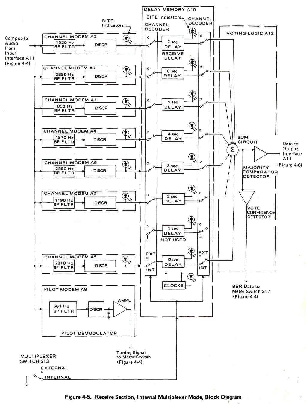
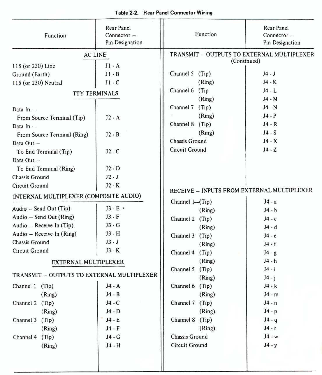
BR Communications (later merged with TCI to become TCI/BR, later bought by Dielectric Inc ) makes a line of chirp sounder transmitters and receivers. See my RCS-5 Chirp Sounder page for more on this. One of the features of the Chirp Sounder system is that a narrow shift order wire signal is superimposed on the carrier that is sweeping up in frequency from 2 to typically 30 MHz. This short order wire message has a very high probability of being received anywhere in the world. I think that BR communications developed a line of HF radio modems to try an offer a similar high reliability of contact communications.The MD-1142 aka BR 6029C has two modes of operation both are full fuplex (the receiver and transmitter sections are fully independent), in the Internal Multiplexer Mode a single TTY signal is fed to 7 different channels and the signal in each channel is time delayed by 1 second form all the other channels. In addition there is a pilot tone at 561.1 Hz. This mode of operation provides a high probability of getting the message through. In the External Multiplexer Mode each of the 8 channels is fed or receives a separate data stream so it does not have the redundancy of the IMM. In time order the channels are:
Chan # Center Freq Delay sec. 3 1530 0 7 2890 1 1 850 2 4 1870 3 6 2550 4 2 1190 5 5 2210 7 8 561 pilot tone The receive block diagram in IMM mode - there is a majority voting circuit so it takes at least 4 seconds of 7 good to work correctly, or a 3 second dropout can be tolerated.
The rear panel label reads
MD-1142/UGC Modem, Time Diversity
NSN 5805-01-105-0023 Des. Act. 33783
Serial No. 83042
Contract FO4606-83-C-0843 US
Model 6029C Part No. 6029-1500-012 Rev A BR Communications
Made in USA The inputs and outputs can be either Low Polar (TTL) signals or audio tones, NOT current loop.
The manual is 0040-6029-15005 and contains Installation, Operation, Theory of Operation, Maintenance with parts breakdown and schematics. The construction is similar to the RCS-5A receiver, that is a mother board with plug in daughter baords for each function.
It uses discrete components and CMOS logic, no microprocessor or remote control.
The AC power cord terminates in an MS type connector that has an OD of about 0.685" with 3 female sockets A, B and C.
The part with the OD of 0.685 has a single alignment slot.
A = Line hot (black)
B = Line Neutral (White)
C = Earth Ground (Green)
The manual calles for:(the line power connector on the RCS-5A is larger, it's a Bendix MS-3106A-16-10S with an M85049/41-8A cable clamp.
- MS-3106A-14S-7S connector on the power cord
- 97-3057-1007-1 cable clamp
- 9779-513-6 rubber bushing
- Looks like an ISI Circular MS Connector -
The CV-89A/URA-8A is a Military tube type FSK converter with a CRT type tuning indicator.
The CV-483/URA-17 is a solid state FSK converter with a CRT type tuning indicator.
The Frederick 1203 FSK Demodulator
The Frederick 600A BER test set
Digital Radio Modes
Digitech also made a modular rack mount Digital Data Generator
RCS-5 Chirp Sounder Receivers
2844650 Teletypewriter systems or the like, Oscar B Dutton, Hoffman Electronics, 1958-07-22, 370/302; 340/12.17; 340/12.2; 375/260; 375/275 - with cited and calling patents
Mike Murphy Surplus - where I got mine
WUN - Digital Signals FAQ - BR6028, BARRIE, USA 7 channel modemBack to Brooke's Products for Sale, Military Information, Time & Frequency, Electronics, Home page- current products for sale, Contact
page created 31 July 2001