WSPR (Wiki)
"Weak Signal Propagation Reporter" Intended for propagation
analysis and/or antenna testing, does not include provision for
data communication.
Official web page - http://physics.princeton.edu/pulsar/K1JT/wspr.html
- software designed to be used with SSB HF radio and a computer
sound card.
wsprnet.org - maps and logging
QRP-Labs - has a
relay filter bank as an option for their WSPR transmitter (6 Tx
frequencies) as well as a GPS receiver for keeping time, RF
frequency & Grid square.
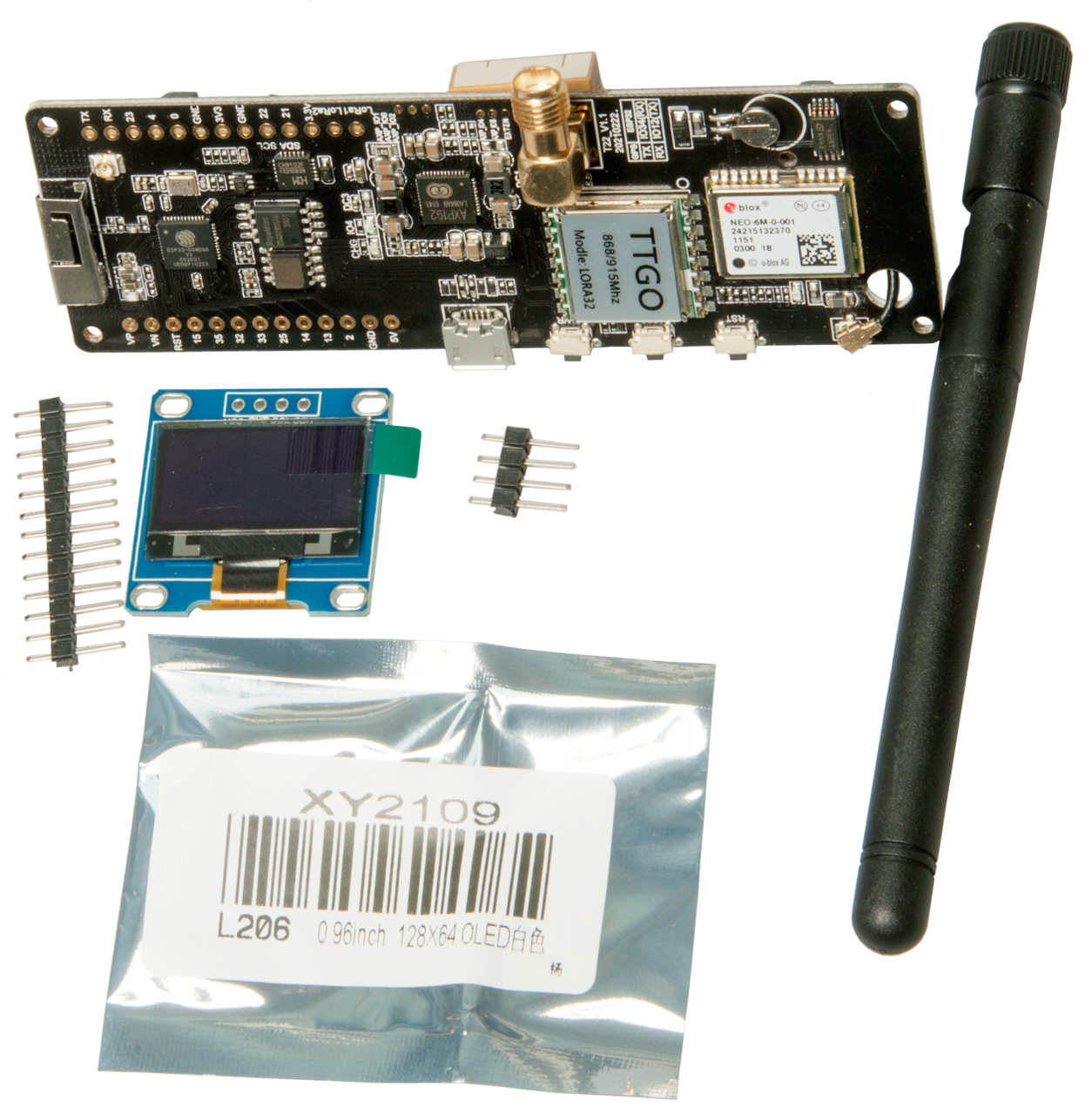
WSPRlite
- SotaBeams: UK based standalone WSPR single frequency
transmitter- Classic SB
or Flexi
-
WSPR Rocks
- many sub pages including balloons.
Photo
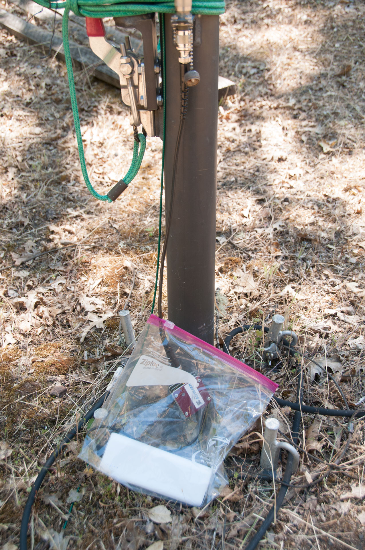 |
WSPRlite Flexi beacon transmitter at base
of TCI-651 antenna With Power Bank recommended for GoPro camera where my existing power bank did not work. SotaBeams says some power banks turn off if they don't see enough load. The transmitter has microUSB for DC power and programming. SMAf for RF out, a status LED and a start push button. A very simple setup. But the timing of the press and hold for start needs to be accurate to maybe 0.1 seconds, 2 seconds is far enough from correct to prevent proper reception. |
20 June 2018 borrowed a WSPRlite Flexi - has the following frequencies built-in, only one per configuration:
power out 200 mW and lower. The classic SB model has fewer frequencies but includes a couple of filters.
| meters |
MHz Flexi |
MHz SB |
| 630 |
0.474200 |
|
| 160 | 1.836600 |
|
| 80 |
3.592600 |
|
| 60 |
? |
|
| 60 |
? |
|
| 40 |
7.038600 |
|
| 30 |
10.138700 |
Filter |
| 20 |
14.095600 |
Filter |
| 17 |
18.160100 |
na |
| 15 |
21.096100 |
na |
| 12 |
24.926100 |
na |
| 10 |
28.126100 |
na |
| 6 |
50.294500 |
na |
Spectrum Plots on 4395A using a 3 foot wire as antenna. This was done as a check that the transmitter was working.
The Wiki WSPR page says the bandwidth is 6 Hz. So what your seeing in these two plots is the SA IF BW.
80 meters 3.570125 MHz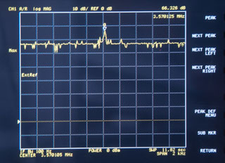 |
40 meters 7.040104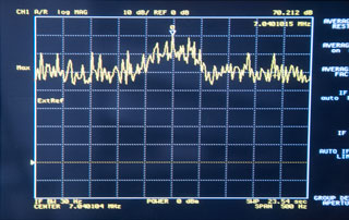 |
Configuration
Prior to using the WSPRlite it needs to be programmed using the
USB-micro port for both power and data.
That can be done using a standard USB-A to USB-microB cable and
a laptop or desktop computer or a USB-microB to that matches
your cell phone with OTG capability.
USB On-The-Go (Wiki)
allows connecting two devices where one acts as the host.
Intended for things like memory, keyboards, mouse,
&Etc. Allows the WSPRlite app to both configure the
beacon transmitter and to also start it at the exact time
needed. But to remove the phone and keep the beacon
transmitting requires a Y-cable.
| Turns out this does NOT fit the
LG-998T phone, connectors 6.81mm wide (Mini-B), but need to be 8.2mm i.e. the cell phone is USB-C. |
This is a USB-Bmicro cable - WRONG cable
for LG G6.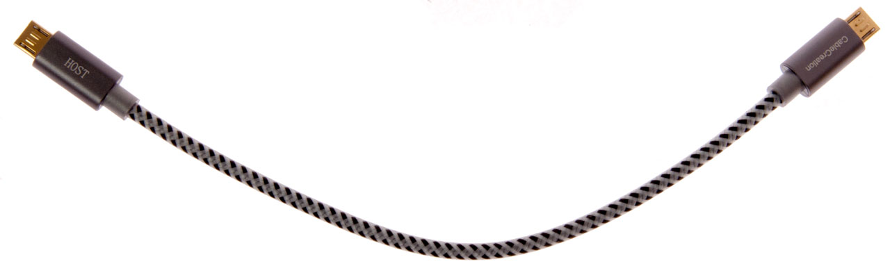 |
<- This is a Cable Creation p/n: CC0756 UPC: X001HH6U8R Length" 0.2m (8") eBay search term: "Micro USB Male to Micro USB Male OTG Cable Data Transfer" The cable is asymmetrical and one end is labeled "Host". The WRONG cable! |
| Fig 1 Cables for OTG configuration &
starting Note USB-C at phone end and USB-Af going to "Y" USB-A cable. 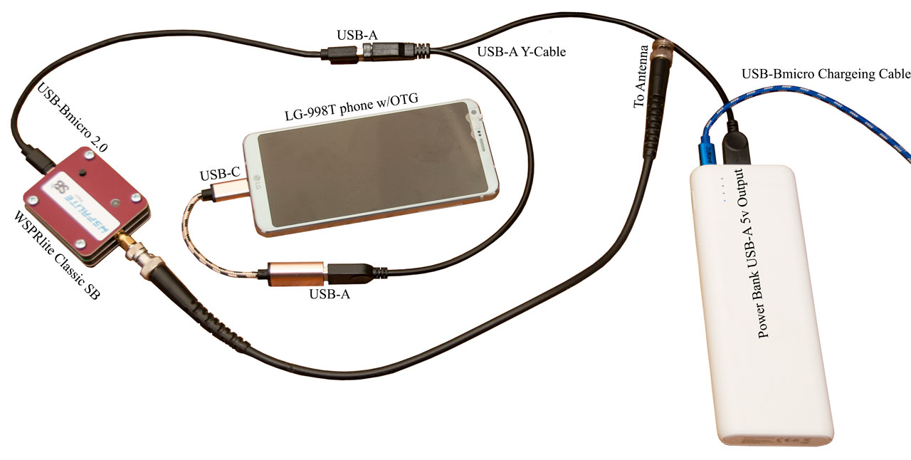 |
Although not marked on the Y-cable, one of
the USB-A connectors only carries DC while the other one will work for data. To test connect WSPRlite to computer using Y-cable and see which leg supports configuration. For this Y-cable the other leg does NOT support any data, only DC. Note: the cable from the phone to the USB-A socket needs to match your phone. Mine happens to be a USB-C connector, but prior phones have used USB-Bmini and USB-Bmicro connectors. |
|
Fig 2 Set-up prior to tapping Auto-Start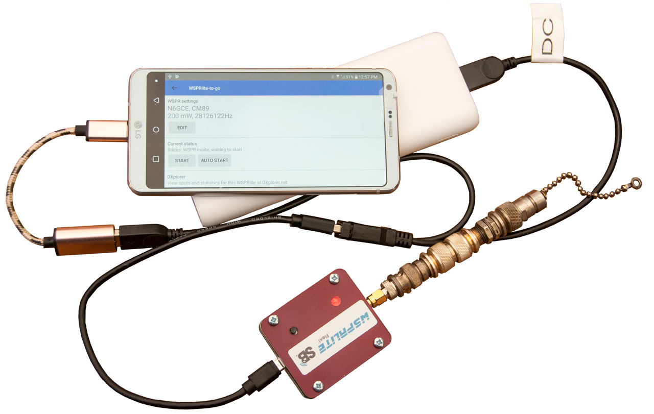 |
Fig 3 Counting down for auto-start to
activate beacon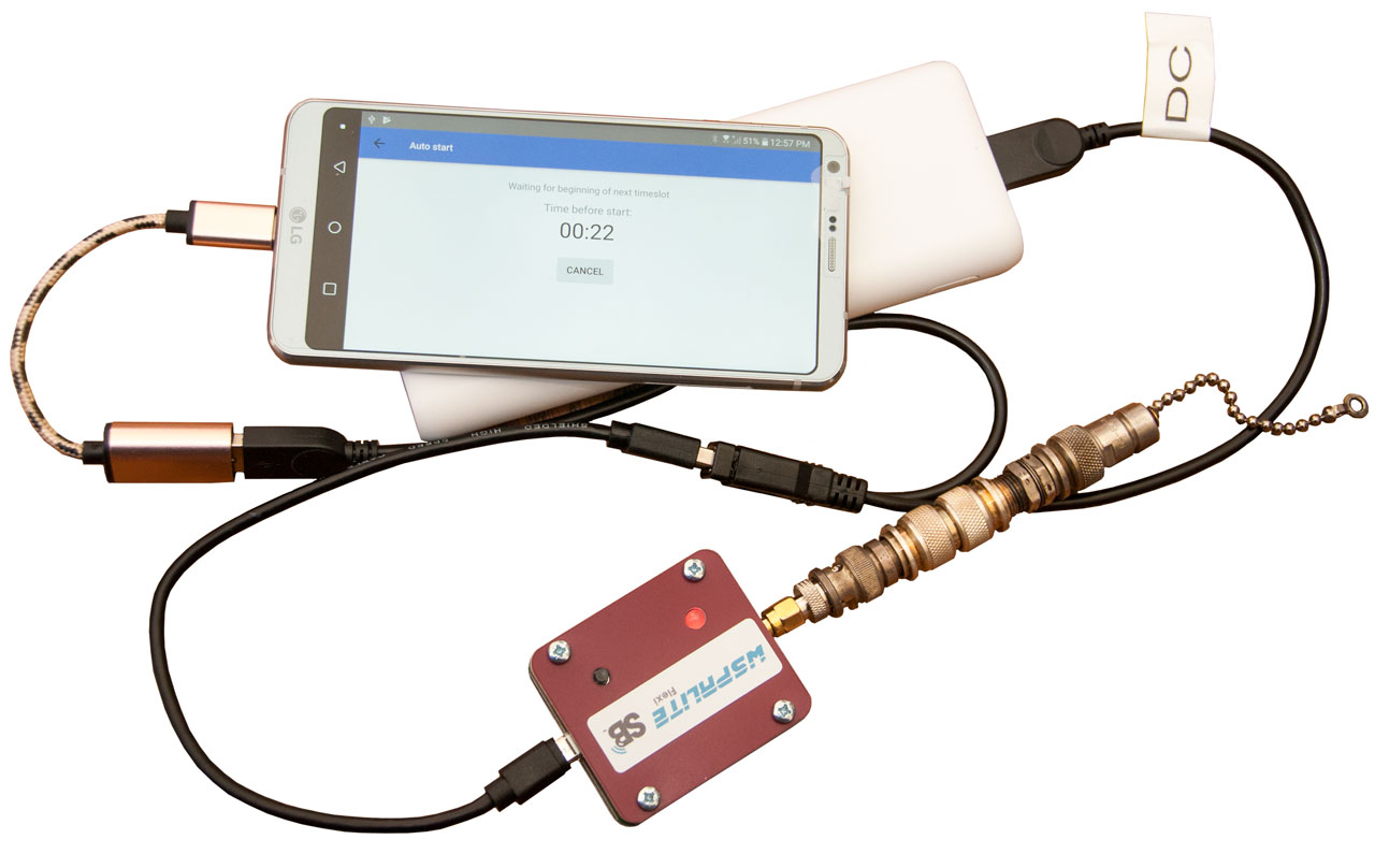 |
Fig 4 beacon has been activated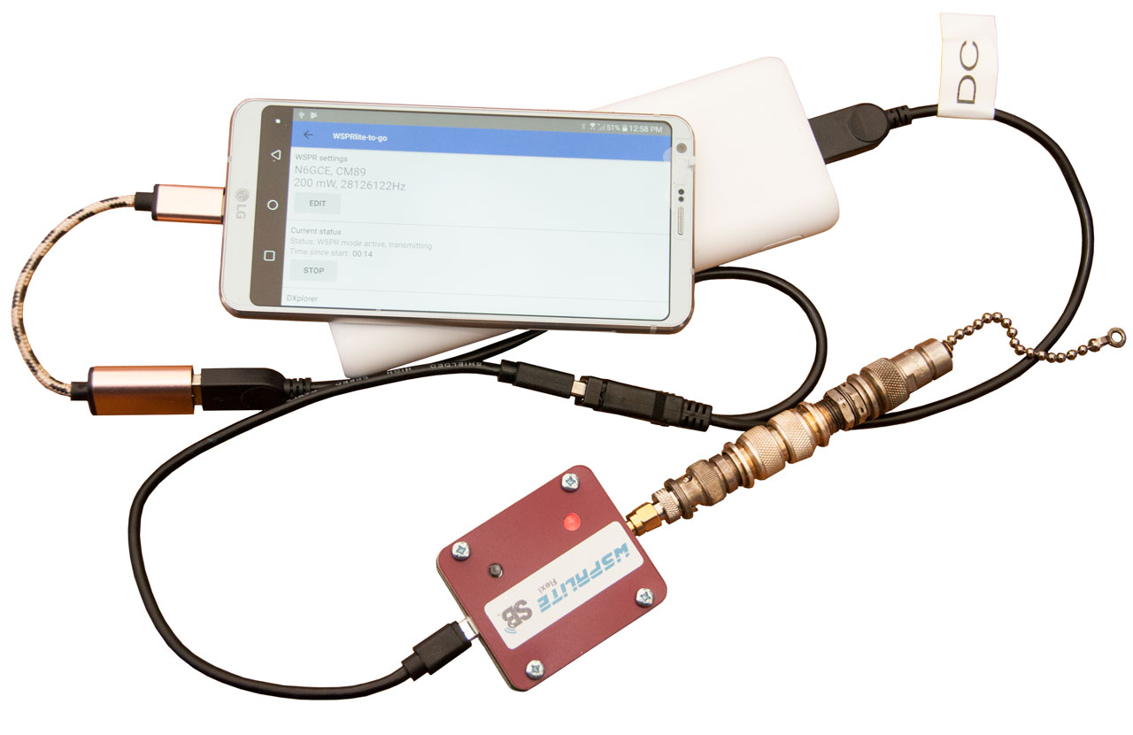 |
| Fig 5 Cell phone can be removed and beacon
gets DC from power bank. 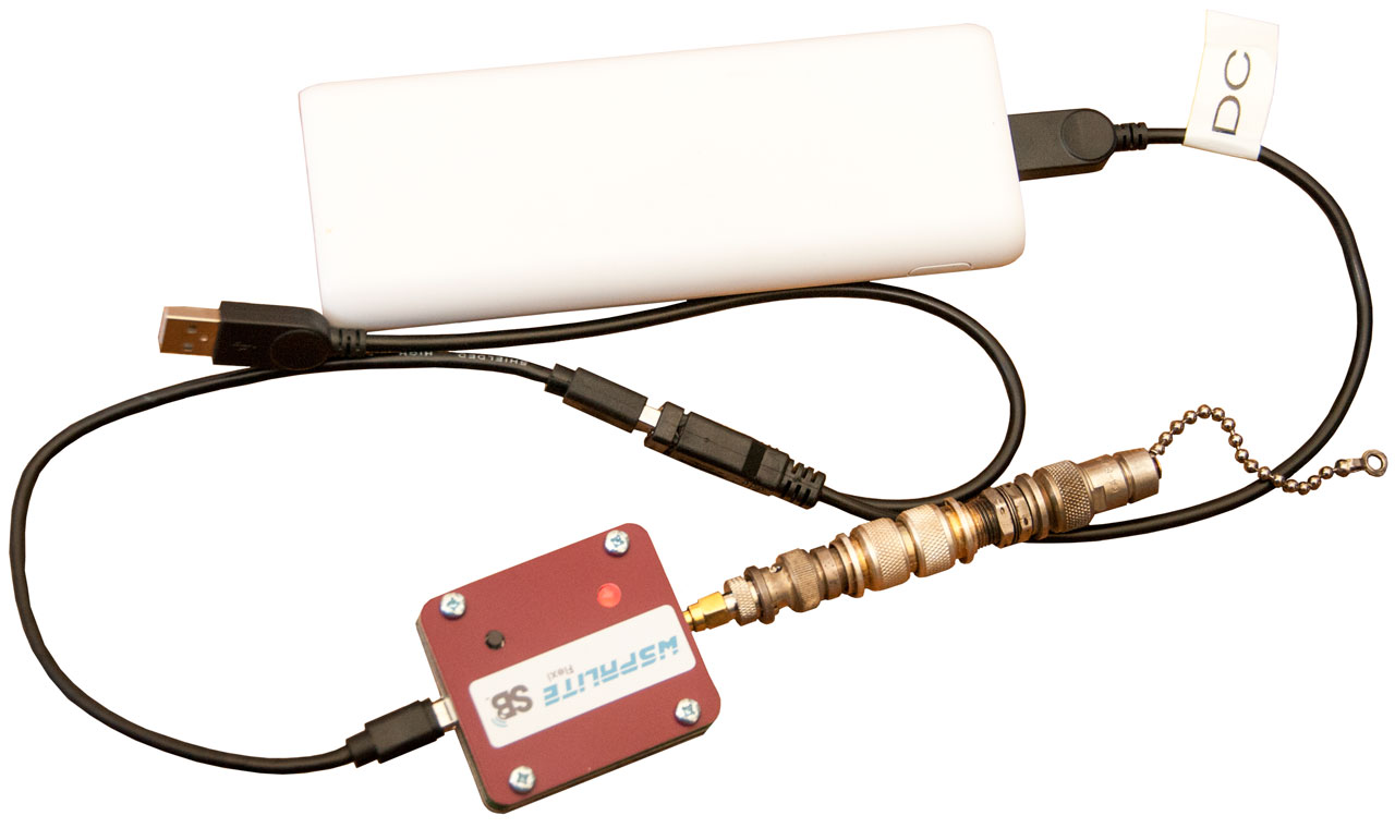 |
The problem is that if the start transmission function is used
in the phone then the phone is powering the WSPRlite. When
the phone is unplugged the WSPRlite stops, so a "Y" cable is
needed to take advantage of the app auto start function.
The Y-cable sold by SotaBeams (web
page) seems to have a USBA socket and so is a two cable
solution.
I have on order (eBay title: "USB OTG Power Y Cable") It
has a USB-A plug for the power bank, a USB-A socket for the
existing WSPRlite power/programming cable & a USB-microB
plug for the cell phone. I'm guessing this is what the
SotaBeams cable is, so it will take two cables.
To determine if your phone supports USB OTG use the Android app
"USB OTF Checker". The LG-VS988T does support it.
Part of the configuration is the Grid Square location of the
beacon. Here's a web
page to help with that. Note only the first 4
characters are used by WSPR.
A Note on USB
When USB first came out it was a fantastic improvement on RS-232.
It turns out the RS-232 was an agreement to NOT have a standard. The pin assignments (Tx on 2 or 3?), number of pins (9 or 25) in the connector and sex (pin or socket), type of handshake (hardware, ACK/NAK,, none), parity bits (none, 1, 2, even or odd) are not fixed, so in order to get two devices to talk in "RS-232" you need a custom cable or a stock cable (straight or null modem?), BAUD rate (select from a long list or auto determined) and a bunch of adapters to get it working and settings on the computer to match. That all went away when USB was introduced because there was USB-A where the desktop or laptop computer had a USB-A socket. The one and only cable had a USB-A plug to a USB-B plug and the other device had a USB-B socket. But then people wanted video and USB was to slow so, Firewire came out as something different. That didn't last long and USB got faster and then the "B" connectors started changing. Now there are B, Bmini, Bmicro and C connectors and various number versions of USB like 2.0, 3.0 &Etc
So, USB has become an agreement to not have a standard. Just like RS-232 you need to specify which flavors of USB cable you want. This allows retailers to sell cables without specifying the connector and instead specifying what models of phones they fit. Of course this is accompanied by a price 10X higher than what you would pay for the generic cable.
Operation - Starting at the correct
time.
After using time.is web page on
my cell phone, I started getting signal reports.
It's also important to start on an even minute, which I may have
done by accident.
The time to send one frame is just under 2 minutes.
"Press the button 2 seconds after the start of an even
minute.
It turns out that the time shown on my WIN7 desktop computer
was off by 1.8 seconds and my LG-VS988T cell phone does not
display seconds on the clock.
The desktop clock was fixed by using Dimension4
software. Now the desktop computer agrees with the UltraLink WWVB receiver and
time.is web page.
I added the
ClockSync app to the cell phone but unless you root your
android phone it can NOT set the system clock. But it does
have a seconds display. This is because the Android system
forbids apps from changing the system time or date, probably
because if you could do that, then you could keep trying the
demo version by setting the clock back to when you loaded the
app.
home
page - Vimeo: ClockSync assisted (Rootless) mode - this only works when the cell phone
is off by 30 seconds or more. It can NOT set the phone's
clock to fractions of a second.
Need to find a GPS app that displays seconds or use time.is.
I've added the time.is web page as an icon on my cell phone
making it easy to call up.
Reports
The most striking thing I learned is about the importance of the antenna. A station in Canada, almost directly North of me (maybe 1,000 miles) was hearing me 20 dB louder than everyone else. It turns out he was using the "AG6IF HF Ham radio Sky Loop" horizontal antenna. The TCI-651 antenna I'm using is a crossed delta loop with circular polarization. So these two work together. Note the AG6IF antenna will work when near (6') the ground, but better if up 1/4 wave.Balun Designs model 25113 (may be a replacement for the AG6IF Talented Balun which is no longer available). "...247 to 251 feet of insulated wire configured in a horizontal delta loop will provide SWR below 2:1 on 80, 40, 20, 15, and 10 meters"
-------------------------------------------------------
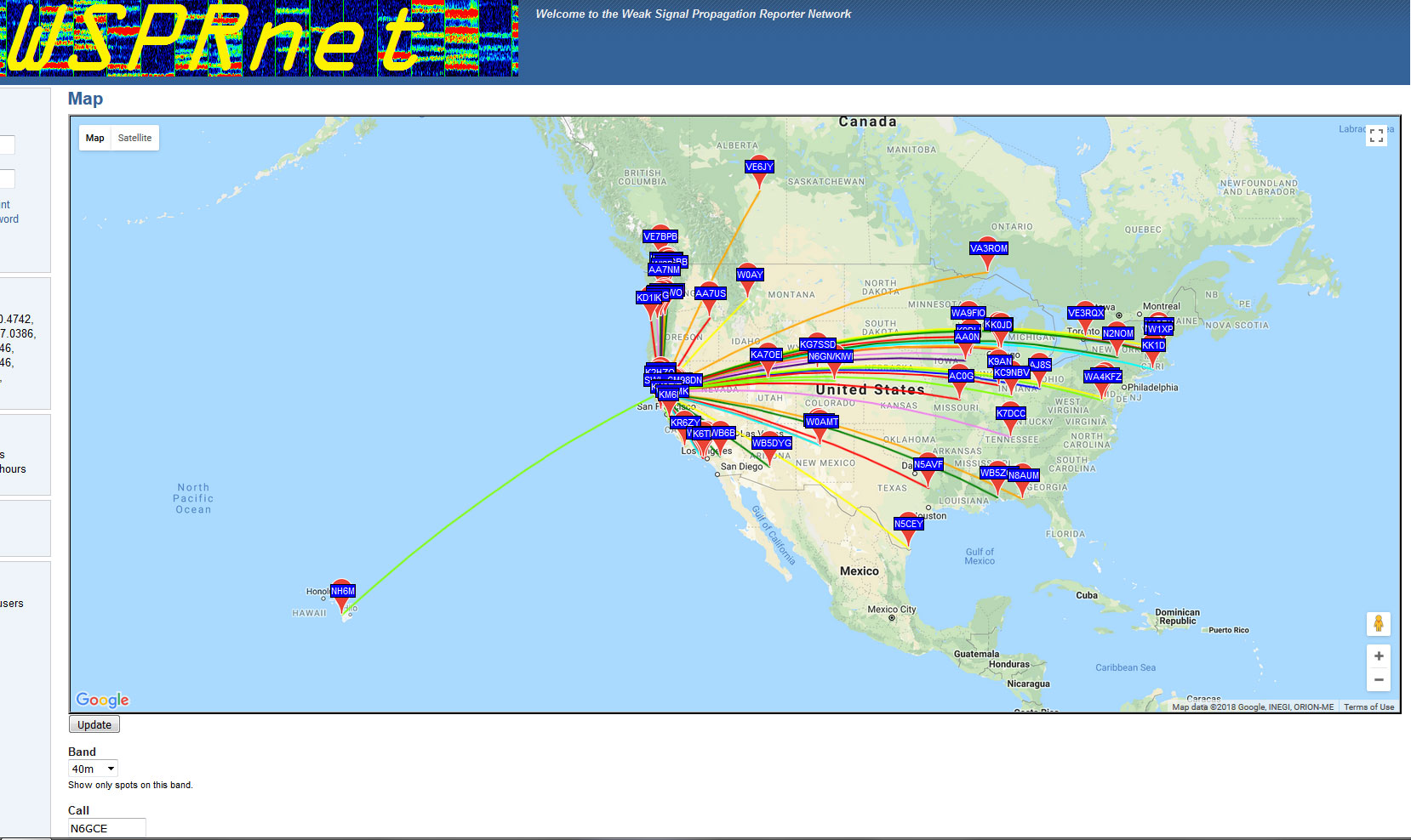
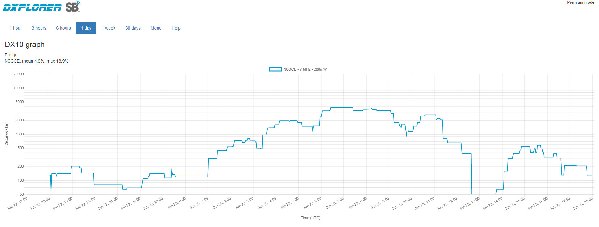
reports in the first hour of operation
DX10: N6GCE - 7 MHz - 200mW
| Distance (km) | Call | Spots count | Last seen |
|---|---|---|---|
| 652 | KD7OFU | 1 | 2018-06-22 18:58 |
| 646 | W7OWO | 12 | 2018-06-22 17:02 to 20:26 |
| 246 | KM6I | 2 | 2018-06-22 18:06 to 18:26 |
| 174 | KK6ZIZ | 7 | 2018-06-22 17:02 to 18:20 |
| 173 | KP4MD | 4 | 2018-06-22 17:02 to 18:26 |
| 155 | KPH | 20 | 2018-06-22 17:02 to 20:14 |
| 153 | SWL-CM98DN | 1 | 2018-06-22 17:04 |
------------------------------------------------------
Maps & Graphs
| 160m (26 June 2018) Only my friend K2HZO can here me |
80m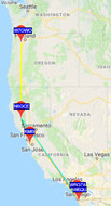 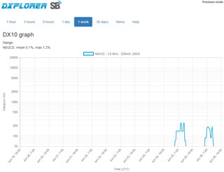 |
40m
|
||||||||||||||||||||||||||||||||||||||||||||||||||||||||||||||||||||||||||||||||||||||||||||||||||||||||||||||||||||||||||||||||||||||||||||||||||||||||||||||||||||||||||||||||||||||||||||||||||||||||||||||||||||||||||||||||||||||||||||||||||||||||||
| 30m |
20m (27 June 2018) Heard immediatly by K7QXY 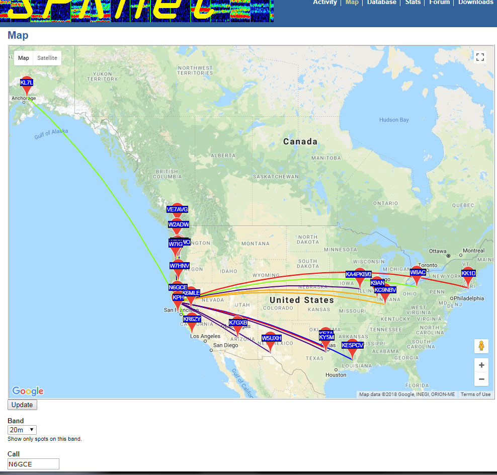 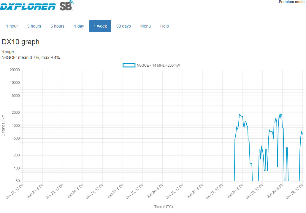 |
10m (29 June 2018)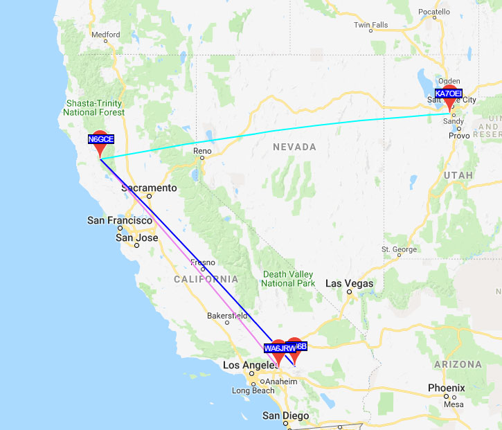 sorted by S/N (notice all contacts late at night
|
||||||||||||||||||||||||||||||||||||||||||||||||||||||||||||||||||||||||||||||||||||||||||||||||||||||||||||||||||||||||||||||||||||||||||||||||||||||||||||||||||||||||||||||||||||||||||||||||||||||||||||||||||||||||||||||||||||||||||||||||||||||||||
| 6m (5 July 2018) |

WSPR & MH370 (Wiki)
YouTube: A New Trace! The Full MH370 Story, so Far.., 56:05 - @46:10 WSPRDropBox: MH370 Flight Path Analaysis - 31st August 2023 -
WSJT (Wiki)
A package of Weak Signal (WS) digital modes.WSJT Home Page by K1JT - includes a sub page for WSPR -
WSPR archived data used to locate MH370. See: MH370 Search.
Chirp
Although chirp transmitters are intended for measuring H.F. propagation they do have a MSK like order wire mode where a short message is sent over and over again and the transmitter sweeps from 2 to 30 Mhz. If there's a path somewhere in that range the message gets through.Automatic Link Establishment (Wiki: ALE)
This really is not a mode, but rather a protocol for linking HF radios automatically. Each radio in a net periodically polls the other radios in the net and keeps track of what frequencies work for which radios in the net at different times of day. By remembering when and on what frequencies a station is heard, the radio can make a good guess at what frequency to use whenever one of those stations needs to be contacted.Groups.io: MARS-ALE-Radio-Systems - Harris Radio -