Background
The PC33C is the prior generation
general use security camera at Super Circuits. The current
general use cameras (4th Generation) cost 50 to 250% more. This
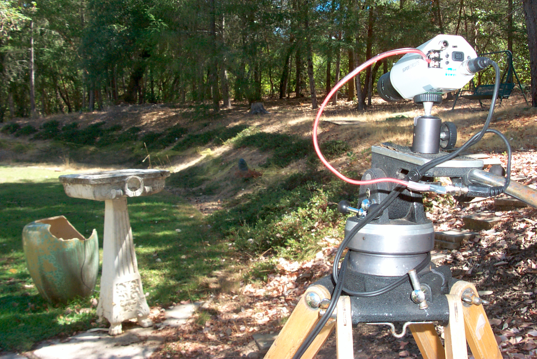
camera has been sitting outside (great California wine country weather)
for the last week or so feeding the 24/7 still image web cam.
The Kodak DC290 still camera that took the above photo sure has much
better quality than the TV cameras shooting the same scene. I
hope that is just because the camera is not properly setup. It
also may be the setup of the digitizer in the computer.
Arri Tripod holding camera. The
siamese cable from the P164C has a male DC power plug, so I've made a
short pigtale adapter that feeds the 12 VDC to the camera.
Rear Panel
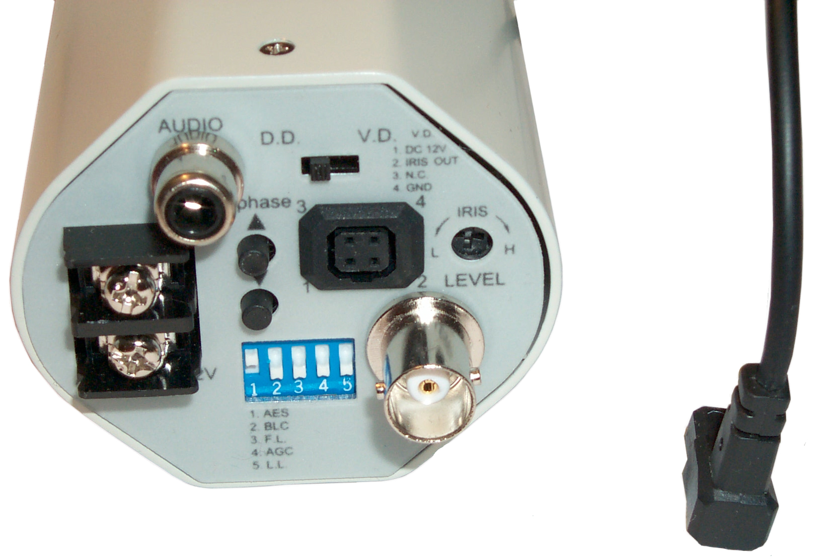 Audio Out on RCA connector.
Switch for DC Diaphragm or Video Diaphragm i.e. Auto Iris.
Pot for DC Auto Iris level.
Up and Down buttons for phase when A.C. power is used. multiple cameras should make phase the same on all cameras when A.C. power connected. The cable shown is from an Auto Iris lens and that's the orientation of the plug. It seems that all the DC auto iris lens have the same plug. Video type auto iris lens may come with bare wires.
DIP switches for:
1 AES = Automatic Electronic Shutter OFF for Auto Iris Lens otherwise OFF (this works at the light input stage)
2 BLC = Back Light Compensation. Normally off, when ON increases exposure. May be interesting in low light situations.
3 FL = Flicker Lock. Normally OFF. Only used when needed.
4 AGC = Automatic Gain Control. Normally OFF. (This works on the output signal)
5 LL = Line Lock. When ON camera syncs to A.C. power line so can only be used when A.C. is used for power. Otherwise OFF and camera syncs to internal crystal oscillator.
Auto Iris Lens
 This
is a fixed 4.0 mm focal length DC Auto Iris lens. The only
adjustment is for focus. But there is a 4 corner sun shade which
should be in the correct rotation and to get that you need to loosen
the set screw (hole visible in photo at left on camera body).
This
is a fixed 4.0 mm focal length DC Auto Iris lens. The only
adjustment is for focus. But there is a 4 corner sun shade which
should be in the correct rotation and to get that you need to loosen
the set screw (hole visible in photo at left on camera body).The white cylinder in the photo is a small motor that controls the iris diaphragm. When no power is applied it's closed all the way to no light.
Inside
To open remove the single screw at the front and rear top (holes visible in photo at left.).
Push rear panel forward until it stops at the mounting threaded inserts.
Unplug the big connector from the CCD assembly.
Unplug the 3 wire cable from the center power supply board.
From behind the camera the Red wire in each cable connects to the Right.
Push rear panel forward until it stops at the mounting threaded inserts.
Unplug the big connector from the CCD assembly.
Unplug the 3 wire cable from the center power supply board.
From behind the camera the Red wire in each cable connects to the Right.

CCD Assy
The big IC on the CCD assembly is a Sony CXD2163BA.In addition to the 1/3" Color CCD at the front there is also a microphone and a LED.
This CCD is rated for 0.4 Lux at f1.4.
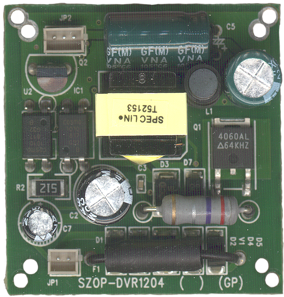
Power Supply Assy
The center board gets it's input on JP1 from the two screw terminals on the rear panel. The output DC goes to the CDD ASSY (CN10 JP4) on two white and one red wire. Red on the Right for both jumpers.Marking Top: SZOP-DVR1204 ( ) (GP)
Marking Bottom: <KM> 6FR4-94V0 and PCB-T061026A-1. Below JP1: AC/DC In. Below JP2: CTL, GND, +12V (red wire).
Power Supply
 |
 |
| Top of Power Supply PCB |
Bottom of Power Supply PCB |
In the top view the yellow sticker is on the transformer. Note this power supply accepts either "12 Volts" DC or "24 VAC" and delivers +12 VDC to the camera electronics. Also there's a wire going to the camera electronics marked CTRL. The input is in the lower left corner of the top view and immediately goes through the black horizontal fuse then to 4 diodes and a similar looking part marked "V1" which I suspect is a zener on the output side of a bridge rectifier.
A full wave bridge on the input either passes "12 VDC" and adds about 0.4 Volt drop or rectifies "24 VAC" into DC. In either case the DC appears across C2 which powers a switching mode power supply U1 3845B which drives the input side of T1. The output of T1 is rectified by D6 supplying C5 with +12 VDC. Also from D6 inductor L1 and C6 filter the switching AC and that signal is used to provide feedback by means of an opto isolator cosmo 1010 to U1.
There are what appears to be a couple of opto isolators on the left straddling the line that separates the input from the output. One is probably feedback as part of a switch mode power supply that's on both sides of the separator. The other may be related to the control signal on JP2?
This means that the camera has a very rugged power supply. In addition it works down to about 10 volts but I didn't want to press the high voltage limit but expect it's over 30 volts. Being a switch mode supply as the current increases the current drops, an advantage where there's a long run of DC wiring.
There's a remote chance that there is a "Camera Link" data bus as part of the power supply board. That would explain the back to back opto isolators where only one is needed for the power supply function.
Cables
Since this camera uses screw terminals
it's convenient when experimenting to have a standard 2.1x5.5mm power
jack for the camera, then pre made (very low cast) cables can be
used. So some adapter cables have been made:
 |
Power Pole to 2.1 x 5.5 mm DC power Plug |
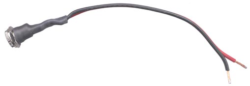 |
2.1x5.5 mm DC power jack to wire ends |
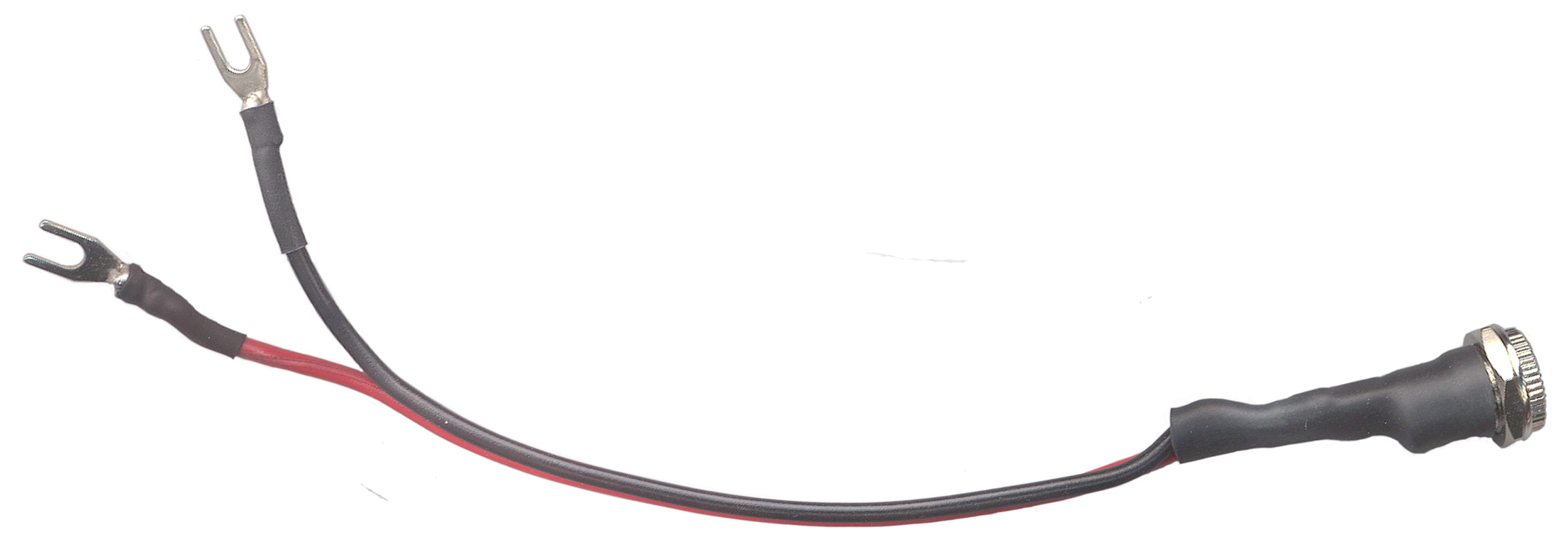 |
spade terminals to 2.1 x 5.5 mm DC power jack |
Related
Super Circuits P-38 (Mintron 63V5) Color Integrating Low Light CCTV Camera
Harbor Freight Color Security CCTV camera
KPC-350BH (Super Circuits P164C) Monochrome Low Light
Web Cam 2 - using in still image mode where an image is grabbed at some interval and the .jpg us uploaded to the server. Until the 4 input video card gets here only one camera at a time can be connected to the computer. My 2-way satellite connection has nowhere enough bandwidth to support anything like live video.
7" TFT Color Monitor
[an error occurred while processing this directive] created 4 Sep 2007