There are four separate printed circuit
boards in this camera.
Rear and Right boards

The rear board has all the rear panel controls soldered to it.
There are a number of connectors to get wires to the other
boards. Only the red and black power input wires are soldered.
The right board has a metal shield on the side facing the camera and on
the other side are a couple of transformers and a number of
electrolytic caps, so it looks like the AC/DC power supply that's
connected directly to the two input wires.
Left Board
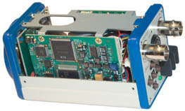
The
left
board
has large scale ICs on both sides and is marked MTV63V2
which is the model number of an earlier version of this camera.
There is a 9 conductor ribbon cable (plus ground(s)) to connects to the
front board. Some IC numbers:
Mintron M-92128B
6A A, 49323
0625PBM2
BA7665A
two IC SI IC41LV16100S-50TG, one of which has a sticker "63V5HN", so
maybe some type of ROM.
Front Board
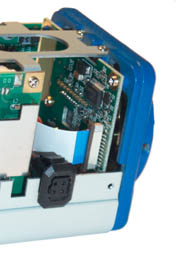
This board holds the CCD and one other IC (M88020). My guess is
that by changing this board you can made a number of cameras that
differ only in what imaging CCD is used. There is a hole in the
PCB directly behind the CCD chip so you can read some of the label
that's printed on the bottom of the IC (since the top is the open
side), which shows: 544XD, X408AK.
The CCD is the ICX408AK. But the Sony timing generator and output
amplifier chips have been replaced by Mintron custom chips on the left
PCB.
This board has a ribbon cable that connects to the left board and no
other connections to other boards.
The 4 socket connector is for an auto iris lens. The mating plug
comes with the camera.
Weatherproof Housing
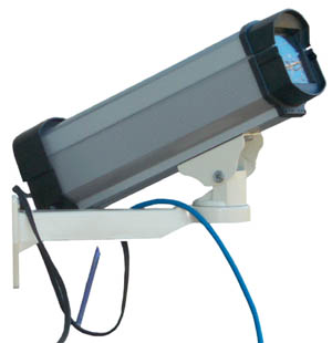
I've
mounted
the Mintron 63V5 in a
Super Circuits ENCOD weatherproof housing since it's starting to get
cloudy in mid Sep 2007. Since this is not a security camera I
mounted it low so I can sit in a chair to do any work needed. The
camera attaches to a sheet metal mounting plate using a supplied
1/4-20x1/4" stubby screw. For the 3-8 mm Varifocal DC auto iris
lens the front of the lens needs to be flush with the front of the
plate. You can just eyeball the left right rotation of the camera
to get it pointing straight out the window. The sliding sunshade
can only be out a small amount and stay out of the field of view.
Maybe a long telephoto lens would allow for more extension.
The rear black plastic end cap has two places to bring in wires, but
the holes are too small for a BNC connector or an RCA connector so you
can not easily install a ready made cable. I just cut a notch at
the bottom center to just clear the Siamese DC/Video cable (black) and
the CAT5 remote control cable (blue). This allows removing the
end cap completely which is good since you don't want any weight
on the cables trying to pull the camera and it's mounting plate out of
the housing.
When opening the rear cap it's easy to drop a screw into the
dirt/plants and loose it.
Also be sure to start turning the screw CCW until it drops into the
thread then turn clockwise. This has been working and the threads
in the housing are still fine after many cycles of the cap.
The mounting plate may be shorter than the slot allowing it to move
once the rear cap is installed. This can be a problem when a wide
angle lens is used since you will see the edges of the window if the
camera moves back. Also if there's any movement the RS-232 cable
may unplug.
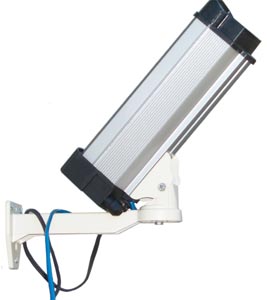
This is the maximum up angle you can get with the housing square to the
wall without inverting the mount. Notice that the cable pass
through nuts are straddling the mount arm so if the camera is panned to
the left or right the elevation will need to be lowered maybe 5
degrees. If the camera is panned past the cable nuts then it
might tip up another 10 degrees.
I used a twist & tie to hold the video, DC and Remote cables
together and to the base plate. Otherwise any pull on the remote
cable will unplug it since it's a DIN type push in with no
locking.
A single twist & tie was not good enough. It's necessary to
tie the
remote cable to the mounting plate in maybe at least 3 places so that
there's no way it can move and so that there's pressure pushing the
connector into the socket.
The Mintron 63V5 (Super Circuits PC-38) is sitting below the centerline
of the window. That's probably a good thing, but not sure
depending on the lens used.
17 Sep 2007 - After taking the above photo and starting to measure the
bracket and housing to see what adjustments can be made the key
adjustment was found. That's the rail under the housing allowing
it to be positioned anywhere along the length between the two end
caps. Now it's all the way forward and so can be tipped up
whereas now the housing is against the house wall.
The camera mounting plate may have 1/2" of fore and aft slop. To
keep the plate up front so the lens does not get vignetted by the
window
I used two tooth picks, one on each side, wedged between the mounting
plate and the groove it slips into.
Housing looks the same as the 3.5" x 3.5" x 13.5" DOTWORKZ SCH-13.
$49
at 123 Security Products,
$35
at Super Circuits (no label),
$49
at WebCamProShop
ENCOD2 Mini Outdoor Security Camera 6.75 X 3.5 H X 4.25 W Housing
$40
@ Super Circuits - I wonder if the longer ENCOD/DOTWORKZ SCH-13 can
just be cut to length with a hacksaw?
Remote RS-232 Operation

Note
Super
Circuits is selling the camera without supporting RS-232.
Learning what some of the settings do will be much easier if they can
be set from inside at night from the computer.
The 63V5 is specified by Mintron to have full setting and read back of
parameters by using RS-232 with the ACK/NAK protocol. Only TXD,
RXD
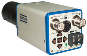
and GND are used. Since the AUX connector has 8 pins and
the in stock
CAT5 cable also has 8 wires that's what I used. The DIN plug
supplied
with the camera goes into the camera using the skinny pins and when you
look at the back of the connector it's the same as looking at the back
of the Mintron at the socket, so the pinout diagram in the manual works
as is for connector wiring.
15 Sep 2007 - The RS-232 remote is working and tonight I'll start
trying different settings. In the day time it's clear that a
gamma of 1.0 causes the trees to be very dark and gamma of 0.45 renders
them in a much nicer way.
Setup RS-232
The steps are:
- Make a cable according to the 63V5
Manual
- Download the free software
from
Mintron as a zip file and expand it (but do not run yet).
- At the computer end of the cable with the camera connected to the
other end and powered you should see -9 volts on pin 2 relative to
ground (pin 5).
- Be sure your COM port is set to 9600 8N1 (the common default).
- Run the software.
Troubleshooting
More times than it works, it displays error -1, error -1 then says
Serial Port is not connected and shuts down. The cable was
unplugged, see Weatherproof housing above.
Another error was "Camera Connection Changed (DR off) - caused by a
break in the pin 1-4-6 jumper at pin 4.
When checking RS-232 devices you should see a negative voltage between
the TXD pin from a device to ground. In this case with the
connectors separated -9 volts on the camera connector pin DB9-2 and -10
volts on the computer connector DB9-3. Both measured relative to
DB9-5.
The problem was with my cable. ALL the jumpers need to be
installed.
Setting
This camera has a very large number of
settings that are possible and they all can be accessed by either the
On Screen Display or by the RS-232 remote interface.
An advantage of this camera is it's great flexibility, but that's also
a problem since you need to know how to drive it.
My goal is to have a
24/7 web cam and
hopefully with no adjustments. In order to see stars at night the
Sense Up needs to be at the max of 128X. In order to work in the
daytime an auto iris lens that has a very wide range like f1.4 to f360
helps a lot. Also using what on other cameras is called
Automatic Electronic Shutter helps with daytime which is very bright
for a sense up type camera.
When AGC is OFF the daytime images are good but when it gets very dark
the screen turns solid black. AGC needs to be ON, but it's not
clear how to manually set Automatic AGC vs. setting a fixed Gain
level. In the remote programming commands it's straight forward
to enable Automatic Gain Control and that's what's wanted here.
The default is supposed to be Shutter priority AGC, not iris
priority. The latter is used for things like traffic cams or
where there's a lot of motion and you want the fastest shutter
speed. For astronomy where there is no fast movement and in
general using shutter priority is much better in terms of quality of
image. Once Sense Up X128 is selected, no sense up is used for
bright scenes. As it gets darker the shutter speed is slowed down
until it gets to 1/60 second and if more light is needed the AGC starts
using more and more Sense Up until it gets to 128X. I think after
this the lens gets opened up, but that's not clear.
While working on the remote control the AGC is ON and the LEVEL is at
half way. This may mean the camera iris DC voltage is at mid
range? I don't think so.
Some nights moving the AGC-ON Max slider results in not detectable
change in the image (after waiting 3 to 5 minutes for the camera to
recover from a black screen).
In the daytime switching the AGC between OFF and ON does not seem to
change anything.
The remote software confirms that there are three AGC settings:
- OFF
- AGC ON - The "Max" slider does not seem to do anything.
- MANUAL - level sets the brightness of the scene - this always
works the same way.
It may be that Sense really means Shutter and AGC means Iris, but I'm
still working on that.
?#1 Testing at night shows that with AGC ON the slider when full
left products a mostly black image. With the slider fully to the
right the image contains a lot of red fluffy artifacts. These may
be clouds since that's the appearance of clouds at night, or it may be
seeing related. In any case full up doesn't look that good.
But in the center gave the most pleasing to the eye result.
There are many hot pixels and in a still photo it's impossible to tell
which is a hot pixel and which is not. But in a time lapse movie
it's very clear since the stars are circling Polaris and the hot pixels
are just sitting there. It may be possible to make an overlay for
the VisionGS software that posts to the web that would black out the
hot pixels?
Satellites show up doubled, i.e. you see what appears to be two
satellites and a line drawn between them is on the path of movement
caused by the x128 (2 second) integration. In other cases a
bright dot appears and then goes away. Maybe caused by trees.
Related Equipment
KPC-350BH (P164C) Low Light Monochrome CCTV
camera
Harbor Freight Color Security CCTV camera
PC33C Color CCTV camera
7" TFT Color Monitor
WebCam2 - 24/7 Sky-Weather-Astronomy web
cam uploads new still image every 15 minutes. Oct 2007
start brighter than mag 4.5.

 The
left
board
has large scale ICs on both sides and is marked MTV63V2
which is the model number of an earlier version of this camera.
There is a 9 conductor ribbon cable (plus ground(s)) to connects to the
front board. Some IC numbers:
The
left
board
has large scale ICs on both sides and is marked MTV63V2
which is the model number of an earlier version of this camera.
There is a 9 conductor ribbon cable (plus ground(s)) to connects to the
front board. Some IC numbers:
 I've
mounted
the Mintron 63V5 in a
Super Circuits ENCOD weatherproof housing since it's starting to get
cloudy in mid Sep 2007. Since this is not a security camera I
mounted it low so I can sit in a chair to do any work needed. The
camera attaches to a sheet metal mounting plate using a supplied
1/4-20x1/4" stubby screw. For the 3-8 mm Varifocal DC auto iris
lens the front of the lens needs to be flush with the front of the
plate. You can just eyeball the left right rotation of the camera
to get it pointing straight out the window. The sliding sunshade
can only be out a small amount and stay out of the field of view.
Maybe a long telephoto lens would allow for more extension.
 Note
Super
Circuits is selling the camera without supporting RS-232.
 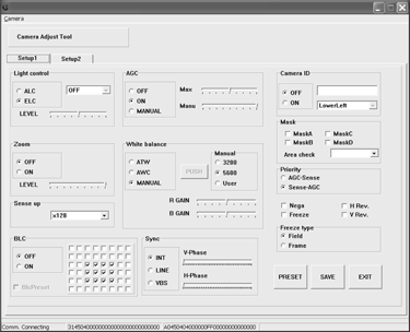 Software
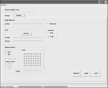 The
"Setup
2"
tab has less frequently used settings like High Light Set,
Automatic Peak Control (APC), Motion Detection. But also has the
Gamma selection 0.45 or 1.0 and the Color Bar generator On/Off.