RT-1694/PRC-138 HF Receiver-Transmitter
© Brooke Clarke 2013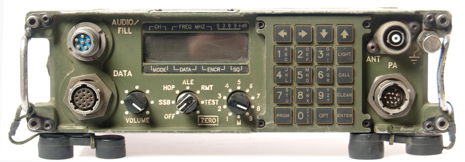
This is a modern Harris H.F. receiver transmitter and will fit into a large priority USPS mail box with room to spare.
The manpack version of this radio is the PRC-150 (Wiki). Known as the Multiband Falcon II radio by Harris, aka Falcon 5200.
VRC-150
Covers 1.6 to 59.9999 MHz (HF and VHF ranges, but not the full 30 to 88 MHz VHF low military band).
Output power levels: 100 mw (drive to external power amp), Low: 1 Watt, Medium: 5W, High 20 Watts.
Note: This radio is smaller than the PRC-25 or PRC-77. It uses the same dual 5590 type battery box as the RT-1319/PRC-113.
The radio powers up on 1600 kHz and it happens there's an AM broadcast station that's very weak there. Checked on my car radio and it's too weak there to understand, better on the PRC-138.
How many of these radios were made?
Model
NSN
A3
Data
Tones
RT-1694A(P)/U
5820-01-570-1982 Y
39
RT-1694B(P)/U 5820-01-433-1109 Y
1
RT-1694C(P)/U 5821-01-459-4711
39
RT-1694 D(P)(C)/U 5820-01-543-2842
5820-01-543-3993
5820-01-496-3523
39
RT-1694D(P)(C)/PRC-150??? 5820-01-495-6096
39
RT-1694(P) 5820-01-495-6096
39
RT-1694(P)/PRC-138 5820-01-544-0087
39
RT-1694A(P)(V)1/PRC-138 5820-01-417-5214
39
False leads:
5820-01-495-5029 WJ-8629A 20 to 2700 MHz
5820-01-495-5021 VXI-C 6U WJ-8721
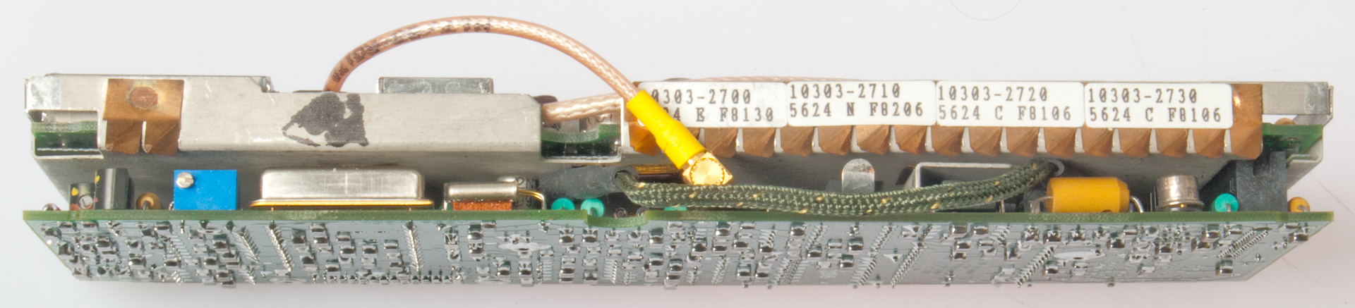
Here's some info on the boards for different versions, but not sure how this correlates to the above table.
This radio is a V2.
Version
A3
LPC & Voice
A4
CPU
A10
Front Panel
Top Firmware older V1
1313-2400 10313-2500 10303-2100 10372-8921,22,25 Later V1
10372-3440 10303-2500 10303-2100 10371-8926 V2
10372-3440 10530-2500 10530-2100 10530-8910
A3= 10372-3440-01 Rev (no change)
A4= 10530-2500-01 Rev (no change) "E42C" sticker on large chip.
PRC-138 Manpack
RT-1694, battery box, antenna, H-250 handset
20 Watt Vehicle
RT-1694 & RF-5030PA-20E Power Amp - Coupler, Whip antenna
125 Watt Vehicle
RT-1694 & RF-5032PA-125 RF Power Amplifier, RF-381 Antenna Coupler, Whip Antenna, RF-5056PS (for use with 12 Volt vehicles), RF-5055PS (AC to 24V power supply), RF-5051PS AC to 24V)
150 Watt Vehicle
RT-1694 & RF-5053PA-150 audio amplifier-speaker & RF Power Amplifier & RF-382 Antenna Coupler, Whip Antenna
This box mounts the radio without a battery box to form a combined radio-amplifier.
By installing or removing modules various options can be implemented.
A3 LPC Vocoder (RF-5161-01) can do analog voice encryption w/o A1A2
AlA2 Encryption (RF-5170) for digital voice or data encryption
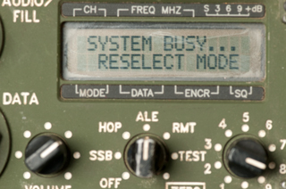
As received it was not possible to change out of SSB mode or change the frequency.
Doing that requires the security password (an eight digit number).
But after changing to 1k996 USB, 3k996 USB or 7k257 USB I'm getting HIGH VSWR messages.
A look at the web page for the TCI 651T antenna shows melted foam in the matching box, see photo:
http://www.prc68.com/I/Images/TCI651BalunHybb.jpg
I'm in communication with TCI to see about troubleshooting it.
11 March 2013 - the TCI 651 antenna may be fine. After installing a fresh LTC-7PN 3.5 V 750 mAh memory battery the radio tunes very quickly.
So the problem tuning may have been caused by lack of the memory battery.
In my car I can't hear any station on 1710 kHz, but on the PRC-138 with the TCI651T antenna there's a loud and clear station.
Password is commonly 24458300.
Self TEST
As I learn about the radio I've seen some strange behavior related to tune faults or VSWR measurements. Withe the mode switch TEST and TEST selected a Built In Test Equipment (BITE) test is run and the result appears and the back light is turned off. Pressing LIGHT clears the test result. It's as if they didn't want you to see the result.
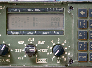
During a prior test the fault was A08-F51 now it's A08-F71
Module A08 is the RF Power Amplifier and Harmonic Filters.
The Fault # is in hex (51H or 71H) and represents the band numbers with a problem, in this case either:
51H = 0101 0001 or 71H = 0111 0001 or bands: 7, 5 & 1 or bands: 7, 6, 5 & 1.
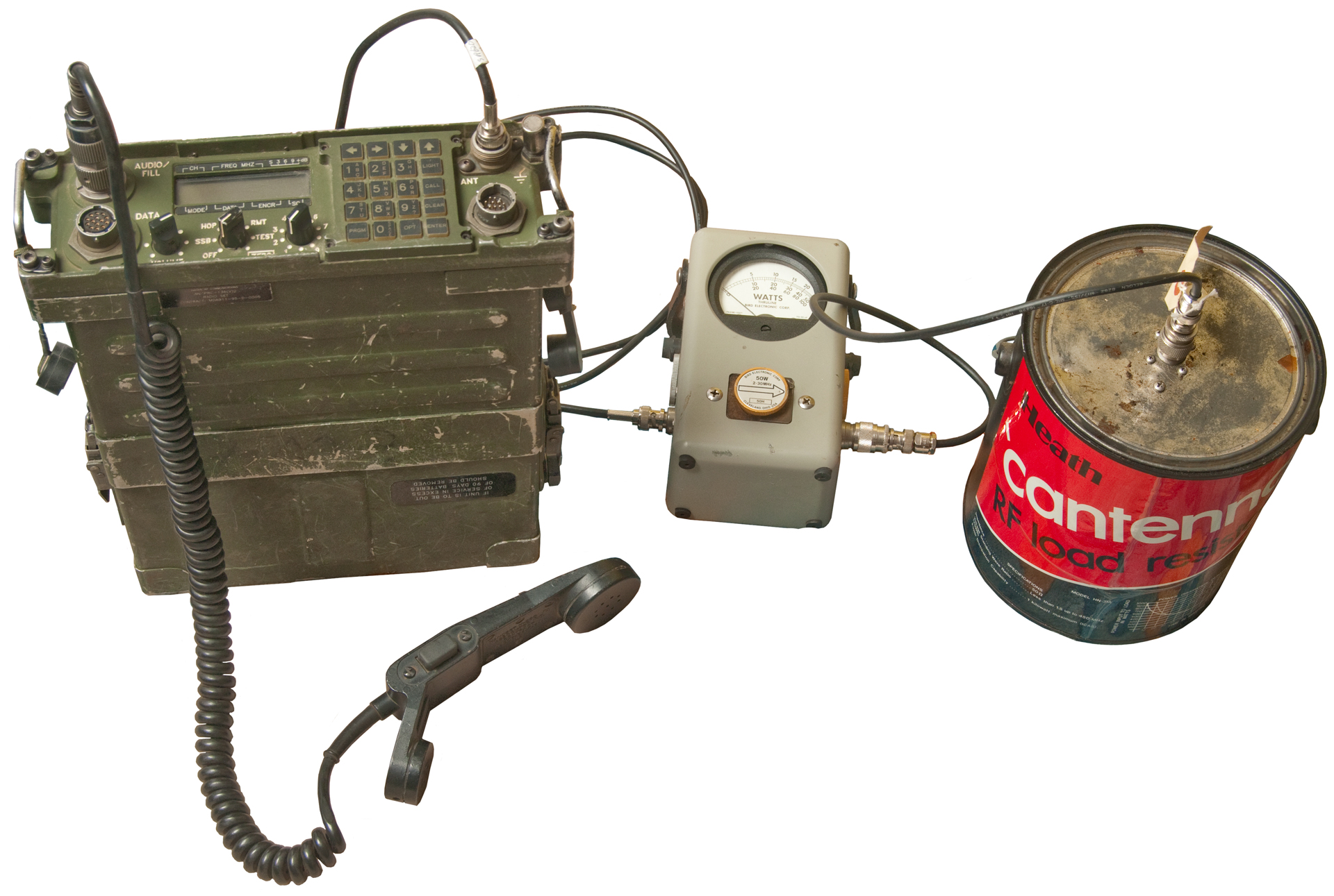
Power Out into a 50 Ohm Load
Another way to see if this is a problem with my TCI 651T antenna or with the radio is to test the radio with a Bird Power Meter and 50 Ohm Load (Heathkit Cantenna).
By selecting one of the programmed channels, pressing PTT and making a lot of noise into the mike (with no mike input there is no RF output for SSB modulation, and only a small amount of output for AME. The best way would be to key in CW mode or a data mode where you would get 100% power.
But, in any case, there were tune faults using the matched load, so this confirms that there's a problem with the radio.
See the ALE section below (and scroll down for the spectrum plot) where there's no sounding signal on 40 meters. The 50 Ohm load setup shows a tune fault on the 40 meter output.
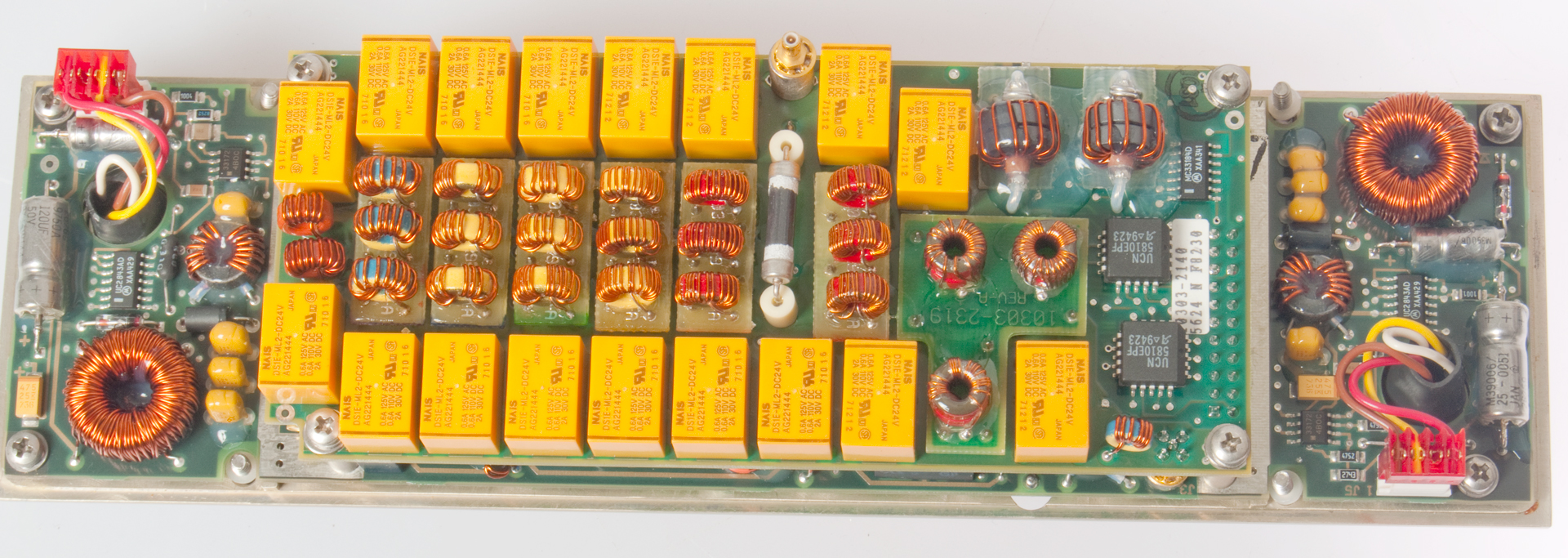
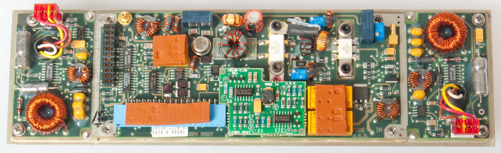
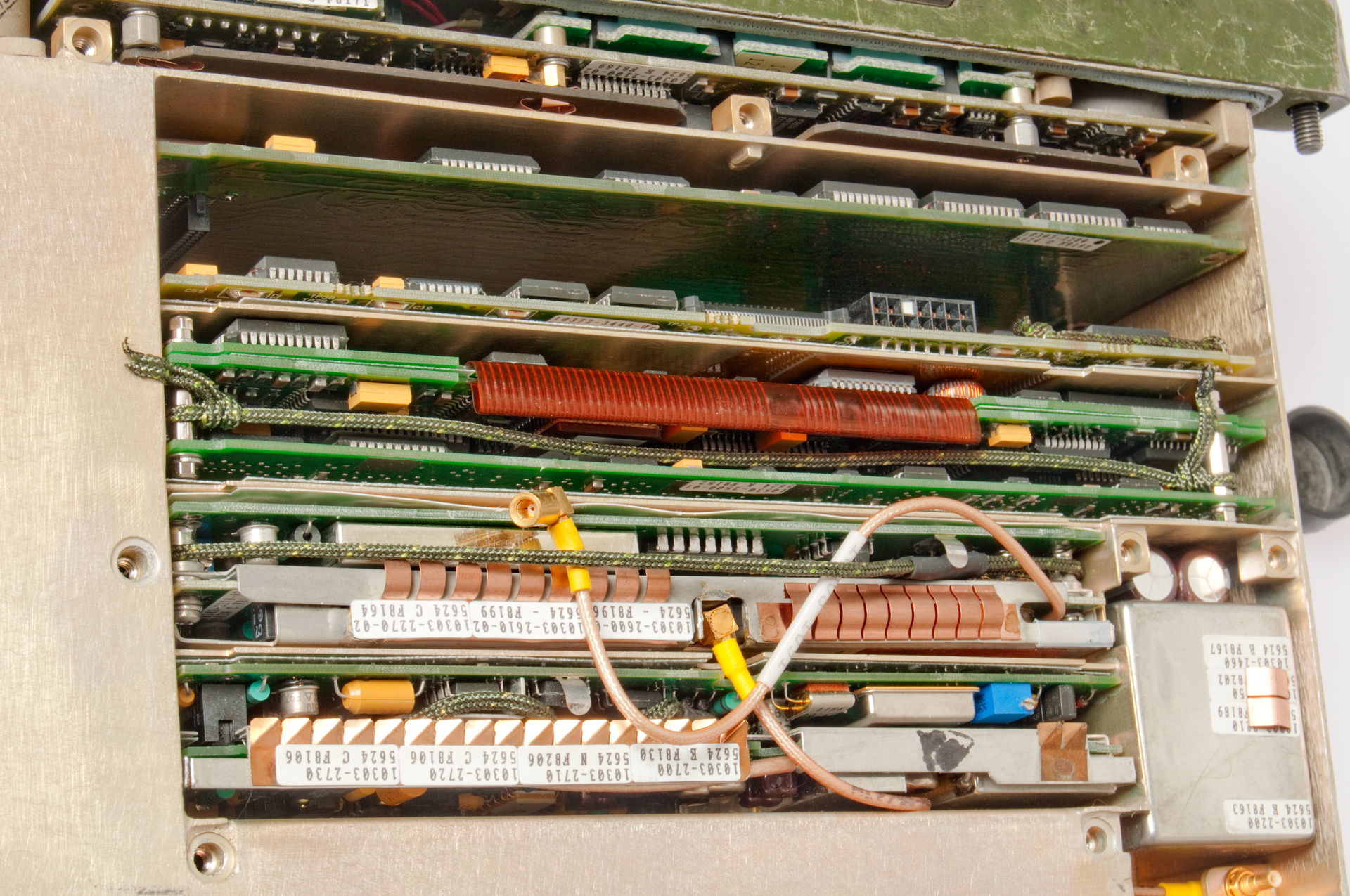
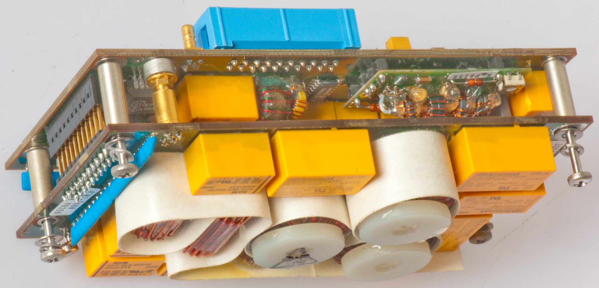
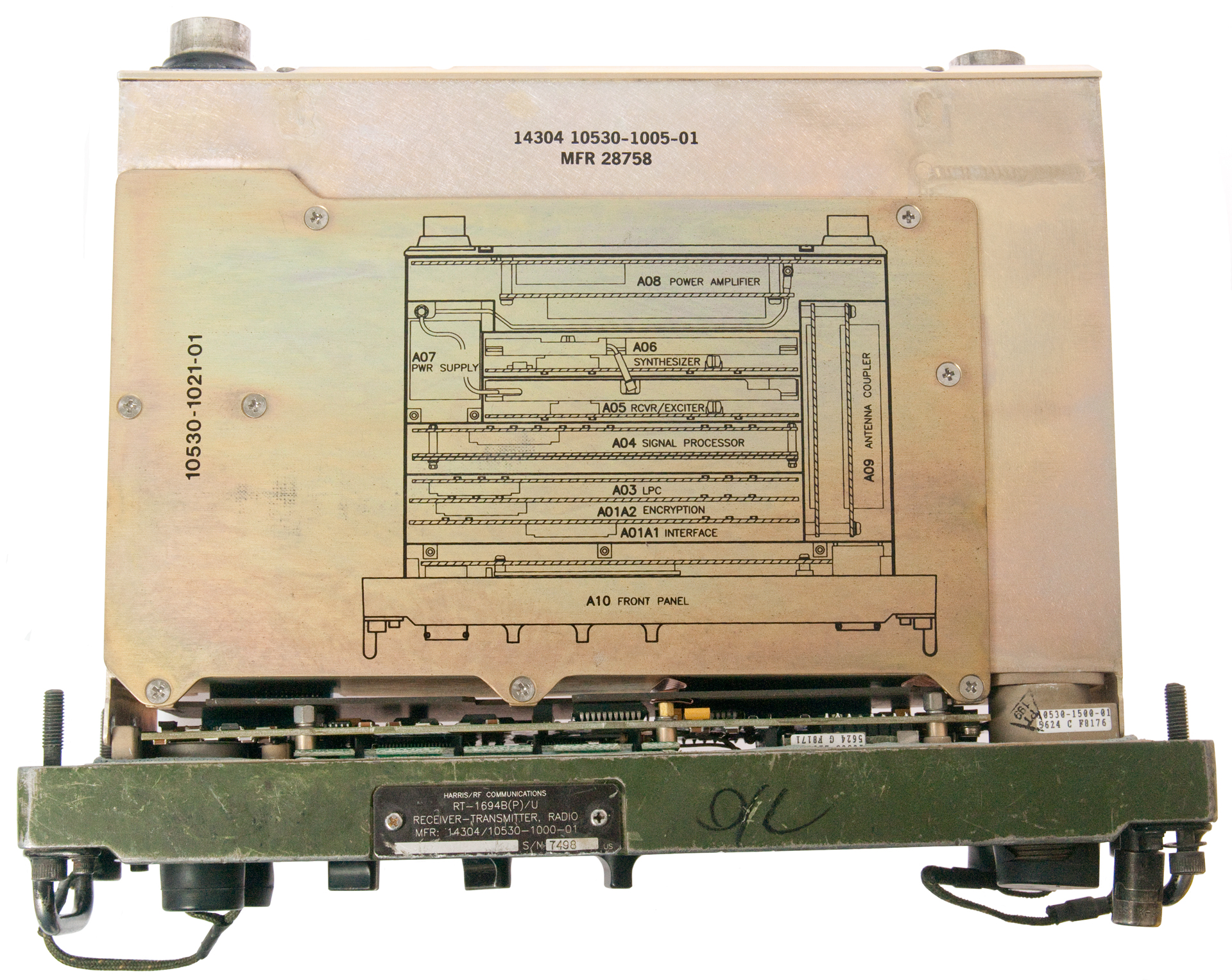
A8 Assembly
The A8 assembly has a number of functions
- 2 Battery Chargers (one for each battery) that use 10 - 32VDC external power
- Tx RF Power Amp - either 100 mw or up to 25 Watts output
- Band Filters for transmit harmonics or receive preselection
- Receive preamplifier
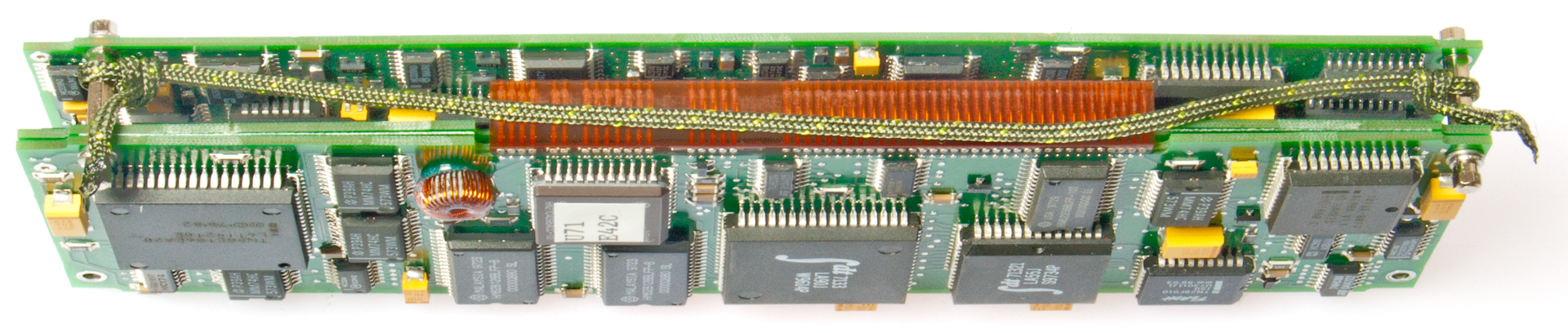
A8 complete assembly
The A2 top board has the harmonic filters and their relays
A8 (A8A2 Harmonic board removed)
On the left and right are the battery chargers.
In the center is the RF power amp.
The relays are: DS1E-ML2-DC24V (Mouser data sheet)
They are SPDT latching with 2 coils (Set * Reset) 6 pins.
The big resistor in the center of the harmonic filter board should be 50 Ohms.
But it measures a dead short. This is normal because it's shorted out by a transformer.
By energizing relay K17 the 50 Ohm resistor can be measured and is 46.6 Ohms 7% low is OK for 10% spec).
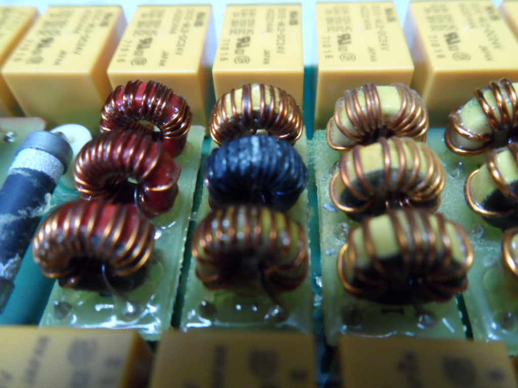
Photo from Mike Murphy - Bad Coil
Coil between K7 & K8
Band 4: 4.9 - 7.75 MHz
L11: 0.963 uH
But . . . is that really the problem?
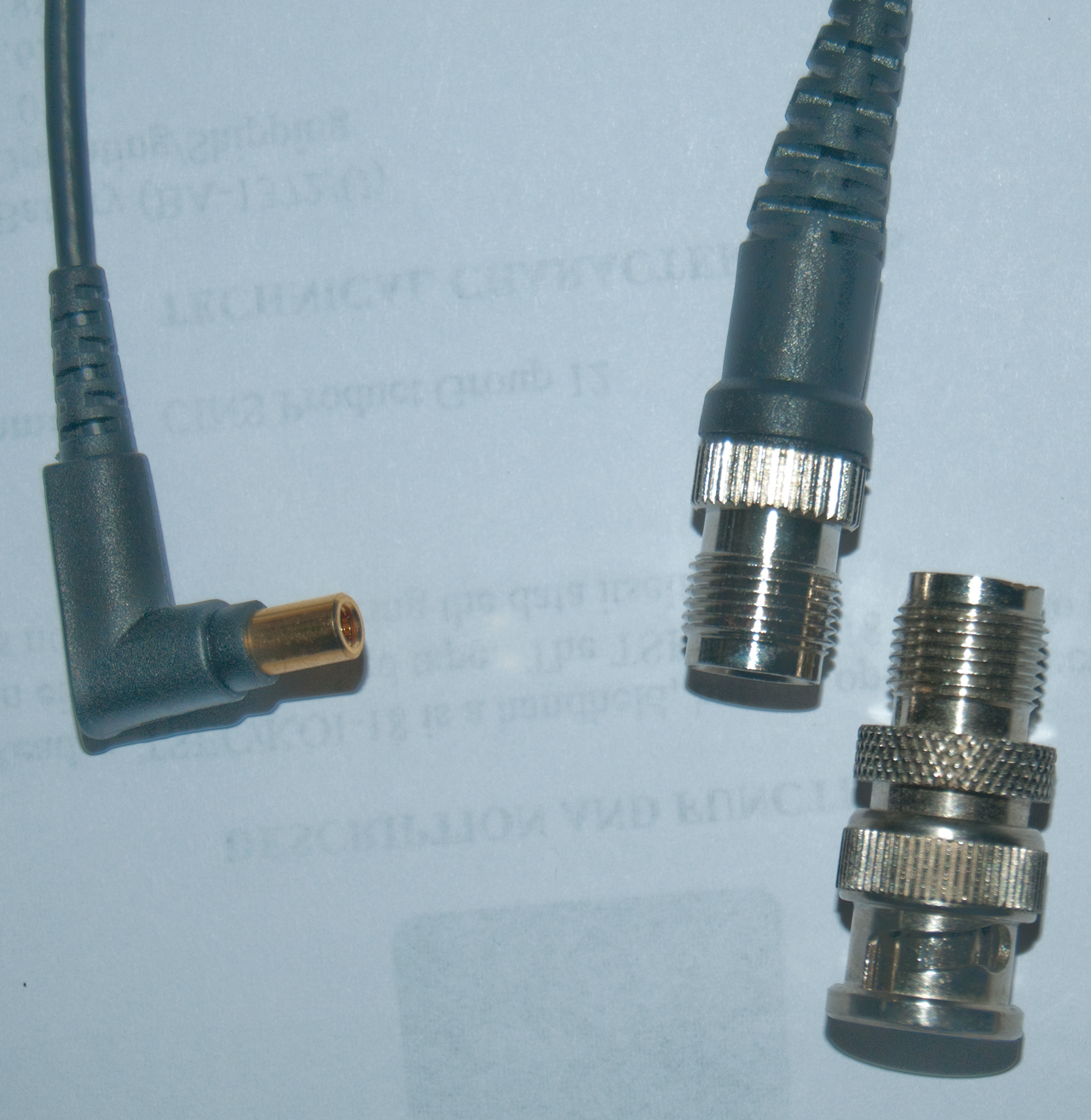
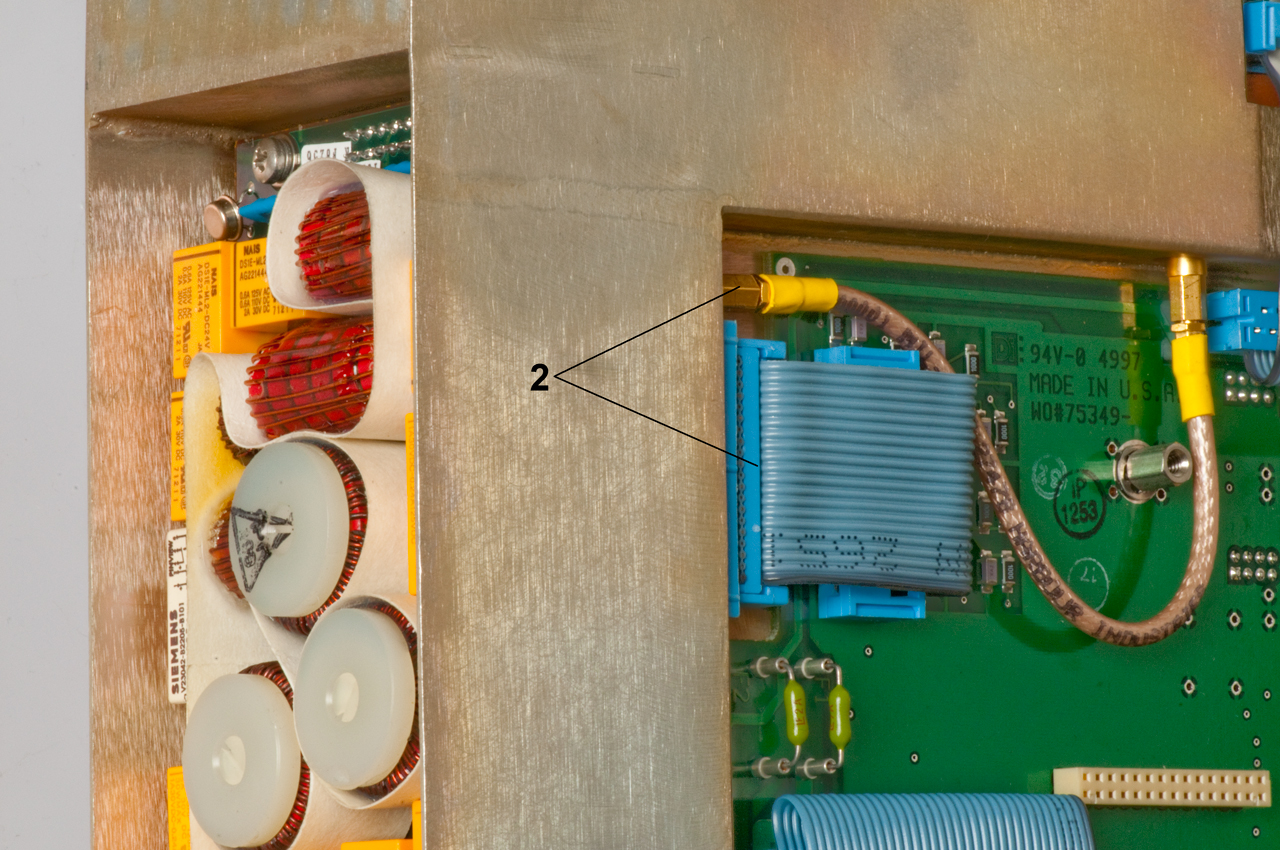
Small Coax & Test connectors
Plug on cable, jack in lower right of photo. Jack goes
to A8 RF In/Out from/to A5 Exciter.
The coax connectors may be SSMB or1.0/2.3 Snap-on.
I have adapter cables on order from eBay 16 Mar 2013
Note: Using SSMB adapters will not work because in some places the SSMB connector is close to a PCB and the adapter
diameter is too big to fit.
18 March 2013 - I've heard that these are SSMB connectors
so one of the cables that's on order should work.
Another neat idea is to solder a short wire to a test point so
that you can monitor it without using board extenders.
If the connector type was known board extenders could be made.
2021 May 5 - they may be just 1.27 x 1.27 oin headers (Wiki)?
Block diagram (click on image for larger version)
SSMB to TNCf cable
TNC to BNC adapter for scale.
Harmonic Filter Bands
Pass band frequency in MHz. Bold are bands with fault.
Band
Pass
Stop
Relays
1
1.6 - 2.0
3.2 - 6.0
K1, K2
2
2.- 3.14
4.9 - 9.42
K3, K4
3
3.14 - 4.93
7.75- 14.79
K5, K6
4
4.93 - 7.75
12.2 - 23.25
K7, K8
5
7.75 - 12.16
19.1 - 36.5
K9, K10
6
12.16 - 19.1
30 - 57.3
K11, K12
7
19.1 - 30
47 - 90
K13, K14
8
30 - 60
110 - 180
K15, K16
The most likely problem would be bad relays.
----or-----
The problem is in the A9 Antenna Coupler.
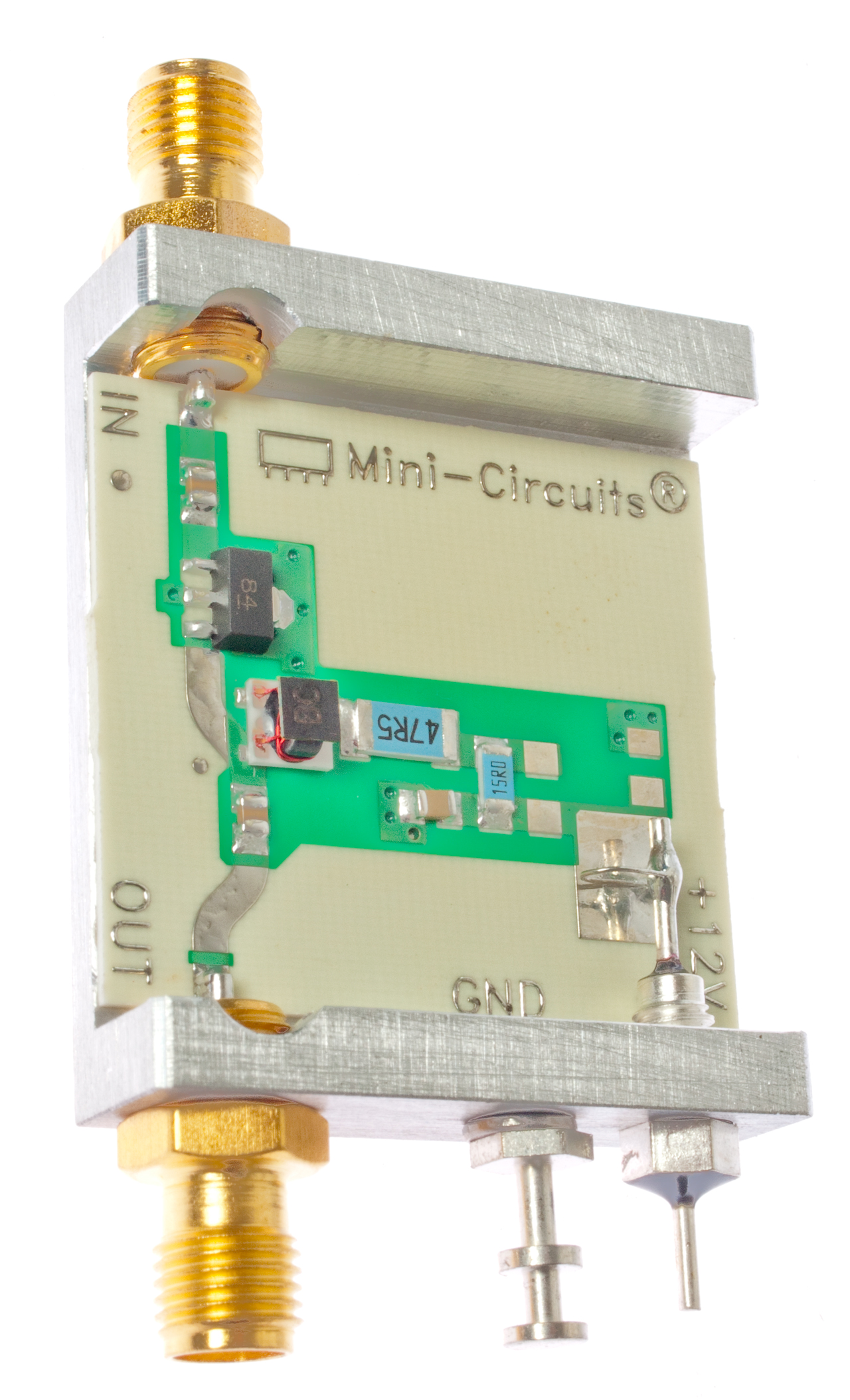
Idea for an RF amplifier
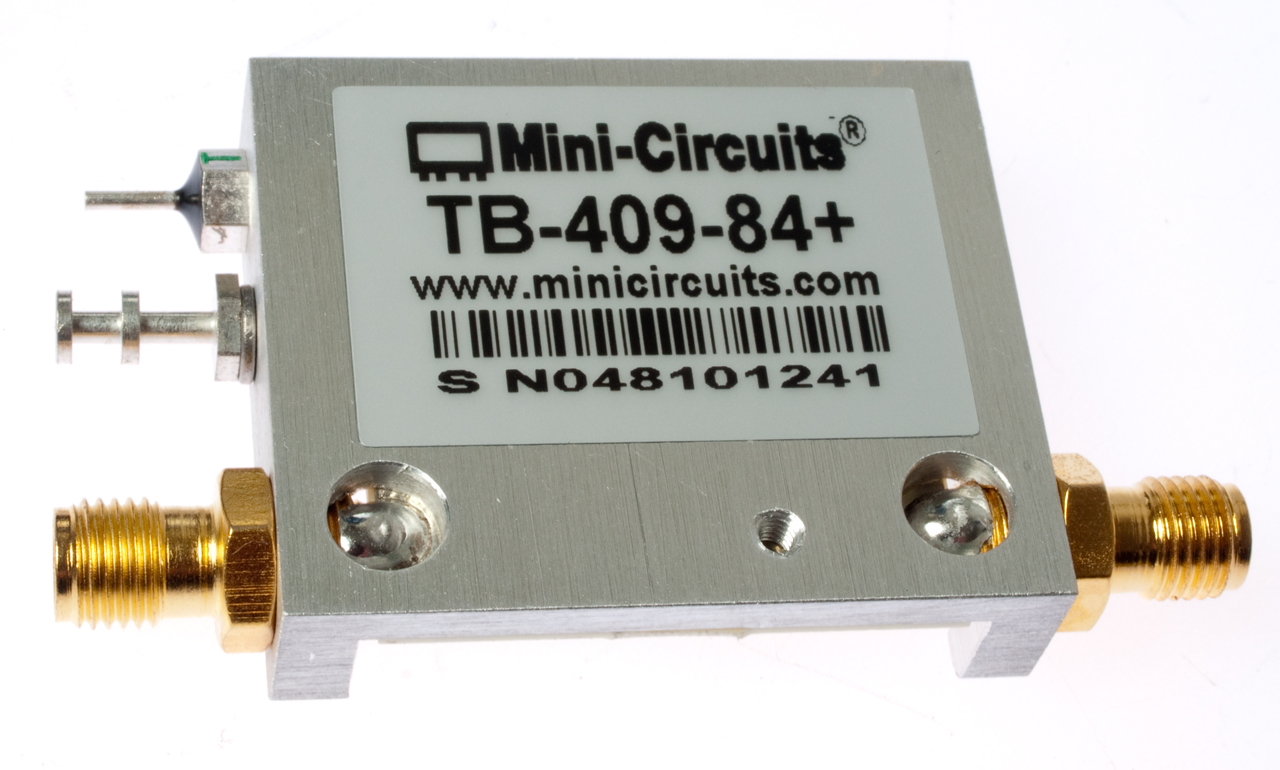
Minicircuits makes an IC RF power amp (GALI-84+) that's very broadband. The TB409-84+ RF Amp Evaluation kit has the IC mounted with the needed components with SMA connectors. DC to 6 GHz, 25 dB gain, >+20 dBm output. Could be used to replace the A5 amplifier or as the front end of a power amp.
Troubleshooting
The A8 module was removed and the harmonic filter board separated (re-seated).
All the other boards were re-seated as well as the ribbon cables.
Channels 21 through 27 were programmed at the geometric center of bands 1 to 7 in CW mode.
Tests done with output to Bird power meter then Cantenna, see above.
Three tests were done:
Test 1 - regular settings (coupler enabled, 20W ant port auto, high power)
Test 2 - coupler bypassed, 20W ant port BNC, high power
Test 3 - coupler bypassed, 20W ant port BNC,low power (Power too low for Bird meter to measure)
The test sequence was:
In SSB mode, Ch M, select channel <enter> key handset and wait for stable result
While keyed read power on Bird meter, release PTT
Switch to TEST mode and select VSWR
Note: the frequency defaults to the last transmit frequency and Tx mode
press <enter> record indicated power and VSWR
switch back to SSB and repeat for each channel.
The "Watts" column comes from the VSWR test display. There's a firmware bug in that it displays 20 Watts when the output is full power, even if the radio is running in a lower power mode where the max output power is much lower.
Chan
Band
Freq
kHz
Test 1
Test 2
Test 3
Po
VSWR
Watts
Po
VSWR
Watts
Po
VSWR
Watts
21
1
1788
13
1.3
20
18
1.2
20
-
1.2
20
22
2
2506
20
1.1
20
21
1.2
20
-
1.2
20
23
3
3934
13
1.3
10
16
1.1
20
-
1.1
20
24
4
6181
TF
TF
15
11
1.1
16
-
1.1
16
25
5
9708
2
3.1
6
2
1.0
2
-
1.0
2
26
6
15240
1
1.9
2
1
1.0
1
-
1.0
1
27
7
23937
1
4.5
1
1
1.0
3
-
1.0
3
The power seems to be decreasing rapidly with frequency. I would expect it to be above 20 W at all frequencies.
Maybe a bad RF power amplifier?
----------------------
Exciter
By running the radio in low power and with the harmonic filters disabled (the broadcast band high pass and the 60 MHz low pass enabled) the exciter can be analyzed.
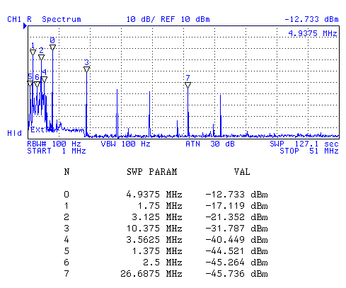
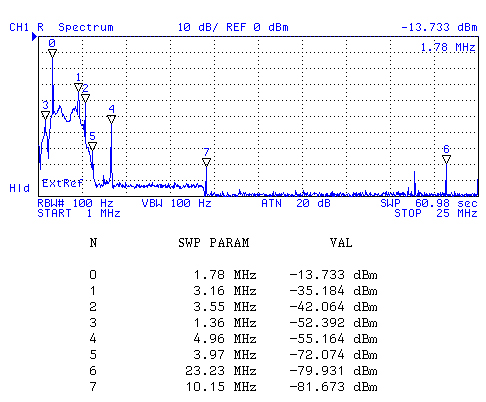
These spectrum plots were made by connecting the radio output directly to the spectrum analyzer 50 Ohm input ( input attenuator set to 30 dB).
I think the fundamental output should be 50 mW?
Rx Sensitivity with preamp disabled and IF BW at 350 Hz. Signal from HP 8648A Sig Gen.
Coupler Disabled
no pad
Coupler Enabled
20 dB 10W pad
Rx
Sens
dBm
Med Pwr
mW
(gain)
CE
Radio in receive mode, looking at what comes out the antenna BNC connector.
There's probably a 25 MHz crystal running.
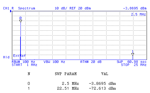
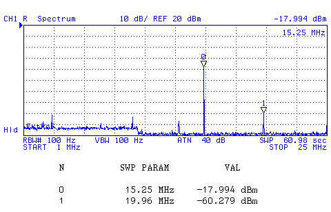
Fund @ 1.788 MHz: -17.119 dBm = 0.019 mW
Fund @ 1.788 MHz: -13.7 + 20 = +6.3 dBm = +4 mw (23 dB more w/coup)
-130
10 Fund @ 2.506 MHz
Fund @ 2.506 MHz: -3.8 dBm + 20 = 16.2 dBm = 41.7 mW (close to spec)
-130
40 Fund @ 3.934 MHz
Fund @ 3.934 MHz: 0.5 dBm + 20 = +19.5 dBm = 89 mW (close to spec)
-126
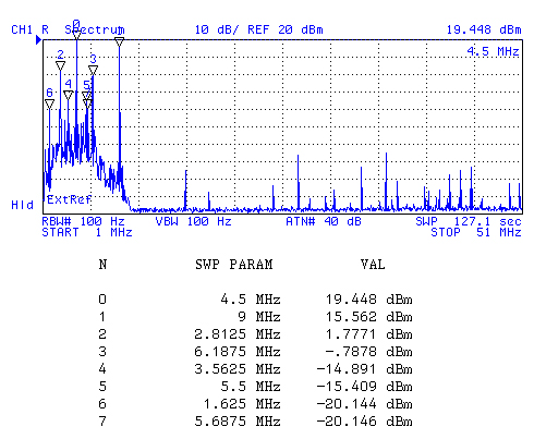
89 Fund @ 6.181 MHz: -0.8 dBm = 0.8 mW
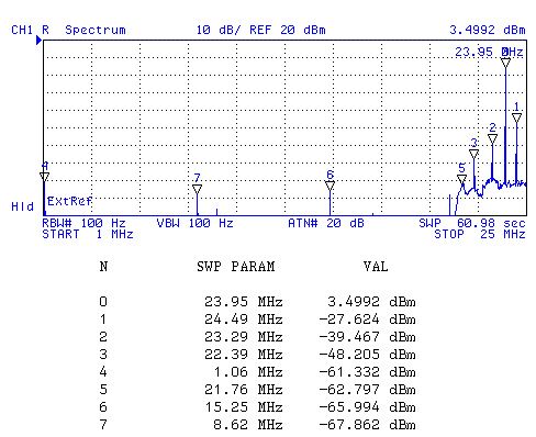
BUT . . there are signals at 4.5 & 9 MHz at +19 & +16 dBm.
Fund @ 6.181 MHz: -2.6 + 20 = +17.4 dBm = 55 mW (close to spec) (18 dB more)
Note: this was the only frequency heard when ALE sounding.
-120
123 Fund @ 9.708 MHz: -13.19 dBm = 0.048 mW
Fund @ 9.708 MHz: -10.3 dBm + 20 = +9.7 dbm = 9.3 mW
-128
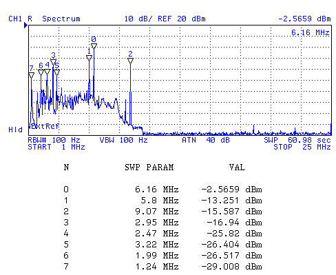
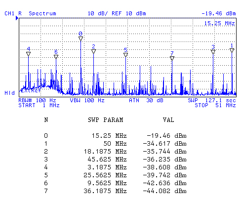
630 Fund @ 15.240 MHz: -19.46 dBm = 0.011 mW
Fund @ 15.240 MHz: -18 dBm + 20 dB = +2 dBm = + 1.6 mW
-121
1000
Fund @ 23.937 MHz:
Fund @ 23.937 MHz: +3.5 dBm + 20 = +23.5 dBm = 224 mW (in Spec)
-127
1584
Summary of Fundamental Power (mW)
Remeasured with 20 dB pad (why different from spec an direct input?)
Freq
kHz
Low Power
Medium Power
Gain dB
L->M Pwr
Coupler Disabled
Coupler Enabled
Coupler Disabled Coupler Enabled C Dis
C Enab
1788 11
11
2
10
-7
-0.4
2506
40
42
40
40
0
0
3934
88
89
110
90
0.1
0
6181
120
55
290
123
19
3.5
9708
520
9
650
630
1
18
15240
600
2
1100
1000
2.6
27
23937
830
224
1800
1600
3.4
8.5
Ideas
By using SSMB male and female test cables along with standard BNC cables it would be possible to:
Measure A9 Antenna Coupler
This can be done as either a full S11, S21, S12, S22 test or as just a transmission test.
Measure A8 RF Power Amplifier & Harmonic Filter
This can be done as either a full S11, S21, S12, S22 test or as just a transmission test.
Measure Exciter/Receiver
This can be just a power out test or also include a receive sensitivity test.
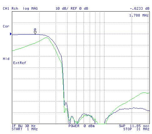
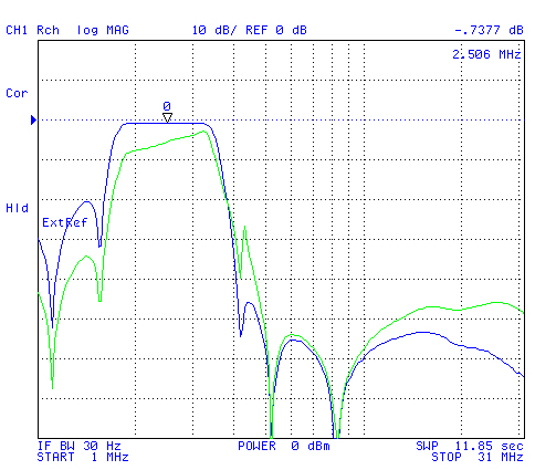
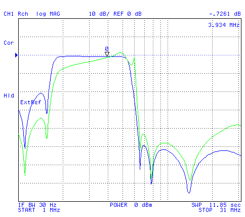
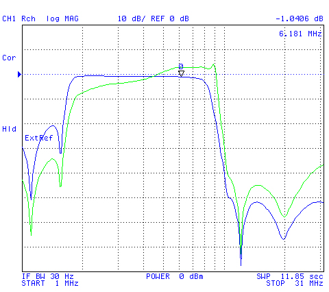
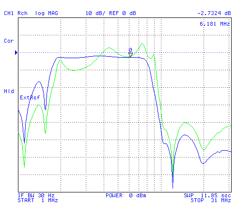
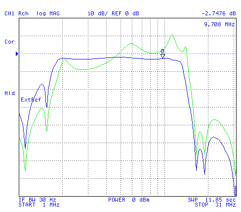
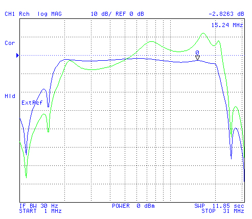
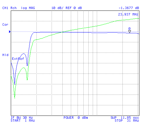
Measure between A5 Exciter/Receiver and Antenna BNC in two directions (Low Power)
BNC cable from HP 4395A Network Analyzer goes to SSMB adapter cable then to A8 Amplifier-Power Amp.
BNC cable from PRC-138 ANT connector goes to "R" receiver on network analyzer.Note: in receive mode the RF Amp is bypassed so you see only the harmonic filters.
When the radio is keyed the RF amp is switched in (low power mode) and so you see it's gain curve, which is pretty much the same in the filter pass-band.
Note the receive path gain (blue) is flat in the pass-band and is around -3 dB
The Tx gain (green) should be in the 10 to 20 dB area, but is near zero.
It looks like the harmonic filters are working fine but either the A9 Antenna Coupler or RF amp has a problem
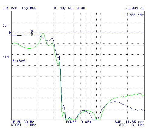
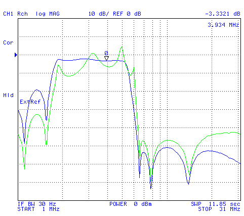
Next to repeat these tests with the coupler disabled.
The Rx preamp is bypassed in both the following tests.
Conclusion:
The harmonic filters are working fine.
The low power Tx amp does not have enough gain and is low at the lower frequencies
Something in A8 near Q5, Q4A, Q4B.
The adjustments on R36, R48 & R55 might show where the problem is.
That requires supplying power with current monitoring. A couple of 5590BA battery adapters (two to support the radio), but with a bench power supply instead of batteries.
The Q4 & Q5 transistors are not the problem because they are for the 25 Watt power level.
When Low Power is selected the 100 mW (+20 dBm) signal comes directly from the A5 exciter module.
The A5 module uses U3, U1 & Q5, U2, T1 to generate the 100 mW signal.
Chan
Fc
kHz
Rx (green) & Tx (blue) Gain
A9 Ant Coupler bypassed
Rx (green) & Tx (blue) Gain
A9 Ant Coupler active
1
1788
2
2506
3
3934
4
6181
5
9708
6
15240
7
23937
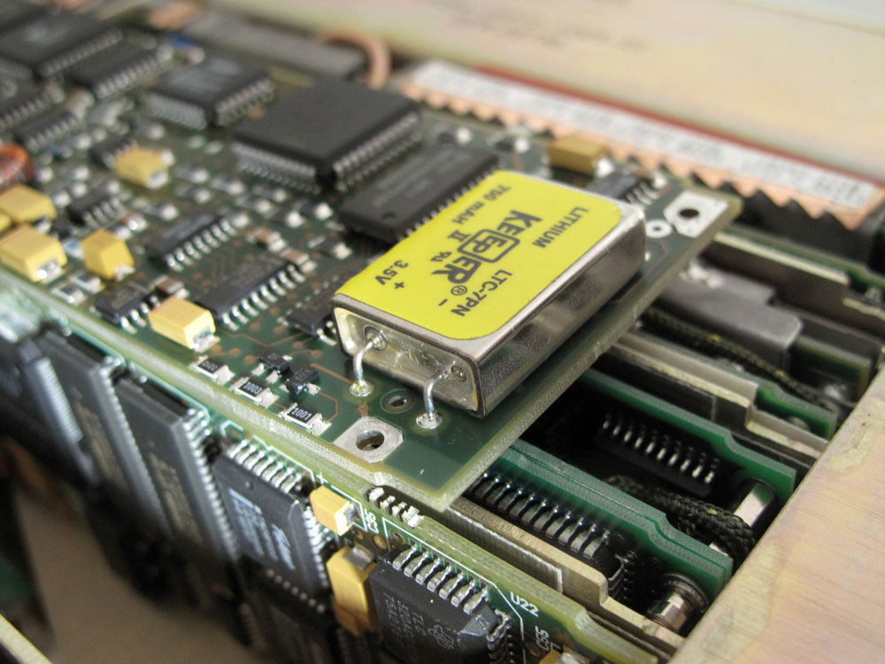
Internal Memory Battery
When this battery fails the radio will not remember setup information so it will need to be entered every power up.
Also see the A01A1 Interface Board below.
LTC-7PN 700 mAh 3.5 Volts
Note: Do not use a socket.
Sockets result in poor electrical connections after some years, so will decrease the reliability.
See: What Goes Wrong
What Went Wrong
It's been suggested that my antenna may be a poor match and that caused this problem. But I don't buy it because the radio has VSWR sensing and power reduction when it sees a poor match. That's very important for a radio that covers 1.6 to 59.9 MHz where no single antenna is likely to be a good match across all those frequencies.
The radio showed Tune Faults when initially trying to use it and after replacing the dead memory battery it started to tune.
BUT . . . .
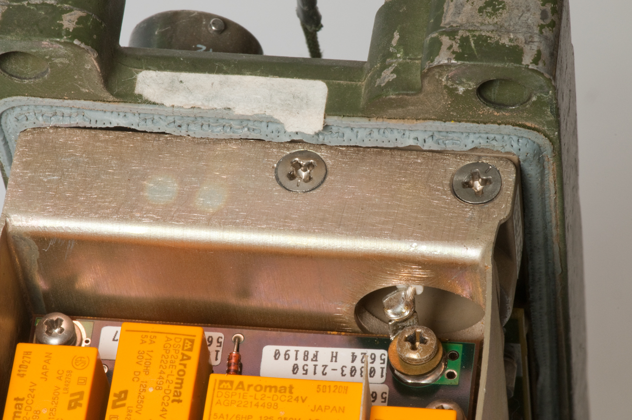
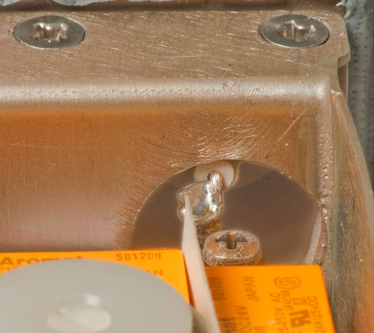
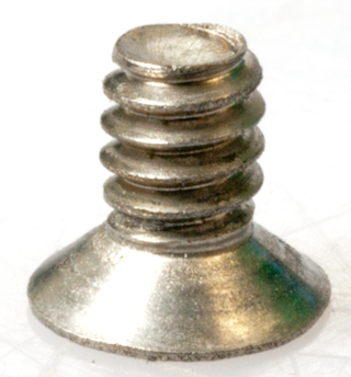
In the process of replacing the memory battery (the first time the radio had been opened up) a couple of screws that hold the chassis to the front panel were seen to be missing.
They were later found on the carpet and replaced. (At no time did I hear them rattling around.).
After replacing the memory battery that antenna coupler started working, see Operation above. The reason may be that the memory battery is needed for the antenna couple to work and/or it may be that the two loose screws were shorting out some part of the antenna coupler. Note the two screws are adjacent to the antenna coupler circuitry.
This doesn't help much in troubleshooting, but does shed some light on what went wrong.
Missing Screws when radio first arrived
Different view of screws & Antenna Terminal
Seems that the hot antenna wire is very close to ground.
One of the screws showed a very fine metal shaving,
but it doesn't show up in photo.
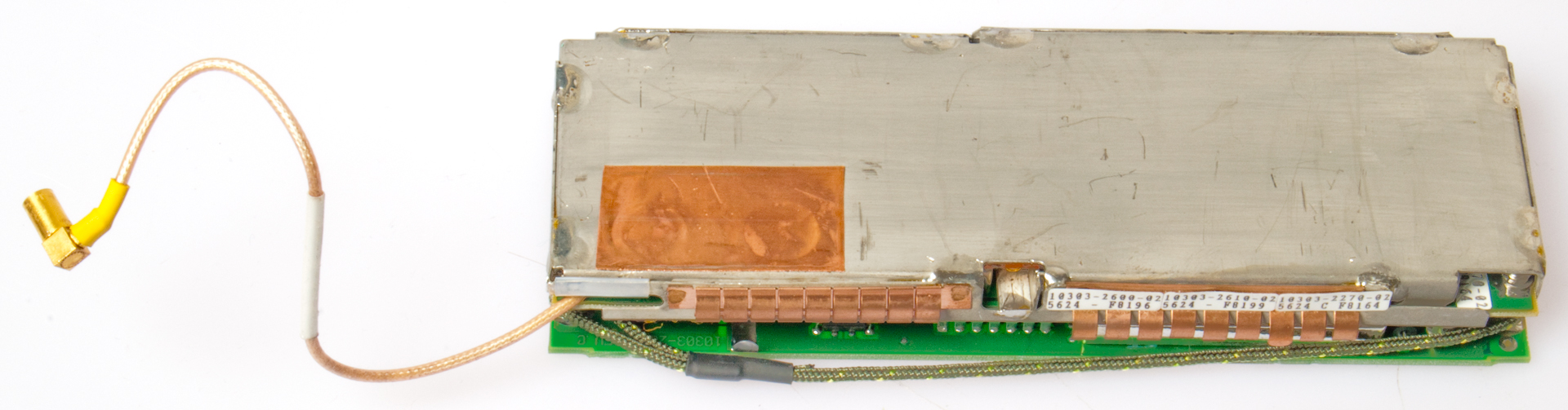
A9 Coupler Assembly
To remove the A9 Antenna Coupler:
1. Remove the brass screw holding the antenna connection terminal.
2. Remove the ribbon cable and SSMB coax connection on the bottom of the chassis.
3. Loosen the 4 captive screws holding the A9 board and remove.
The daughter board in the upper right is the VSWR
sampler.
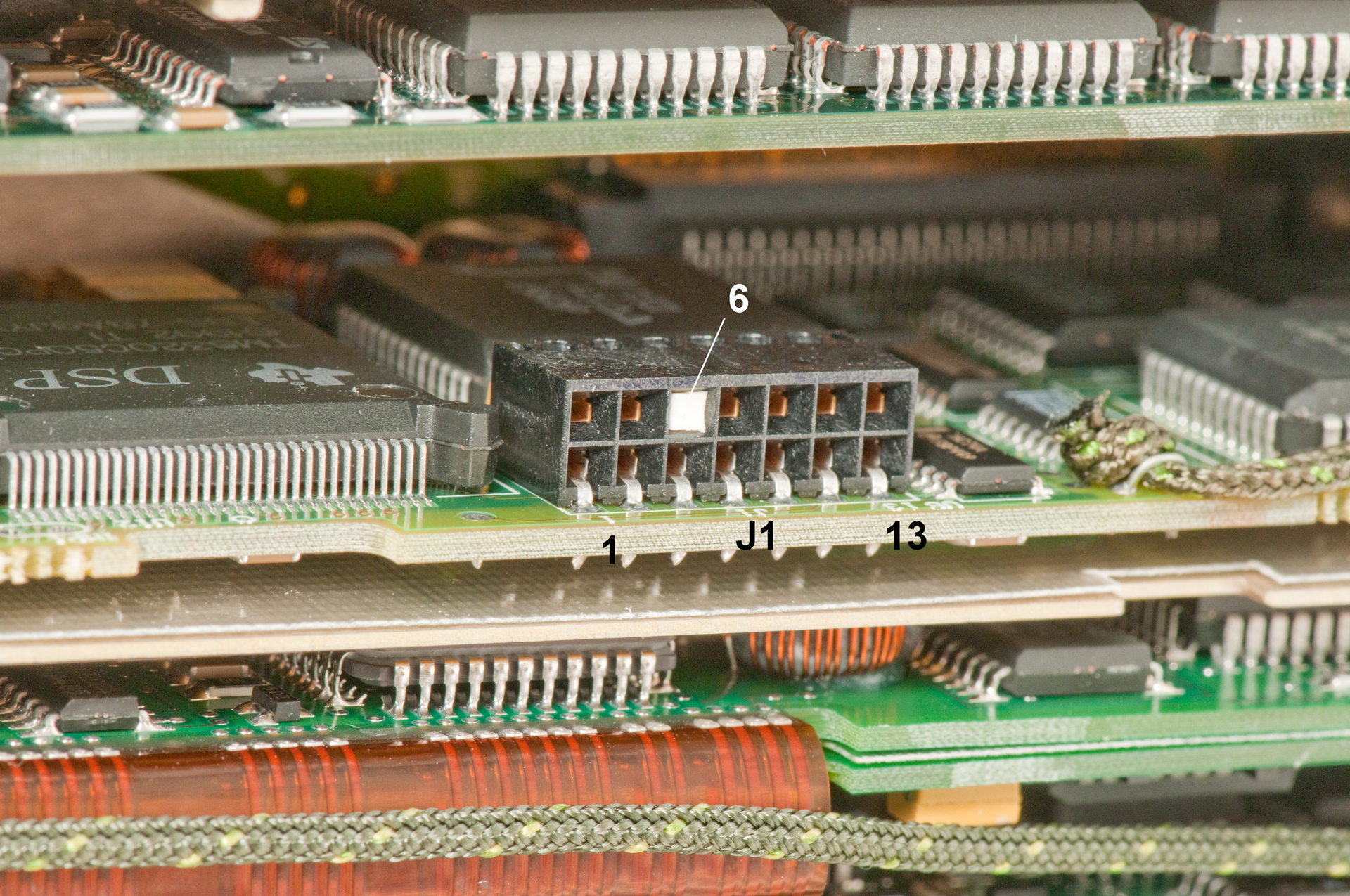
A1 Interface & Encryption
A2 ? not assigned
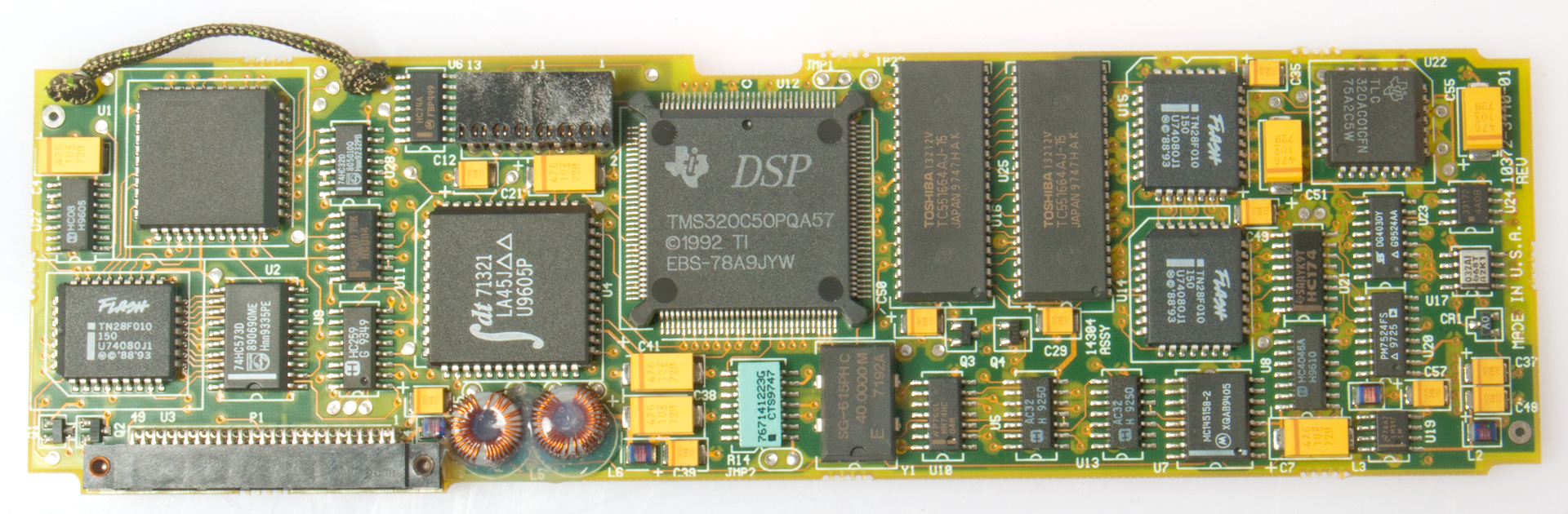
A3 Linear Predictive Coding, Voice & JTAG
The JTAG (Wiki) connector in next to the TMS320C50 DSP chip.
The TMS320C50 DSP chip has it's JTAG terminals wired to only J1, not to any other place in the radio.
Boundary Scan (Wiki)
The TI TMS320C50 (data sheet page 33) includes a JTAG 1149.1 boundary Scan Test-Access Port (TAP)
But the TMS320C50 DSP chip is wired to U1 a TN83C51FB which has Port 1 directly on the P1 connector.
Port 0 is the mux data/low order address and Port 2 is the high order address byte (Intel mux data & address scheme)
It has 16k EPROM and 256 bytes of RAM.
U4 is an IDTIDT71321 Dual Port High Speed 2k RAM with one side connected to the TMS320C50 DSP and the other to the TN83C51FB using the address and data buses of each IC.
- debugmode - Felix Domke
JTAG Test Connector
the big IC to the left of J1 is the TMS320C50
JTAG (Wiki) Test Connecter A03-J1 (black)
Pin
Sig
JTAG
Pin
Sig
JTAG
1
+5.025
TMS
2
0
Gnd
3
+4.837
TDI
4
0
Gnd 5
+5.069
+5
6
white plug
Gnd 7
-0.037
TDO
8
0
Gnd 9
+5.025
TCK
10
0
Gnd 11
+5.025
TCK 12
0
Gnd 13
+5.006 EMU0
14
5.013
EMU1
TMS: Test Mode Select
TDI: Test Data In
TDO: Test Data Out
TCK: Test Clock
EMU0: Emulation pin 0 used for high speed
EMU1: Emulation pin 1A3-J1 JTAG connector
black 2x7 with white pin
SourceForge - JTAG -
http://www.gojtag.com/ - 4 April 2013 package on the way.
http://www.goepelusa.com
"Boundary-Scan Test: A Practical Approach" by Bleeker, Harry on order 31 March 2013
A4 Signal Processor
A5 Receiver/Exciter
The A5 board has an SSMBf coax cable hard wired that goes to a male-male connector mounted to the chassis. The other side of this connector is a loose female-female cable (10372-1053-61) that goes to the A8 RF Power Amp. There is another coax cable between the A8 Power Amp and the A9 Antenna coupler.

P1 2x10 Pin Connector (needed for extender board)
A5 Receiver/Exciter 2x10 0.050" pitch socket
A6 Synthesizer

A7 Power Supply
A8 RF Power Amplifier
See BITE Fault A8
A9 Antenna Coupler
See BITE Fault A9
A10 Front Panel
The DATA connector has pins for two different functions. Sending commands to the radio and receiving it's status and/or sending and receiving data using the modem function of the radio. A Y cable could be made to allow both of these functions to be done at the same time. The remote control panel from a 5000 series Harris radio can be connected to the command & control serial port at this connector.
Remote control is by means of an ASCII terminal or program sending and receiving ASCII commands, or a Harris 5000 series hardware remote panel.
Remote Cable
Marked:
10372-9868-06
Remote Cable
Harris RF Comm.
CAGE 14304
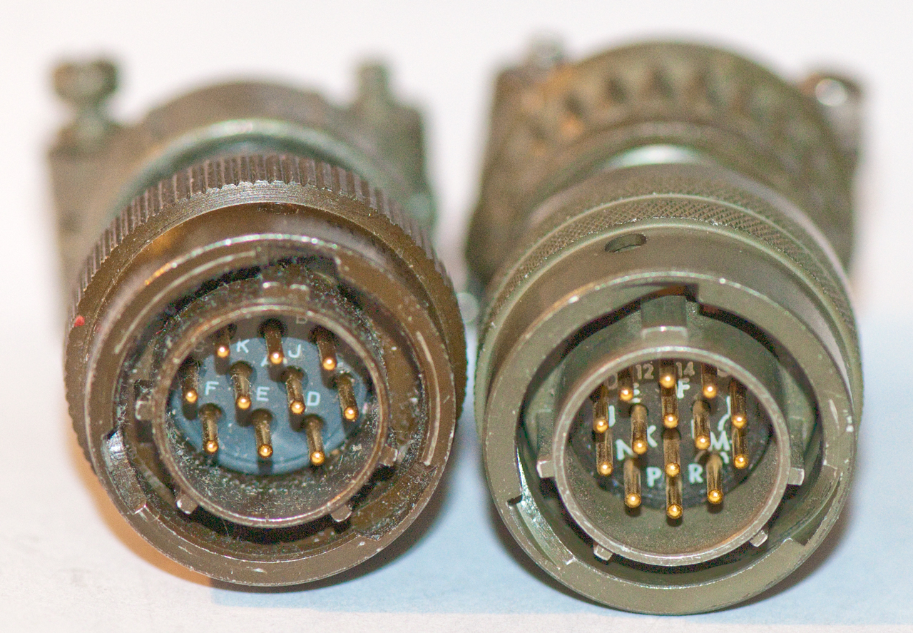
The computer end is a DB-9f and the radio end is a PCI U-316/U 14 male pin 3-lug mil connector.
A connector that mates to the radio DATA port in addition to the U-316 is the PT06 12-124 & m-f threaded adapter & 3057-6A cable clamp. (available from William Perry)
Comparison of two PT06 connectors.
On the left is the 10 pin connector that fits the PRC-25 & PRC-77 POWER connector.
On the right is the 14 pin DATA connector for the PRC-138.
Remote Cable
Wiring
DB-9
Wire
U-316
Rx
2
Orange
N
Tx
Tx
3
Red
K
Rx
Gnd
5
Brown J
Gnd
nc
1 4 6
7 8 9
L
CTS
P
RTS
Because of the way the cable is made (nothing connected to DB-9 pins 1, 4, 6, 7, 8 or 9) there is no hardware flow control.
But the radio uses RTS/CTS (pins P & L on the U-316 but there's no jumper between them, so there's a problem depending on how the radio asynchronous port is configured.
Checking the radio SSB \ Config \ Ports \ Remote: changed from 2400 to 9600 baud, but left others at default: 8N1 Xoff/Xon flow control, Echo: On.
There is no option for RTS/CTS, so is this cable supposed to work with the RT-1694/PRC-138? ans. the RTS/CTS is used when talking to the data modem in the radio, not sending commands to the radio.
The Falcon software requires direct access to the serial port and so will not work in WIN XP.
There are a couple of ways of getting into DOS. In both these cases you need a real serial COM port. The use of a USB to Serial adapter is problematical.
- For newer computers you can install a bootable version of DOS on a USB thumb drive along with the Falcon software files and boot from that.
This requires a BIOS option to boot from a removable media- For older computers you can install a bootable version of DOS on a floppy or CD-ROM along with the Falcon software files and boot from that.
OFF
Probably not really power off, but rather very low current standby.
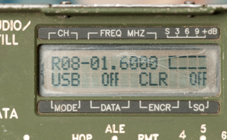
SSB
This is really not Single Side Band mode, but rather single channel mode - defaults to USB.
The single channel can be USB, LSB, AME, CW or FM
Modern car radios go up to 1710 kHz so there are a number of channels that this radio might talk to?
WARNING: Trying to transmit below 2 MHz using the man portable whip will damage the radio.
HOP
Frequency Hopping
ALE
Automatic Link Establishment - not yet programmed
There is an amateur radio ALE protocol. See the:
HF Link Yahoo group
11 March 2013 - my TCI 651T antenna works for receive, but not transmit but maybe I can listen to ALE sounding?
The TCI 530 is a log type antenna pointing up, would be excellent for ALE since I live in a canyon in the mountains (about 1,000 ft elevation).
Wish list of antennas: TCI 530 (takes a 300' square) or 545 antenna (takes an 85' square) please let me know.
12 March 2013 - the radio is sounding on the HFN net. More tomorrow after it's collected some data.
Settings (for sounding only, not for voice nets)
Channel Group: 0
Channel Group: 1
Channel List: 9, 10, 11, 12, 13, 14, 15, 16 (the HFN frequencies in USB)
Channel List: 9, 10, 11, 12, 13, 14, 15, 16 (the HFN frequencies in USB)
Self Address: GCE, N6GCE
Individual Address: 123
Net Address: (none)
LQA for N6GCE: Interval: 01:00, Time: 18:44 (clock not set)
(no LQA for GCE)
Configuration
Channels to scan: 008
Listen before transmit: On
Key to call: Off
Maximum Tune Time: 15 sec
Radio Silence: Off
Link to Any Calls: Yes
Link to All Calls: Yes
Auto Display Messages: Yes
----------------------------------------
after a day running ALE sounding in the lower right was "M1" meaning one message.
01/02/92 05:38 From: KK7IF -> KK7IF Las Vegas, NV
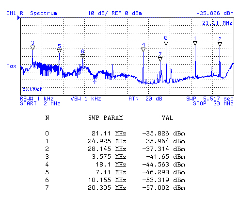
As a check on the Tx output while sounding the HP 4395A was setup in spectrum analyzer mode scanning from 2 to 30 MHz with RBW at 1 kHz and a wire about 5 feet long connected to the input. Max Hold mode. Here's the plot:
Table of HFN frequencies:
HFN
kHzMarker
Mkr kHz
3596.0
3
3575
7102.0
5
7110
10145.5
6
10155
14109.0
?
?
18106.0
4
18100 21096.0
0
21110
24926.0
1
24925
28146.0
2
28145
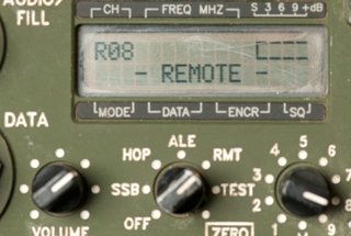
RMT
Remote Control (can use RF-5000 remote).
It's based on a serial data connection like RS-232 or MIL-188 using Xon/Xoff.
There's a floppy disk with FALCOM.EXE and other files.
Let me know if you have a copy.
I
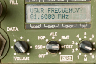
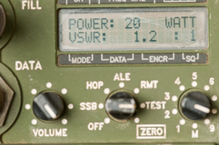
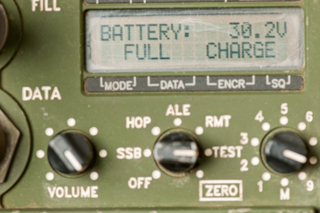
TESTThere are four sub modes: Test, Version, VSWR or Battery
Use the arrow keys at the top of the keyboard and the ENTER key to navigate the menus.
Note: An H-250 handset and the TCI TCI-651T antenna are connected for these photos.
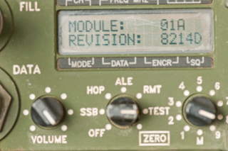
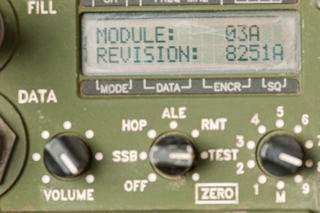
TEST
Version
Version
Version
Version
VSWR
VSWR
Battery
ZEROThis is the mode to erase all the programming. It feels like there's a stop preventing the switch from going to the ZERO position.
The knob must be pulled out to clear the stop that prevents accidental zeroing.
The "NO" is flashing. Pressing the up or down arrow changes it to YES.
Pressing ENTER zeros the radio.
LIGHT has been pressed then OPT (option)
Left & Right Arrows (<- & ->)
These keys are used to move between menu items.
NOTE: in some menus there are more items that can be displayed so the last item is ->.
You MUST scroll right (->) in order to see those off screen items.
In a similar manner you need to use the right arrow key to see all of a message that's too long to fit on the screen.
Up & Down Arrows (^ & v)
When a menu item is blinking if you press ENTER you will set the item to the current value.
When a menu item is blinking if you press Up or Down the item will change values.
NOTE: This is not intuitive so do try up and down on blinking items to see what happens.
LIGHT
There are two functions (the same independent of the mode switch):
LIGHT: 7 levels from [MIN] to [MAX]
CONTRAST: 7 levels from [MION] to [MAX]
CALL
Call only works when the mode switch is at ALE.
The top level menu is:
CALL: Auto, Manual
Individual/Net, All, Any
CLEAR
The function of the CLEAR button does not depend on the mode switch, but does depend of context.
When in any of the menus pressing CLEAR is like pressing RETURN, it takes you up one level in the menus or if in the top menu takes you out of program mode.
When entering data CLEAR works as a destructive backspace. For example to enter a message containing CA (for California) the A and C letters are both on the 1 key so after getting C displayed you need to press some other key to "set" the C, say you press 9. Now pressing CLEAR erases the 9 and you can press 1 the press 1 again to get A.
ENTER
This is a classical ENTER key used to accept the current variable.
OPT - Option
The function of the option key depends on the mode switch position.
The top level choices are shown below.
SSB
RETUNE, POWER, TIME, SCAN (enable/disable), BFO
HOP
TIME, POWER
ALE
LQA, SCORES, TIME, POWER, RETUNE, EOW-TO, TX_MSG, RX-MSG
RMT
n.a.
TEST
n.a.
PRGM - Program
The function of the program key depends on the mode switch position.
The top level choices are shown below.
SSB
CHAN, DATA, CFIG, SECUR
under CFIG you can set the TIME.
To change the date a remote terminal is needed.
HOP
NET, EXCLUDE, DATA, POWER, SECUR
ALE
CHAN_GRP, ADDRESS, LQA, CFIG, SECUR
RMT
n.a.
TEST
n.a.
RF-5960 Master Code Programmer
Can program the radio or the RF-5961 loader.
RF-5961 Field Code Loader
Needs to be filled with the RF-5960.
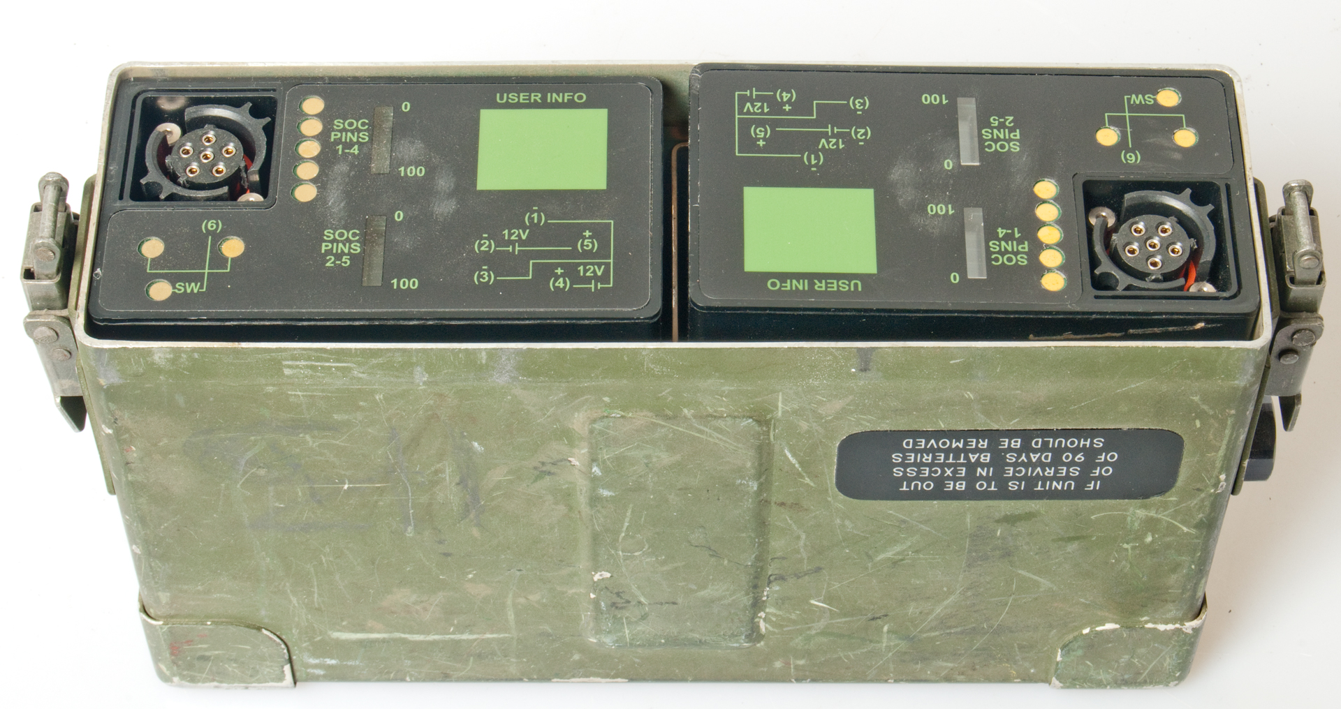
Battery Box: Harris p/n: 10513-4800-02 or p/n 10372-1300 (fits PRC-150, PRC-138, PRC-113, RF-5800, etc)
I'm using a couple of BB-2590 batteries and charging them with the PP-8498/U.
The RT-1694 has a jumper between battery terminals 2 and 4 so is using each battery as a "24 Volt".
But there are no hard jumpers between the two batteries.
The radio can be operated with a single battery but that will result in reduced output power and shorter talk time.
The radio can use any of the BA-5590 family of batteries.
Inside bottom of RT-1694.
The two fuses are marked 7A.
Battery box from PRC-113 and
a couple of BB-2590 batteries.
When channels are programmed they do not survive power off so the memory battery probably needs to be replaced.
Top
Bottom A8 to A9 coax cable SSMBf - SSMBf
With top cover removed.
Upper left SSMBf coax from A5 in this photo to A8 hidden.
Need SSMBm connector to measure exciter RF output power
or connect to other side of SSMBm-SSMBm panel mount jack.
A01A1 Interface Board
Big ICs:
S9330AB
U19 Z8523010VEC - main controller
U34 Z8523010VEC - AGC
88C681J
FLASH TN28F010
10181-8017 Harris ROM?
LTC-7PN Battery 3.5 V 750 mAh (measures 0.6 V)
Military
TM
Title
Harris
p/n
Title
10181-0034-01 20 Watt Pwr Amp RF-5030PA-20E 10299-0349-01A 125 Watt Pwr Amp RF-5051PS-125 10225-0086-01 125 Watt Pwr Amp RF-5032PA-125E 10515-0005-4300 150Watt Pwr Amp RF-5033PA-150 10515-0006-4200
RF-5200 Falcon Series Manpack Tactical Communication Systems Operations Manual
10515-0007-4300 RT-1694 10515-0008-4300 RF-382, CU-2397 Antenna Couplers 10515-0009-4300 Power Supply RF-5055PS AC/DC 12-22 Amp output (@ Harris)
10515-0010-4300 Power Supply RF-5056PS 12V to 24V Converter
AS-2259/GR NVIS Antenna and NVIS in General
AT-1011/U aka Shakespeare 120 HF Antenna
BC611 BC-611 SCR-536 HF Radio set Signal Corps
CubicR3030 Dual VLF-HF Receiver
Electronics
AN/GRC-109 HF Set (Spy, Special Forces)
706 ICOM 706 ham radio
HF Propagation
PRC-104 HF Receiver Transmitter & MT-
PRC-47 HF Transceiver
PRD-1 HF Direction Finding Radio
RCS-5A RCS-5A HFChirp Sounder Receiver
Micom 2 HF Radio, Motorola Mobat
RF3200ET Harris RF-3200ET Portable Transceiver
SORAK Special Operations Radio Antenna Kit OE-452/PRC Five Configurations HF through VHF coverage
TW100F/AT Transworld Datron Fly Away HF Radio
Wire Antennas with TCI 651T
From the FCC data base.
KGST       AM 1600 kHz DAN  Daytime         B B LIC  FRESNO                   CA US      BL-19810507AC       5.0   kW   38453      LOTUS FRESNO CORP.
KGST       AM 1600 kHz DAN  Nighttime       B B LIC  FRESNO                   CA US      BL-19810507AC       5.0   kW   38453      LOTUS FRESNO CORP.
KAHZ       AM 1600 kHz DAN  Daytime         B B LIC  POMONA                   CA US      BL-19850228AH       5.0   kW   61814      MULTICULTURAL RADIO BROADCASTING LICENSEE, LLC
KAHZ       AM 1600 kHz DAN  Nighttime       B B LIC  POMONA                   CA US      BL-19850228AH       5.0   kW   61814      MULTICULTURAL RADIO BROADCASTING LICENSEE, LLC
KTAP       AM 1600 kHz ND2  Daytime         D B LIC  SANTA MARIA              CA US      BL-19890228AG       0.47  kW   6142       EMERALD WAVE MEDIA
KUBA       AM 1600 kHz DAN  Daytime         B B LIC  YUBA CITY                CA US      BL-20040106ABV      5.0   kW   56365      RESULTS RADIO OF CHICO LICENSEE, LLC
KUBA       AM 1600 kHz DAN  Nighttime       B B LIC  YUBA CITY                CA US      BL-20040106ABV      2.5   kW   56365      RESULTS RADIO OF CHICO LICENSEE, LLC
KAHZ       AM 1600 kHz DA2  Daytime         B B APP  YORBA LINDA              CA US    BMJP-20040130AAB     10.0   kW   61814      MULTICULTURAL RADIO BROADCASTING LICENSEE, LLC
KAHZ       AM 1600 kHz DA2  Nighttime       B B APP  YORBA LINDA              CA US    BMJP-20040130AAB     20.0   kW   61814      MULTICULTURAL RADIO BROADCASTING LICENSEE, LLC
NEW        AM 1600 kHz ND2  Daytime         B B APP  LEMON GROVE              CA US     BNP-20040129ARH      0.25  kW   160822     CHRISTYAHNA BROADCASTING, INC.
NEW        AM 1600 kHz ND2  Nighttime       B B APP  LEMON GROVE              CA US     BNP-20040129ARH      0.25  kW   160822     CHRISTYAHNA BROADCASTING, INC.
KTAP       AM 1600 kHz ND2  Nighttime       D B LIC  SANTA MARIA              CA US      BL-19890228AG       0.026 kW   6142       EMERALD WAVE MEDIA
KAHZ       AM 1600 kHz DA2  Daytime         B B APP  YORBA LINDA              CA US    BMJP-20100504ALA      7.5   kW   61814      MULTICULTURAL RADIO BROADCASTING LICENSEE, LLC
KAHZ       AM 1600 kHz DA2  Nighttime       B B APP  YORBA LINDA              CA US    BMJP-20100504ALA     15.0   kW   61814      MULTICULTURAL RADIO BROADCASTING LICENSEE, LLC
Available from Mike Murphy
Back to Brooke's PRC68, Alphanumeric Index, Products for Sale, Military Information, Personal Home
page created 7 March 2013.