© Brooke Clarke, N6GCE
© Brooke Clarke, N6GCE
The PRC-68B adds a number of new features to the PRC-68 Family of squad radios. These changes were done to fix problems with prior models and/or are to add new capability.In addition the same Squad Radio DC Power options are available. The Secure Voice Module KYV-2 or KYV-2A can be used.
- LCD frequency display. This corrects a major problem of the PRC-68A where you can not tell what frequencies are assigned.
- Split transmit and receive frequencies are supported.
- External ANT switch - allows channel frequency to be anywhere in the 30 to 88 MHz range.
- ANT warning tone - to warn operator that ANT switch is not in correct position, including sense of external 50 Ohm antenna by means of Dc resistance.
- AUDIO connector with 6 pins. The "F" (center) pin supports cloning the channel assignments and retransmission/repeater operation.
- The minimum step size between channels is reduced to 2.5 kHz (the PRC-68A was 25 kHz).
- The VHF low band module covers 30.000 to 89.9975 MHz.
- There is an optional VHF high band RF/IF module covering 130 to 174 MHz.
- Optional AM-7302/VRC-96 15 Watt RF amplifier and audio amplifier vehicular adapter.
- Either 3 or 8 kHz deviation Tx modulation bandwidth is switch selectable. This is independent of the VHF hi or low band module selection.
This may be the most flexible of all the Squad Radios in terms of available channels and Tx modulation bandwidth.
Scans of the: Front, Top,Back, Bottom. These scans are of an AN/PRC-68B(V) NSN 5820-01-179-7027 (Low Band?)
The (V) version (low band) contract was 1984.
On the back there is an oblong "plate" to the right and below the pushto talk switch.
On the top there is a about 1/4" diameter plate just below the antennaconnector.
The antenna connector has a 1/4" x 28 threaded hole.
Scans of the: Front, Top,Back, Bottom. These scans are of anAN/PRC-68B(V)2 NSN5820-01-248-2852 (Hi Band?)
The (V)2 contract (hi band) was 1985.
On the back where the oblong "plate" was on the (V) version there are two 1/4" diameter plates.
There is no plate near the antenna connector.
On the flex circuit on the push to talk side there are some differences.
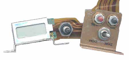
Each operating control, indicator and connector on the radio set is identified in the photos above and described in paragraph 3.4.
As a result of spurious signals generated in the frequency synthesizing process, receiver sensitivity may be slightly reduced on certain frequencies. The following table is a listing of these frequencies. Some minor variation, set to set, in the severity of this reduction canbe expected, however, only the frequencies so identified by an * the thetable have been found to occasionally degrade beyond service conditionlimits
46075 50675 61425 71675 81925 47075 54650 61450 76375 * 83925 * - 54675 64175 76400 * - - - 64200 76425 * - - - 64225 76450 * - - - 66550 76475 - - - 66575 76500 - - - 69850 76800 * - - - 69875 79350 - - - 69925 - - Because the VHF High Band has a 75% bandwidth (compared to the 293 % BW for VHF Low band) there are no spurs in High Band.
Figure 3-1 Controls, Indicators and Connectors -
| Name | Nomenclature | Index No. | Description |
| ANT connector | J4 | 1 | 1/4" X28 thread for the 20" helical wound antenna or, use an adapter for a 50 Ohm antenna. |
| AUDIO connector | J5 | 2 | Standard U-183/U style connector for use with external
handset, or frequency transfer cable (cloning device or frequency programmer) |
| SPKR/MIC | LS1 | 3 | Functions as a built-in speaker (receiver) and microphone
(transmit)when
external handset is not connected. When an external handset or headset is connected the internal speakerwill go into mute mode. |
| 3/8 selector switch | S7 | 4 | Selects either wide band (8 kHz deviation) or narrow band (3 kHz deviation)operation during radio set programming. After radio set is programmed,the switch has no effect. If a SVM is installed, radio set goes towide band automatically. |
| INC pushbutton switch | S9 | 5 | Pushbutton used during program mode to set value of each digit in display. |
| SET pushbutton switch | S8 | 6 | Used to initiate the program mode, step through digits in display and load new frequency information. |
| SQ DSBL pushbutton switch | S4 | 7 | Used to disable radio set squelch circuit (noise heard in
speaker)and display radio set operational mode. "LO8" means that a VHF low band module is installed and 3/8 is setto 8 kHz. |
| FREQ display | DS1 | 8 | Five digit Liquid Crystal Display (LCD) used to indicate the
selectedpreset
channel frequency in MHz. If a split frequency channel,
thedisplay
will show the Tx frequency while PTT is depressed and the Rx frequency
when in receive mode. To turn on the backlight depress the SET pushbutton. There is no backlight. When a high band module (130 to 174 MHz) is installed the leading "1"is NOT displayed (use the SQ DSBL switch to know which module is installed). Other indications are as follows: LO3 - When SQ DSBL is pressed, indicates radio set is configured for 30 - 88 MHz narrow band operation (3 kHz deviation) LO8 - When SQ DSBL is pressed, indicates radio set is configured for 30 - 88 MHz wide band operation (8 kHz deviation) HI3 - When SQ DSBL is pressed, indicates radio set is configured for 130 - 174 MHz narrow band operation (3 kHz deviation) HI8 - When SQ DSBL is pressed, indicates radio set is configured for 130 - 174 MHz wide band operation (8 kHz deviation) LoAD - In manual programming mode, indicates data previously displayed is now loaded in the selected preset channel memory location. FILL - Indicates that a cloning device or remote programmer is connected and the radio set is in FILL mode and either sending or receiving program data. LO 1 through LO 9 then LO A - indicates that channel frequency data is being sent. |
| ANT match rotary switch | S5 | 9 | Selects proper antenna matching network for the operating
frequencyselected
or bypasses the antenna matching networks to provide a direct50 Ohm
output
impedance. Warning tone sounds in speaker if match is
incorrect.
Corresponding frequencies for each switch positionare as follows:
A = 30 - 37 MHz |
| CHAN rotary switch | S3 | 10 | Selects one of 10 preset operating channels. In programming mode, selects channel to be loaded. |
| VOL/OFF control | S2 | 11 | Turns radio set on (clockwise) or off (full
counterclockwise). Adjusts level of sound heard from radio speaker or handset earpiece. |
| PUSH TO TALK pushbutton switch | S1 | 12 | Enables radio set to transmit when pressed in normal
operational mode. Selects transmit frequency when pressed just prior to and with SET in manual programming mode. Initiates output of all channel frequency data when pressed in FILLmode. |
| SVM Jack and jumper Plug | J1 & P1 | 13 | Provides interconnection between SVM and radio set. Jumper Plug allows radio to operate when SVM is not installed. |
| Battery snap connectors | 14 | Connects battery to radio set. Radio female connector is positive |
The threaded hole that the antenna mates with has a 1/4" x28 thread different from the PRC-68 and PRC-126, PRC-128 and PRC-136 that have a 5/16" X 24 thread.NOTE
Only the 20 inch helical wound antenna should be used on the PRC-68B for either VHF low or VHF high band operation.
Fair Radio sells the 20" long AT-20/PRC-68B antenna.
The PRC-68B uses external power when the OFF-VOL control is turned on.
The H-250 Handset can be connected to the AUDIO connector. This allows the RT-1547/PRC-126 to be carried in it's Carrying Bag attached to a standard pistol belt. It also makes it much easier to manually program split Tx and Rx frequencies into a channel.There is a flat on the handset connector. If this flat is positioned on and parallel with the PUSH TO TALK side of the radio it will mate with a small amount of rotation saving some time. This can be easily done by feel.
When the channel is changed the Antenna warning tone may sound. If this happens just rotate the ANT coupler switch until a position is found where the tone stops. If the new frequency is lower than the previous one rotate the ANT switch toward A, if the new frequency is higher, rotate toward E.
This procedure tells you how to load preset channel frequency information into the radio set memory.
a. Remove 7/8" round access cover by turning counterclockwise.
b. Set CHAN switch to the channel number to be reprogrammed.
c. Press SET button. Radio set is now in program mode. The display indicates the left-most digit of desired frequency.NOTEd. Press INC button until proper number is displayed.
In a hi-band (130-174 MHz) configured radio set, the "1" is assumed and is not displayed as the left-most digit of the display.
e. Press SET button. The next digit to the right is displayed.
f. Repeat steps d. and e. until all digits are set to the proper frequency.NOTEg. Set 3/8 switch for either narrow band (3) or wide band (8) operation.
The fifth digit of the frequency increments are in 2.5 kHz steps (nn.nn00, nn.nn25, nn.nn50, nn.nn75 kHz).
(Due to the display limitation of showing only 5 digits, an "8" must be displayed instead of a "75").
If the fifth digit is 2 or 8, the sixth digit (not displayed) will be 5.
If the fifth digit is 5 or 0 the. sixth digit will be 0.
This is an automatic and internal function of the radio set.
h. Press SET button. "LoAD" is displayed. Channel is now loaded.
i. Repeat steps b. through h. to reprogram other channels.
Apply a thin film of silicone grease (item 5, table 1-2) to the access
cover gasket and replace the round access cover.
The reason to do this is to use the RPC-68B with a repeater or retransmission system. A pair of PRC-68B radios may be interconnected to act as a repeater or retransmission system using frequency splits to avoid the problem of receiver desense.
This procedure tells you how to load preset transmit offset frequencies into the radio set memory. These frequencies are used during transmit for half duplex operation.
a. Perform steps a. through g. of paragraph 3.9 for the desired transmit offset frequency.
b. Press the PUSH TO TALK button and, while holding it down, press the SET button. "LOAD" is displayed. The transmit offset frequency for the selected channel is now loaded.NOTEc. Repeat steps a. and b. as necessary to program other transmit offset frequencies.
The radio set normally displays the receive frequency used during half-duplex operation. To display the transmit frequency, press the PUSH TO TALK button.
NOTE
The receiver sensitivity may be degraded if the transmit and receive frequencies are in different antenna matching bands (Ref. Table 3-1).
d. Apply a thin film of silicone grease (item 5, table 1-2) to the access cover gasket and replace the round access cover.Very Different Split Frequencies
If split frequencies that are very different are programmed, for example receive on 30.0 MHz and transmit on 79.99975 are programmed, the antenna beep tone will sound until you turn the ANT knob to E. The transmit frequency is what controls the ANT match function, not the receive frequency.This is a very good way to handle this case as it allows split repeater operation where the Tx and Rx frequencies are in different antenna matching bands and also different filter bands. The 30 to 88 MHz band is split into two bands 30 - 50.975 and 51 to 88 MHz with filters in both the transmit and receive signal paths. By using a Tx frequency in one band and Rx frequency in the other band the repeater desensing will be greatly reduced. The PRC-25 & PRC-77 retransmission systems require 50 feet of separation when a diplexer is not used. It may be possible that two PRC-68B radios could be used in repeater mode and be quite close together without a diplexer in VHF low band operation. The PRC68B repeater cable is only 6 feet long.
For VHF high band operation there is only a single band so it's questionable how much desensing reduction is available using only the antenna matching circuitry differences and a 6 foot separation.
This procedure explains how to load preset channel frequency information from a master radio set into a second radio set using the optional frequency transfer cable.a. Refer to paragraphs 3.9 and 3.10 as required and load the desired frequencies into the designated master radio set.
b. Turn the OFF/VOL control on both radio sets to OFF.
c. Remove handsets (if used) from both radio set AUDIO connectors and connect frequency transfer cable between the two AUDIO connectors.
d. Turn both radio sets on. Both radio displays will indicate FILL and both will have squelch defeated (receiver noise present in SPKR/LMIC).
e. Press the master radio PUSH TO TALK button to start the data transfer. (you will hear data in the slave radio SPKR as each channel is loaded.)
f. Frequency transfer is complete when both radios become squelched and the master radio set displays a frequency.
g. Turn the OFF/VOL control on both radio sets to OFF.
h. Remove frequency transfer cable and install handsets (if used).
i. Turn both radio sets on and check channel 6 to verify frequency transfer.
Two radio sets can be configured as a repeater (retransmission) station using the optional repeater cable.
Use the following procedures to set up the two radio sets in the repeater configuration.a. Turn both radio sets on. Ensure antennas are installed on both radio sets.
b. Set the designated receive radio set CHAN switch to the repeater input frequency.
This frequency must be the same as the field radio sets transmit offset frequency.
c. Set the receive radio set OFF/VOL control to midrange.
d. Set the designated transmit radio set CHAN switch to the repeater output frequency.
This frequency must be the same as the field radio sets' receive frequency.
e. Set the transmit radio set OFF/VOL control to minimum volume but not OFF.
(Since the retransmission cable is symmetrical, then retransmission is possible.)
f. Connect the repeater interface cable between the two radio set AUDIO connectors.
g. For maximum repeater station range, locate the repeater station at as high a point as possible, free from any physical obstructions.Desense
Desense occurs when a receiver has a strong signal coming into the radio that causes the AGC to set the receiver gain to it's minimum value even though the strong signal is not at the radios receive frequency. The further from the received frequency the less of a problem this is. If the strong signal is in the stop band of the receivers input filter then it is not a problem. Since some of the filters in the PRC-68 family of radios may be low pass it would be best to make the transmit frequency of the repeater much higher than the receive frequency. That would mean that the field radios that would use the repeater would have their transmit frequency lower than their receive frequency.For example setup the repeater with a Tx frequency of 89.9 MHz and Rx at 30.0 MHz. Now the repeater receiver will have very good rejection of the transmitter.
The field radios would be set for Rx on 89.9 and Tx on 30.0. The field radios do not have a desense problem because they are far from the repeater.This is a different phenomenon than Squelch Capture.
4.1 Modes of Operation
The radio can be in a number of different modes of operation. Thefunction of the controls and indicators changes depending on the mode ofoperation.
The Modes are:
- Normal Squelched Receive - radio is quiet and Battery saver is operating
- Normal Receive Audio - audio signals are being sent to the Speaker or handset(mode 3?)
- Transmit - a signal is being transmitted from the Microphone or handset
- Repeater Tx - when the repeater cable is attached and the volume controlon the transmit radio set is at minimum
- Manual Programming - Tx and Rx frequencies are being set into the radiochannels
- FILL - channel data is being uploaded or downloaded
- Secure Voice Mode - activated when the SVM module is installed and theradio is on.
The 3/8 programming switch may be there to narrow the bandwidth when only non secure voice is used to improve the s/n ratio by 6 dB.
In the PRC-126 this is done automatically by a filter at the input from the secure voice module (or the jumper in non secure mode).
The other reason for the 3/8 switch would be to allow for compatible communications with commercial hi band VHF equipment, but maybe one half of the ham 2 meter repeaters use a sub audible PL tone so the PRC-68B would not work with them because it only has a fixed 150 Hz PL tone.
The radio goes into 8 kHz bandwidth mode when in SVM mode no matter how the channel was programmed, this is needed to pass the digital data.- Repeater (Retransmission) Mode - The receiving radio outputs a singnal that activates the PTT on the transmit radio.
AUDIO J5 Functions
See Chapter 8 Experiments on the AUDIO J5 Pins and AudioConnectors & Cloning - Fill - Retransmission web page for more information.
- Grounding the pin-F causes the LCD to display "FILL"
- momentarily ground pin-C while pin-F is grounded causes the LCD to countLO 1 to LO 9 then LO A (hex character for 10).
- Pressing SQ DSBL will cause TTL data (TTL noise?) to appear on pin-F (needto check PRC-68B)
- The audio output on pin-B has a DC level near 0 with the squelch quietingthe radio and the DC level jumps to about +6 when the squelch opens usedfor speaker mute.
The MX-18290 does NOT cause the PRC-126to go into the FILL mode. (need to check PRC-68B)- See Experiments below for more on this.
TSEC/KYV-2A Secure Voice Module SVM
This is compatible with the VINSON comsec system used on a number of military radios, KY-57 and KY-58.
The 16 kb/sec digital data is compatible with MIL-STD-188-220 the Estelle data link protocol.
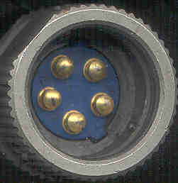
The 15 pin mating connector has the following terminals:
- 1 - Tx Cipher (12 kHz) to modulator (digital data interface?)
- 2 - Gnd
- 3 - Chopped B+ (generated by the battery saver circuitry)
- 4 - Rx audio (3 kHz) to speaker or handset
- 5 - Rx Cipher from receiver (12 kHz) (digital data interface?)
- 6 - Rx B+
- 7 - Squelch Disable
- 8 - Gnd
- 9 - 150 Hz Disable (150 Hz is disabled for secure coms)
- 10 - Gnd
- 11 - On/Off
- 12 - Tx B+
- 13 - Gnd
- 14 - Tx audio from microphone ( 3 kHz)
- 15 - Battery B+
In the jumper plug used when the SVM is not installed, (14 - Tx audio) is jumpered to (1 - Tx Cipher) and (5 - Rx Cipher) is jumpered to(4 - Rx audio). The Rx audio has a low pass filter to reduce thenoise that comes with non secure audio in a wide bandwidth. There are some more pins in the jumper plug that do not seem to be connected to anything?PCG-68 - Programmable Code Generator is used to load the . . .
CSD-68 fill gun (Code Source Device?) that in turn puts the key into the
TSEC/KYV-2A Secure Voice Module (SVM).The SVM attaches to the bottom of the radio with two screwsand the battery latches onto the bottom of the SVM using the same latches on the battery as are normally used for the radio.
Microcontroller
The brains of the radio is a microcontroller not a microprocessor. The LCD is a 7 segment type with no alphanumeric capability, only pseudo 7 segment letters therefore only 4 bits are required for each digit in the display. It is likley that the microcontroler uses 8 bit words sinse that would be approiate for the time frame when the radio was developed.
For repair advice you can contact Jim Karlow, KA8TUR He might do a repair, but it is a low priority.
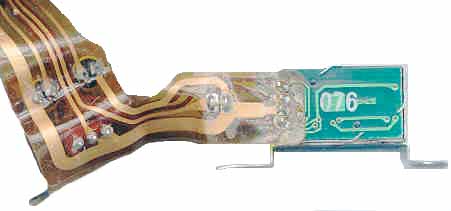
Disassembly
Flex removed from panel but still attached to the frame.In order to remove the flex circuit from the Panel (the top part that has all the controls), all the controls must first be disconnected.
Do NOT remove the antenna connector from the outside, there is a Phillips screw underneath to disconnect a wire.
The VOL and CHAN knobs are attached with two 0.050 hex screws per knob and a 3/8" nut.
The ANT knob (Grayhill 56SY2013-031N 8516 81073) is attached with 2 each 0.050 hex screws and a 5/16" nut. Be very careful not to break it like I did.
The SQ DSBL pushbutton is attached with a 7/32" nut.
The AUDIO connector is attached with a nut requiring a spanner wrench (or a screwdriver and small hammer).
The SPKR/MIC (2848 026 WP) is trapped in the panel and must be unsoldered prior to removing the flex circuit.
The FREQ display is held on by two Philips screws as are the SET, INC and 3/8 controls and PUSH TO TALK switch.
The SPKR/MIC can be left in the panel, or to remove it, take off the 4 screws that are normally visible and the Aluminum plate behind the grill then lift it out.The ANT switch is mounted on a board that contains the antenna matching circuitry that is mostly composed of inductors and capacitors. The flex circuit traces from this matching circuit go to the J3 connector. A white wire from this board goes to the ANT connector.
There is a diode on the flex circuit going from the AUDIO "E" pin to the OFF switch and another diode coming form the positive battery terminal also going to the same terminal of the OFF switch. These are the DC power routing diodes.
Cast into the panel are the legends:
Table 5-3 from MX-63-121 gives the CHAN programming information for testing the PRC-68B:
- S4 = ANT switch
- S5 = SQ DSBL
- DS1 = LCD Display
- J4 = Antenna connector
- S1 = CHAN switch
- S2 = OFF Volume switch
- J5 = AUDIO connector
These legends don't seem to match those above in the controls table.
CHAN Rx Tx BW VCO Volts ANT Band 1 30.025 =Rx 8 2 A 30 - 37 2 36.975 35.975 3 A 30 - 37 3 37.025 =Rx 8 4 B 37 - 46 4 45.975 44.975 3 7 B 37 - 46 5 46.025 =Rx 8 C 46 - 54 6 53.975 52.975 3 10 C 46 - 54 7 54.025 =Rx 8 2 D 54 - 66 8 65.975 64.975 3 D 54 - 66 9 70.025 =Rx 8 6 E 66 - 88 10 87.975 86.975 3 10 E 66 - 88 LCD
The LCD does not have a back light like on the PRC-126. It has 4 pins
SET INCR
SQ DSBL 8/3pin 1 = +5 V = J3-12
pin 2 = clock = J3-10
pin 3 = Gnd
pin 4 = data = J3-6
Figure 1-2 Major Components-The 3 5/8" high module housing for the PRC-68B is the same as the oneused on the PRC-126. The PRC-68 module housing is only 2 5/8" high.
Description NSN Figure Item FSCM Part No. RT Unit Fig 1-2 37695 Battery BB-388/U NiCad 1 Watt RF out Fig 1-2 Battery BA-1588/U Mercury 1 Watt RF out Batery BA-5588/U Lithium 1 Watt RF out Battery NiCad 16.0 VDC 2 Watt RF out 37695 54103-803 Battery NiCad 16.0 VDC 2 Watt RF out
with socket for TN-609 chargerBattery Case Fig 1-2 Lanyard Fig 1-2 Antenna 20" helical - 5985-01-212-3896 Fig 1-2 627095-1 Secure Voice Module KYV-2 or KYV-2A Synth/AF Module 815587-801 Low Band Module 815586-801
High Band Module TN-609/PRC-68B(V)
130 - 174 MHz
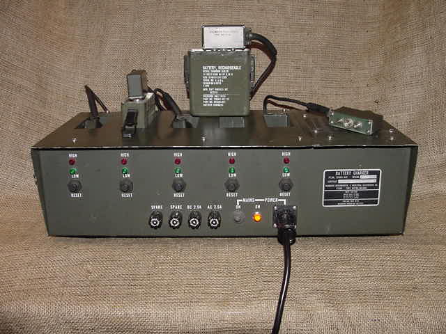
37695 816767-801 Handset H-138/U Handset H-189/U Handset H-250/U Ear Transducer EM-200 37695 588088-1 Frequency Transfer Cable 37695 568698-801 Repeater Cable 37695 568698-802 15 Watt Amplifier/Vehicular Adapter AM-7302/VRC-96 37695 707609-801 Battery Charger, Five Station 37695 706841-801 Battery Charger, Single Station 37695 565604-801 Long range portable field antenna - OE-254()/GRC Long range portable field antenna - RC-292
Antenna connector adapter 37695 914598-801 68BA Battery Adapter na na na na na 68AA Antenna Adapter na na na na na
MX-63-121 Technical Manual
Operation and Maintenance Instructions with Illustrated Parts Breakdown
Radio Set AN/PRC068B(V)1
Magnavox Part No. 707608-801
NSN 5820-01-179-7027
and
Radio Set AN/PRC-68B(V)2
Magnavox Part No. 707608-802
NSN 5820-01-248-2852
Contract No. M00027-84-C-0064 (This is a 1984 date)
MX-63-107, Ops Inst. ?
MX-63-121, Ops and Maint Inst. with IPB ?
Magnavox presales sheet for Ancillaries showing the cloning and repeater (retransmission) calbes with no bumps, just cables.
AN/PRC-68 Legacy by Alan D. Tasker, WA1NYR
These tests were done using a PRC-68B with the Synthesizer Module but WITHOUT the RF/IF module. The radio thinks it has a Low Band (33-88 MHz) RF/AF module.
Back to Brooke's Products for Sale, Audio Connectors & Cloning -Fill - Retransmission, Squad Radio, MilitaryInformation, Electronics, HomepageFILL cable
Using a 6 pin cable wired 1:1 connected between two PRC-68B radios (both with only the SynthAF module) the radios do NOT go into fill mode.
This is because Pin F is high on both radios.Adding a 22 K Ohm resistor between pin F and Pin A (ground) causes both radios to go into FILL mode, but although pressing PTT on one causes it to output the channel data, the other radio does not reprogram. In order to add the resistor an adapter was made with a male and female 6 pin audio connector and pins A and F were wired 1:1.
Data Protocol
Using the same technique as for the PRC-126 the data stream was analyzed. The PRC-68B is slightly different than the PRC-126.
There are 10 data frames with the same timing as on the PRC-126.
There is no empty frame, 5 are for Rx and 5 are for Tx.
The weighting is the same for the first 4 digits in the display (1,2,4,8) but the fifth frame has yet to be figured out.
The reason may be that the PRC-68B has provision for two different bandwidths, either 3 or 8 kHz.
The 10 frames correspond to radio channel numbers of 1, 2, 3, 5, 4,10, 9, 8, 6, 7 in that order, not in the order of the numbers shown inthe LCD.
This is different from the PRC-126.Hi Band Data Protocol
When J2 pin #8 is grounded on a radio that has the Synth/AF module, but no RF/IF module the radio thinks that it has a high band module installed. With J2 #8 open the radio thinks it has a low band module installed. This can be checked by pressing the SQ DSBL button and noting if the first two letters are LO or HI.By monitoring the AUDIO pin F data stream after shorting F to A and pressing PUSH TO TALK (both at the same time) the data output is the same as above for both high band and low band operation (remember that the leading "1" for 100 MHz is not displayed) with a single exception.
Just prior to the Start TTL high pulse for frame 6 on the Channel 10 (first data channel output) data set there is a high bit for 5 milliseconds.
This must be a bit that says that a high band module is installed.Resistance for FILL
One of my PRC-68B frames required about 330 Ohms to get FILL to come on, but another two radios only needed 10 K Ohms to get FILL, not shure why since I used the same Synth/AF module in two of them. Repeating the fill cable test above with these two radios, gave negative results, i.e.no frequency data was cloned.
[an error occurred while processing this directive] page created 19 Nov. 2000.