Audio Connectors
&
Cloning - Fill - Retransmission
© Brooke Clarke 2000 - 2004
U-229 Audio
Accessories - Separate web page
U-229 Pinout by
Function - seperate web page
Military Audio Accessories - Small Photos
Audio Connectors
Spade Lugs
Phone Tip Plugs
PL-55 1/4 Inch Phone Plug
U-77
MIL-C-55116 Connectors
U-228 & U229
U-182 & U-183 (U-229 with
6 Terminals)
Retransmission
Repeater
Remote Channel Programming
Cloning
Crypto Fill
Squelch Capture Jamming
Radio Wire Integration & Remote Control
Related
Glossary
Links
Audio Connectors
Spade Lugs
The Western Electric #D14842
Handset uses spade lugs.
Phone Tip Plugs
Were used on many early headphones.
Both
tips
are balanced audio connections, or one may be grounded.
PL-55 1/4 Inch Phone Plug
In W.W.II the audio connectors were the same as common civilian
connectors. For example the 1/4" phone plug was used.
Since the jack makes a 1/4" diameter hole into the radio sand,
water and other things that should not be in a radio found a way
in. The HS-32 uses this
connector.
The tip is the hot audio connection and the sleeve is
ground. The current U-229 family of connectors are sealed.
When a Stereo 1/4" phone plug is used the common assignment is:
- Sleeve - ground
- Ring - Right
- Tip - Left
The jack that accepts the PL-55 and other 1/4" phone plugs can be
obtained with contacts that are switched by the presence of the
sleeve. This can be used to mute a speaker when a headset is
plugged in. [I modified a B&W TV set by adding a
switching 1/4" jack so that when I plugged in the headphones the
internal speaker was turned off. It also needed a resistor
network so that the volume would be about the same in the
headphones as with the speaker, otherwise it was WAY to
LOUD.) This mechanical switching function is not present in
the MIL-C-55116 (U-229 family) connectors or the U-77 (10-pin)
connectors but can be added by sensing the resistance between
pin-A (gnd) and pin-B (headphone).
The identification of phone wires as Tip and Ring comes from
the 1/4 plug used on switchboards.
U-77
By the Korean conflict the audio connector was
standardized on a single U-77 10-pin connector as used on the PRC-6, PRC-47
and other radios. This connector is sealed on the radio thus
not allowing sand and other stuff to get into the radio. 10
pins makes it expensive both in terms of the connector proper as
well as the associated cable.
The H-33F/PT Handset that uses a
10 terminal U-161/U connector.
H-233 Handset, LS-166 Speaker, H-90
Handset , M-29B uses this connector.
- A - Receiver Audio
- B - Receiver Audio Ground
- C - Carbon Mike Input
- D - mike ground
- E - PTT then Mike
- F - isolated Push To Talk
- H - isolated PTT Ground
- J - Remote On-Off
- K- CW Key
- L - Speaker
MIL-C-55116 Connectors
Not only are these connectors water proof at the radio
connector (the radio can be submerged) they also have a water
tight contact area between the radio and the accessory.
This is done with an O-ring in the audio accessory connector
that mates with a smooth barrel on the radio connector.
The 5 and 6 pin version of this connector are all covered by
specification MIL-C-55116.
The U-228 and U-183 are typically panel mounted receptacles on
the radio and U-229 (5 pin) and U-183 (6 pin) are plugs mounted
on audio accessories.
DSCC - MIL-C-55116
specifications - Qualified
Parts
List
(QPL) for the 55116 Connectors -
Approved Vendors are:
General
Connector FSCM
25330 (609) 935-7370 - Newark
with on line ordering, pg N60 in Catalog 118
Nexus Inc.
FSCM
28986
(203) 327-7300
Power Connector FSCM
0CS66 (516) 563-7878
U-228 (chassis) & U-229 (handset)
The M-80C microphone, H-250 Handset has the 5 terminal U-229A/U
connector with the following pin definitions:
|
Pin
|
Audio Function
|
|
A
|
Ground, Negative Battery |
|
B
|
headphone audio |
|
C
|
PTT Key on hook = short, PTT off hook = open ckt |
|
D
|
Microphone audio |
|
E
|
Vehicle B+ on the PRC-68 & PRC-126,
Retransmission (switch to ground when receiver squelch
opens)
on PRC-25, -77, RT-246 |
The PRC-25, PRC-77,
VRC-12, PRC-74 radios use the U-228 audio connector.
TM 11-5965-280-15 (ETM 014514.pdf)
for the H-189/GR has some information on the U-229 connector.
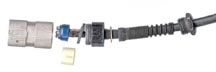 U-229
Connector opened to show the internal construction.
The white plastic sleeve has a slot so that it can be
removed/installed first/last. There are two
asymmetrical slots in the connector shell and two ridges
on the blue plastic terminal holder so that when the terminal
holder is installed in the connector shell the relative
rotational position will always be the same.
U-229
Connector opened to show the internal construction.
The white plastic sleeve has a slot so that it can be
removed/installed first/last. There are two
asymmetrical slots in the connector shell and two ridges
on the blue plastic terminal holder so that when the terminal
holder is installed in the connector shell the relative
rotational position will always be the same.
U-183 (chassis) & U-283 (handset)
(U-228 & U-229 with 6 Terminals)
U-183/U 5 terminals, panel mount NSN 5935-00-823-0667
This connector has 6 terminals, A through E are exactly the same
as on the U-229 and a sixth terminal is added in the center.
A radio with a 6 terminal U-182 audio connector can use all the
U-229 5 terminal audio accessories. Only when the function
of the sixth terminal is being used does the radio need a mating 6
terminal connector. AUDIO
6-Contact-Standard
(Conforms
to MIL-C-55116)
|
Pin
|
Audio Function
|
Possible Digital Function
|
|
A
|
Ground, Negative Battery |
Ground, Negative Battery, digital ground |
|
B
|
headphone audio |
audio +6 VDC when audio present
(external handset sense, Spkr mute)
WIth a Dc resistance <10 K Ohms PRC-126 or <3.3 K
Ohms PRC-68
the internal SPKR is muted |
|
C
|
PTT Key on hook = short, PTT off hook = open ckt |
data from RT-1439 |
|
D
|
Microphone audio |
data to RT-1439 |
|
E
|
Vehicle B+ on the PRC-68
& PRC-126,
Retransmission (switch to ground when receiver squelch
opens)
on PRC-25, PRC-77, RT-246 |
This is used as a power input for the radio.
The PRC-126 will run from a 10 - 18 Volt (12 volt nominal)
car supply. |
|
F
|
none
|
Used to put PRC-126 into FILL (digital) mode,
digital data output (PRC-126)
Pressing SQ DSBL causes digital data (TTL noise?) to
appear
|
The RT-1439 radio uses the audio connector for digital data
including TRANSEC variables, hopsets and lockout sets.
This is described in
TM 11-5820-890-30-5 (070228.pdf) in Chapter 2
"Receiver-Transmitter, Radio RT-1439/VRC. Maintenance
Instructions" and
Chapter 18 "Fill Device ECCM MX-10579/VRC and MX-18290/VRC Maintenance
Instructions".
See Figure 2-11 "Fill
Circuit Diagram" J3 is the 6 pin U-229 AUDio/FILL connector.
- A - n.c.
- B - n.c.
- C - Serial Data From Radio
- D - Serial Data To Radio
- E - Clock (1k to 4k), Fill Request (-6.75 V pulse)
- F - ?
The MX-18290 does NOT cause the PRC-126 to go into the fill mode.
The 6 pin connector that's in the PRC-126 and other radios is the
3012761-2 80063 25380.
Retransmission
Single Band Retransmission
Retransmission is like two repeaters that are cross
connected. In a retransmission setup either radio can act as
the receiver, whichever radio receives a signal first becomes the
receiving radio and keys the other to become the transmitting
radio. This mode allows the squad radios to operate in
simplex mode allowing them to talk directly to each other, yet
also talk to other radios through the retransmission system.
Note that in this system the squad radio is set for simplex
operation at either of the repeater frequencies, but can only
talk through the repeater to radios that are set for the other
frequency. For example a squad may have all their radios
set for 51.0 MHz so they can talk directly to each other and the
headquarters station may be set for 54.0 MHz so HQ can talk to
anyone in the squad, assuming a repeater with radios connected
with the MK-456 and the radios tuned
to 51 and 54 MHz. Also if a squad radio is out of contact
with the other squad radios it can try switching to the
retransmission frequency and talk to the rest of the squad.
For squad radios that can operate on split frequencies
(PRC-68B, PRC-126, etc.) the squad radio could be set to Tx on
51 and Rx on 54. Now the squad radios can NOT talk to each
other at close range, but only through the retransmission (or
repeater) system.
Cross Band Retransmission
This is one of the great strengths
of the retransmission system. Radios operating on different
frequency bands can be easily setup for retransmission, such as a
VRC-74 (PRC-77) and
GRC-213 (PRC-104) since both radio
systems have the common
VIC-1
connector. This way a hand held VHF squad radio like and of
the
PRC-68 family, can be used for 2
way HF communications.
Manpack Mk-456 Retransmission
The army has the MK-456
retransmission cable kit (TM 11-5995-202-15 (017891.pdf)) that
has a 50 foot long cable that interconnects the audio connectors
on two radios like the PRC-25 or PRC-77, RT-246 and others with the same
audio connector. The cable contains a lot of RF filtering
and the TM
11-5820-398-12 (018816.pdf) for the PRC-25 contains a spurious chart
showing the transmit and receive frequencies that will interfere
if used as a repeater pair. To use this kit the two
frequencies must also be at least 3 MHz apart. Both
repeater radios are in receive mode and the one that receives a
signal becomes the source for audio to the other (transmitting)
one.
* works with simplex radios like the PRC-68 PRC-25/77, VRC-12
that do not have split Tx-Rx capability.
Example: retrans setup 51 MHz input and 54 MHz output.
People who have radios that can talk and listen on 51, when in
range of a retransmission system, can talk to others who are on
54 simplex, like the SLO talk in staff.
If someone has half duplex capability they can set up for Tx on
51 and Rx on 54 and talk to others who have the same set
up. Others may set up for Tx on 54 and Rx on 51 and can
talk to each other, but not to the other group.
A problem with retrans is that if the repeater is busy?
If the CU-2194/URC Diplexer is
used both radios can be connected to a common antenna. And the
50 foot separation is no longer required.
On some radios there is a connector labeled RETRANSMISSION that
is used with other similar radios to make a simplex repeater.
The (U-183) retransmission cable used with the RT-1439 is cross wired as follows:
- B ->D
- D<-B
- E->C
- C<-E
- F--F (TTL Hi = Analog mode, TTL Low = Digital mode)
- A--A
FM
24-12 - Communications in a "Come-as-You-are" War
c. The planning range can be further extended with
retransmission operations.
(1) Retransmission, or retrans for
short, offers the commander a valuable alternative when
multichannel equipment is in short supply or absent. As with
NRI, retransmission is often not used to maximum advantage
because of lack of knowledge or lack of confidence in its
effectiveness. A shortage of multichannel equipment requires
better planning and use of all other communications assets;
retransmission is no exception.
(2) A primary application of
retransmission is the extension of a particular communications
link such as an FM command net or a fire direction net.
Another application might be a logistical link from brigade
trains to the DISCOM area in the absence of multichannel.
Traffic on this link would be for urgent requests for resupply
of critical items only such as ammunition or POL, or for a
contact team for the maintenance of critical items. Routine
traffic should be sent by other means.
(3) Retransmission should also be
used to support anticipated operations or planned moves of
important elements. For example, if a brigade CP is moving to
a certain location at 1600 hours, a retransmission station
could provide a communications link back to the DTOC.
Retransmission may also allow the brigade CP to locate in a
position that provides better physical security while still
maintaining its essential FM radio communications.
(4) Retransmission sites must be
carefully chosen to maximize retransmission distance while at
the same time minimizing enemy interception. Several alternate
sites should be chosen for each retransmission facility to
allow for periodic displacement.
VIC-1 Based Retransmission
Another way to achieve
retransmission is to use equipment that can be interfaced with
the Vehicle Inter Communications equipment (VIC). The
C-2299 Retransmission box can be used stand alone or with the
AM-1780 Amplifier to interconnect two radios that are on vehicle
mounts (although not necessarily in a vehicle, in my case they
will both be indoors.) to allow retransmission.
Radio Wire Integration Based Retransmission
By using a GSA-7 (old tube type
equipment) at both ends, two radios can be configured for
retransmission. The manual mentions this application.
In a similar manner the C-6709/G can be used for retransmission
by connecting them back to back with 2 pair of field wire.
Have not tried this but it should work.
Cautions
There are a number of possible
problems with retransmission.
Wrong R.F. frequencies
The back of most manuals for the
PRC-25 and PRC-77 have graphs showing those frequencies where
spurious responses will degrade the performance of
retransmission systems. These frequencies are to be
avoided.
De-Sense
When a powerful signal gets into
the R.F. front end of a receiver, even though it is outside
the receivers I.F. passband, it can cause the AGC to turn the
gain way down. When this happens the sensitivity of the
receiver is greatly degraded and it will no longer properly
receive signals that it otherwise could receive. To cure
this problem either the two antennas need to be separated by
say 50 feet for a pair of
PRC-77
radios, or more for more powerful radios or use a diplexer,
like the
CU-2194 with the two
transmit frequencies following the separation specs for the
diplexer.
RFI - EMI
Another path for the transmitted
R.F. is through the retransmission cabling. Even if the
antennas are properly separated, if the cable allows R.F. a
good path, then the De-Sense problem may still be
present. For this reason and also as part of good
design the retransmission cable contains chokes and bypass
capacitors on all lines.
Frequency Planning
Just like for a repeater, the
frequencies used need to be selected not only based on the
avoidance of problem frequencies, but also they need to be
compatible with the users radios.
Repeater
Standard Half Duplex
This is similar to Retransmission but works differently.
Repeaters are very common on the amateur radio VHF and UHF
frequencies as well as commercial and emergency services. It
takes 1/2 of the equipment to make a repeater than to make a
retransmission system.
A repeater has a radio acting solely as a receiver that feeds
another radio that is acting solely as a transmitter. They
are on different frequencies and may connect to a common antenna
if a diplexer is used to keep the transmitted signal out of the
receiver.
For the military there are two down sides of repeaters as
compared to retransmission. In both of these cases
retransmission continues to work without changing channels.
This is very important because how would someone know to switch
channels?
- If the repeater is taken out no one can communicate on the
repeater frequencies, but could just switch to another channel
IF THEY KNEW TO DO SO.
- If someone is in a spot where they can not hear or talk to
the repeater, but is within simplex range of their squad,
retransmission will work seamlessly, but the repeater fails.
Simplex
A simplex repeater consists of a
voice recorder that's put into record mode when a signal is
received and goes into play mode when the input signal stops or
when it has run out of memory. The Radio Shack
19-345 works this way. These are
very easy to use since only one transceiver and one antenna are
used. They are also great for drive testing since the test
can be done by one person. Typically used for emergency
coms and in sparsely populated areas.
They cut the available bandwidth in half, since the channel is
being used to record the message and then to play it back, a
very poor way to rag chew. Not a good thing to use in a
populated area where all available channels are being used.
Full Duplex
I don't have any experience with
these, but understand that you can get some hand held
transceivers that work both VHF and UHF. By using one band
for receive and the other for transmit, there is enough R.F.
isolation to prevent de-sense. This would allow a
telephone like conversation where you can interrupt and
talk over the other person.
Remote Channel Programming
Either a stand alone keypad can be used to program a
radios channels or a programming cable and a computer. This
is done using the 6-pin U-229 audio connector.
Racal PRC-139 MX-11532/U
Frequency Fill Device, MA
6941 PC programming cable
Cloning
The idea of cloning is to allow a number of radios to
all be programmed with the same channel frequency
assignments. This is a tedious process when done by hand.
There are a couple of ways of cloning the frequency
assignments.
- A cloning cable will allow the frequency assignments to be
moved from a "master" radio directly to a "slave" radio.
- A frequency transfer cable will allow the frequency
assignments to be moved to/from a computer.
Racal PRC-139 - Cloning
Cable -this is really not a cable with 2 connectors, it is
a cloning device that has only one connector.
Magnavox pre sales sheet for Ancillaries
showing the cloning and repeater (retransmission) cables with no
bumps, just cables.
Crypto Key Fill
The key for a TSEC/KYV-2()
Secure Voice Module has its key loaded filled using an audio
connector on the SVM, not the radio.
The MX-10579/VRC and/or MX-18290/VRC
SINCGARS Fill Device may have a clue and will be analyzed
shortly.
TM 11-5820-890-30-5 Chapter 18 has some operation
information on the Fill Device.
eBay Photo - on the
rotary switch:
- "A" means fill All channels
- "1 through 13 are individual channel numbers
- T1 through T3 = ?
The button in the center is to INITIATE a transfer from the fill
device.
The cable used with the Fill Device is a 6 wire cable wired 1 -
1.
Racal PRC-139 - Crypto
Fill Cable - this looks just like the cloning device
The Racal PRC-139 and PRC-6725 can
also be connected to a computer with the MA6941 interface cable.
Squelch Capture Jamming(Wiki: Capture
Effect)
On those radios that must see 150 Hz to open the squelch
(PRC-25, PRC-77,
AN/VRC-xx) there is the possibility
that an enemy can transmit on the frequency of the radio but
with no 150 tone. This will lock up the receiver and not
allow normal communications to get through.
To test for Squelch Capture, press the SQ DSBL button on the
radio. You should hear static. If there is no static
you are being jammed.
The SINCGARS radios do send the 150 Hz tone when not
hopping. But I doubt if they need to see the 150 Hz tone
when hopping as there would be no point. Note that a
hopping radio is a very good countermeasure to squelch capture
jamming. For example a 100 Watt single channel jammer can
put a strong signal on a receiver like the PRC-77 that's tuned
to one channel. But a 100 Watt wide band jammer covering
30 to 80 MHz (2,000 channels) only puts 0.05 watts into each
channel.
AM radios can hear two stations on the same channel when the
difference in signal levels varies over a large range.
This is why aircraft radios still use AM. An FM radio can
only hear two stations at the same time if their signals are
very close to the same power level. Once one signal is a
few dB stronger the radio "captures" the strong signal and
eliminates the weak one. FM quieting is a way of measuring
how quickly this happens.
3091735
Frequency modulation interfering signal selecting system, Richard
K Moore, General
Electronic Laboratories, 1963-05-28, - a jamming
countermeasure
Radio Wire Integration & Remote Control
RWI
Also known as Radio Net Interface
(RNI). The Plain Old
Telephone
System uses a 20 Hz ringing signal that is too low in frequency to
be sent over a voice radio channel (300 - 3,000 Hz). So to
interconnect phone equipment with radios a tone generator is
needed to convert the ring signal to 1,600 Hz that will pass
through the radio channel. And at the other end that tone
needs to be notched out so it does not show up in the speech audio
yet it needs to be detected and used to turn on a ring
generator. The GRA-7 is used for this purpose. It can
be used in three system configurations:
- Between two telephones to provide a radio link instead of a
wire link (2 telephones & two radios)
- Between one telephone and a radio by means of another radio
(1 telephone & 2 radios)
- Between two radios for retransmission (the retransmission
part has 2 radios and no telephones)
The German
Funkanpaßgerät WT-FM-E1 AP01
is one of this class of devices.
The
GRA-39 does NOT do this by itself,
it requires an operator. The GRA-39 does not send the 1,600
Hz tone over the radio channel that's required for radio control
of the ring signal. The old tube GRA-7 does this without any
operators.
The C-6709/G replaces the GRA-7 but only when connected to 4-wire
switchboards, not
2-wire
phone
lines or switchboards like the
SB-22.
But
it
could be used for a
retransmission system by
connecting two of them back to back with 2 pair of field wire
between each. Should work but not tested. But it can
not be used for connection to a single phone line, like the GSA-7.
Remote Radio Control
For short distances you can just use an extension cord on the
handset. But this requires shielding to keep RF out of the
phone circuit and only works with good connections, not for miles
of distance using field wire.
To avoid using the field wire pair to carry DC, a 3,900 Hz tone is
sent from the GRA-39 Remote unit to
signal PTT closure. At the Local unit the 3,900 Hz signal is
separated from the voice signal and used to key the PTT on the
radio. The voice signal is highly amplified prior to being
sent over the wire pair then attenuated prior to being applied to
the radio. This maintains a good signal to noise ratio for
the voice signal. In this system there are no signaling
tones transmitted by the radio, only voice. There's also RFI
filtering to keep the transmitted RF out of the phone circuitry.
Glossary
Simplex
Refers
to
transmission in only one direction. Simplex refers to
one-way communications where one
party
is
the transmitter and the other is the receiver. Note the
difference between simplex and half-duplex.
Half-duplex
Refers
to
two-way communications where only one party can transmit at a
time. An example of half-duplex
communications
is
almost any two way radio, you can receive from stations but can't
transmit at the same time.
Full-duplex
Refers
to
the transmission of data in two directions simultaneously. For
example, a telephone is a
full-duplex
device
because both parties can talk at once. In contrast, a
walkie-talkie is a half-duplex device
because
only
one party can transmit at a time.
Related
Beltone 12D Audiometer
Teledyne Avionics TA-3D Acoustic Impedance
Meter - allows applying positive or negative pressure and
then measuring the impedance of the ear.
TS-2839/GY German Audio Test Set
General Radio Audio Testing equipment
Freed-Eismann Radio Speaker FE-50
- efficient horn type loudspeaker
FreqStd Frequency Standard, Audio
HP204 HP 204B Audio Oscillator from HP
3350 Carrier Test Set (AN/USM-181 Telephone Test Set
HP241A HP 241A Audio Oscillator w/Radio
Buttons
HP33120 HP 33120 Function Generator
-both audio and sub audio frequencies and various harmonic
contents because of waveform
MAA Military Audio Accessories
M1024 Magnacord 1024 Reel to Reel Tape
Recorder
SDAR Signal Design, Inc. 65630 Audio Recorder
RD-609/TSQ-164 Communications Recorder
Surround Sound 7.1: Sub woofer, Setup,
TS585 TS-585 Audio Level Meter
U229AA U-229 Audio Accessories
U229PO U-229 Pin Out by Function
U229Y "Y" Cable, U-229/U
Voice of the Theater speakers
- efficient exponential horn + 15" woofer with voice coils in same
vertical plane to avoid phasing problems at crossover frequency
Links
Electro-Voice
- their web page is under heavy construction (8 Nov 2000)
Military
Radio Accessories Specification Page - microphones,
handsets, and 5 & 6 pin AUDIO connectors -
Richard
Lacroix's Military Communications Home Page
Sonetronics - maker of
H-350/U and other mil components with a web page with specs for
about all mil mics, head and hand sets & speakers, etc.
Planning
SINCGARS
RETRANS
Team operations - SINCGARS
FM 24-18 Retransmission
chapter -
Tacticom - Audio
Component Products - Audio -
Tactical Command
Industries, Inc. - Headsets
Brooke's Home, Military
Information, Electronics Page
[an error occurred while processing this directive] page created October
17, 2000.
 U-229
Connector opened to show the internal construction.
The white plastic sleeve has a slot so that it can be
removed/installed first/last. There are two
asymmetrical slots in the connector shell and two ridges
on the blue plastic terminal holder so that when the terminal
holder is installed in the connector shell the relative
rotational position will always be the same.
U-229
Connector opened to show the internal construction.
The white plastic sleeve has a slot so that it can be
removed/installed first/last. There are two
asymmetrical slots in the connector shell and two ridges
on the blue plastic terminal holder so that when the terminal
holder is installed in the connector shell the relative
rotational position will always be the same. 