RF Module has two sockets for Tx crystal units (SO1 and SO2)
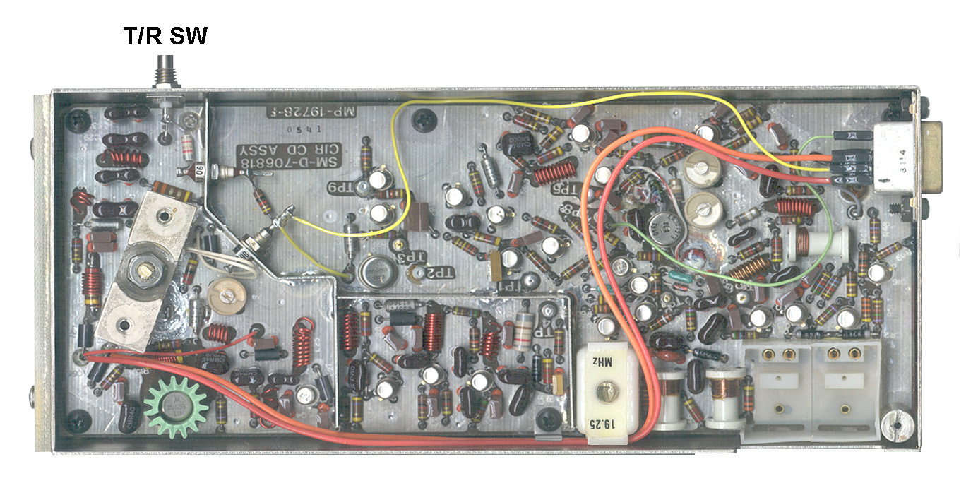
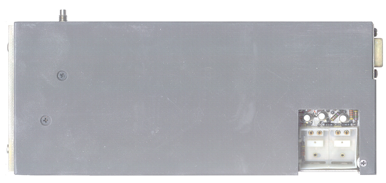
Inside of RF module
RF Module has two sockets for Tx crystal units (SO1 and SO2)
Inside of RF module
This is an example of Sound Ranging (Wiki) aka Acoustic Location (Wiki) aka Artillery Sound Ranging (Wiki) which has been around since W.W.I.
TM 11-2552A "Sound Locating Set GR-6-A" June 1951 - components: BC-1323 Processor (my name) includes three audio channels and a wire recorder used to measure the time delays. This is done by manually scanning the wire using a CRT. Requires an external 6 V battery box and can be linked to a SCR-300 radio for an unknown to me purpose, probably to report the results for counter fire.
The AN/TNS-10 system was a wire line system for determining the location of explosions, like from artillery firing or impacting. A number of special microphones, typically installed in shallow holes in the ground, are amplified and low pass filtered. A square array of 9 microphones fed an electrostatic pen recorder. Knowing the microphone positions and the speed of sound the bearing (and maybe distance) to the loud noise could be calculated.
Since the chart recorder has a high speed paper feed it's important to have good control of starting and stopping the system to conserve the paper. The system specifications have all kinds of requirements to be sure paper is not wasted. The output charts would need to be interpreted by a human.
The GRA-114 replaces all the microphone wiring with radios, saving a lot of wire.
My guess is that the TNS-10 and GRA-114 have been replaced with the TPQ-36 mortar location radar and the TPQ-37 artillery location radar. These TPQ-xx systems use radar to track the ballistic projectile and compute the source location before the first round impacts. These radars were made by Hughes in either El Segundo or Torrance California.
The KY-671 "Decoder-Indicator" that works with the PRC-25 may be related to the GRA-114 sound locating system.
Acoustic location of gun fire based on time of arrival is now being used in major cities. For more accoustic gun shot location see my Sensors web page (Wiki).
Artillery Sound Ranging - using British tube equipment.
The RT-1183/GRA-114 Transmitter Receiver, Radio Data Link, Sound Ranging is a similar but larger unit that probably uses the same Tx and Tx crystal units.
Part 3 of FM 6-15 is on Weather and it's application to Sound Ranging which includes a Principles of Sound Ranging chapter.
The modern way to locate artillery, mortar, rocket &Etc. fire is by use of RADAR. The RADAR is constantly scanning the sky and in a very short time gets a number of hits from an incoming projectile. It then computes the location of the equipment that launched/fired it and passes this digitally onto a counter fire weapon system which in turn fires a few rounds at that location. The counter fire projectiles will be in the air before the incoming round hits the ground. I was a couple of these systems first hand at Hughes Fullerton in Southern California. The TPQ-36 (Wiki: mortar) and TPQ-37 (Wiki: artillery) radars.
From the training course:"The Radio Data Link, Sound Ranging AN/GRA-114, hereafter referred to as AN/GRA-114, is a digitized special purpose communications system capable of transmitting voice when desired and analog representations of signals derived from weapons firings for the purpose of locating these weapons. A complete network consists of two sound observer (SO) stations which initiate system operation, eight microphone position (MP) stations (two spares) for detecting and transmitting signal information, and one command post (CP) station which receives, decodes and initiates the action required."
The GRA-114 is a Radio Data Link, Sound Ranging. Parts of the GRA-114 are:
- Command Post Receiver Transmitter RT-1183/GRA-114 (CPRT) and Antenna AS-4030/GRA-114
- Microphone Position Receiver Transmitter RT-1184/GRA-114 (MP) and Antenna AS-4031/GRA-114
- Sound Observer Receiver Transmitter RT-1185/GRA-114 (SO), Control Receiver Transmitter C-9887 & Antenna AS-4032/GRA-114
The RT-1185 is used in conjunction with RT-1183 and RT-1184 and is intended to provide a system control and a voice and data transmission facility as part of Radio Data Link Sound Ranging AN/GRA-114.
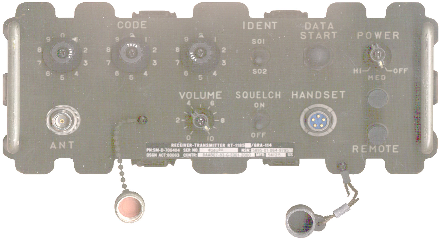
Markings
The label reads:
Receiver-Transmitter RT-1185/GRA-114
PN: SM-D-706404 Ser No 01010A NSN 5895-01-064-9795
DSGN ACT: 80063 Contr: DAAB07-83-G-E001-2000 Mfr: 54125 USNote that the GRM-114 is an general purpose communications test set made by IFR. This is a GRA-114CAGE code 54125 belongs to:
FERRANTI INTL SIMULATION AND TAINING /US/ INC 1995 some to GEC Marconi, but even they went to Mexico.
Status: H - Obsolete Record
Address: 801 S 18TH ST
City: COLUMBIA
ZIP: 17512
State: PA
CAO-ADP: S3912A - SC1010
Voice Phone Number: 717-285-7151 (only old legal and corp office, nothing technical)
Date CAGE Code Established: 8/19/1974
Last Updated: 7/25/1995Power Source
There is only provision for battery power using the +15 Volt tap on a BA-4386, BA-5598, or my 257475BA Battery Adapter. The battery box is the standard CY-2562/PRC-25 used on the PRC-25, PRC-77 and many other equipments. The boards run directly from the +15 Volt battery just with dropping resistor and cap filters on the boards. The CMOS ICs are rated for 15 volts.Controls
The top row (Tx functions?) has: three 10 position CODE switches (have diodes mounted for 8,4,2,1 binary weighting., IDENT of SO1 or SO2, a START DATA push button and the POWER switch has three positions: OFF, MED and HI.The bottom row (Rx functions?) has type-N antenna connector, VOLUME control, SQUELCH ON/OFF switch, 5 pin HANDSET connector and a pair of wire terminals marked REMOTE.
Component Parts
Front Panel & Chassis SM-D-706596
No active components other than the diodes on the CODE switches.Tx Module SM-D-706622
There are two sockets that hold the transmitter crystal units. The appearance of these 2 sockets matches the socket on the TS-3630/GRA-114.DB-9 connector has only 6 wires:
1 = Blue
2 = nc
3 = White/Red -> Power switch (Hi only) <-> Fuse <-> Battery +15
4 = White/Purple - tbd
5 = White -> POWER switch (MED and HI) <-> Fuse <-> Battery +15
6 = nc
7 = Black = Gnd
8 = White/Black - tbd
9 = ncCrystal Unit Frequencies
From Crystal Test Set TM 11-5895-1097-40
The top number is the marked frequency on either a Tx or Rx module, there is a Tx module and an Rx module with the same frequency marking.
The lower numbers are the actual Tx/Rx frequency of the module.
Tx Crystal Units
The Tx crystal units probably look like small metal box 0.9" x 0.6" x 0.4" high. 2 pins on the bottom about 0.16" apart.
These are just overtone crystals.
The actual Tx frequency times 2 plus 19.25 MHz is the marked frequency.
Rx Crystal Units
There are 3 SMB connectors. The input connector takes in the marked frequency and an LO and RF signal are output such that the difference is 18.1 MHz.
P3 (J4) in the input for the marked channel frequency.
P1 (J5) is fed +6.2 volts DC and is one of the outputs.
P2 (J6) is fed +12 volts DC and is one of the outputs.
P1 and P2 are close toghther and P3 (J4) is seperated by about twice the P1-P2 distance.
The actual Rx frequency plus 18.1 MHz is the marked frequency.
Marked Freq
actual Tx/Rx freq
Note that the Rx and Tx frequencies are more than about 1 MHz apart when they are in the same band or the Tx frequency is about 2 times the Rx frequency if they are in different bands. This way a single 1/4 ground plane antenna will work well for both Rx and Tx.
82.77
63.70/64.67138.10
59.425/120.0140.60
60.674/122.5143.10
61.925/125.0149.50
65.125/131.482.95
82.95/64.85138.20
59.475/120.1
140.70
60.725/122.6143.20
61.975/125.1150.20
65.475/132.1138.40
59.575/120.3140.80
60.775122.7143.30
62.025/125.2150.80
65.775/132.7138.50
59.625/120.4140.90
60.825/122.8143.40
62.075/125.3138.60
59.675/120.5141.00
60.875/122.9
143.50
62.125/125.4138.70
59.725/120.6141.10
60.925/123.0143.60
62.175/125.5138.80
59.775120.7141.20
60.975/123.1143.70
62.225/125.6138.90
59.825120.8141.30
61.025/123.2
143.80
62.225125.7139.00
59.875/120.9141.40
61.075/123.3143.90
62.275/125.8
141.50
61.125/123.4144.00
62.375/125.9
141.60
61.175/123.5
The actual operating frequencies seem to be within US TV channels 2 and 3. They are also within the tuning range of VHF low band Squad Radios.
Function Module SM-D-706623
Marked SM-D-706623 Ckt OD ASSY, SO FCTN MP-19730-D. Seems to be all analog circuitry with transistors and op amps.Encode Module SM-D-706624
Has 9 ICs either 14 or 16 pin, most likely CMOS type. A metal box marked "Y1" with two leads, probably a crystal, but with no markings on the box. L2 is a pot core inductor probably in the mH range that's near 5 transistors.Y1 is connected to a Motorola 14 pin IC marked JM38510/05202BCA (also made by Harris, National, RCA and TI). Some data at the National Museum of American History, Series 10 Integrated Circuit Engineering Collection GOVERNMENT TASC box # 17. The TI part was equivalent to the CD4001 CMOS Quad 2-Input NOR Gate.
T/R Switch Module SM-D-706635
Has 3 coax connectors: to Tx module, to Type-N antenna connector on the front panel and to a connector near the back of the Rx module. The two diodes are biased through J3 which goes to the Tx module.Receiver Crystal Module
A missing module that would have three SMB Jacks: two attach to the receiver module and one to attach to the connector routed to the T/R Switch. Most likely 3/4" x 3/4" x 5 " long. Probably supplies the RF and LO signals to the Rx module. Although the transmitter can transmit on one of two frequencies it's not clear what the SO1 - SO2 switch does in receive mode if anything.
Another possible function of this module is to act as a duplexer allowing voice coms on one frequency and data signals on a separate frequency.
Rx Module SM-D-706651
One transistor crystal oscillator in center of board. All analog circuitry, transistors and a CA3028 amplifier. DB-9(m) connector has pins 4, 8 and 9 as grounds. Total of 4 wires on DB-9 connector:
1 = White - tbd
2 = Orange - tbd
3 = Red -> POWER switch (MED and HI) <-> Fuse <-> Battery +15
4 = Black = Gnd
5, 6, 7, 8, 9 = nc
TM 11-5895-1095-12
TS-3630/GRA-114
TM 11-5895-1097-12 Covers the crystal unit test set.
the test set uses the SG-1112 to supply the received frequency test signal.
TM-11-4940-479-23P is for the SG-1112 which is the HP8640 combined counter & signal generator.
TS-3566/GRA-114
Code generation test set. SO1 is a START command and opens the line, SO2 is an End Of Word command and closes the line.
The description of how this test set works should be very similar to how the RT-1185 works.
Part of the test set is a 19.25 MHz output that's amplified and fed to the RT under test.
TM 11-5895-1096-40 * -40P
GB124805A (eSpaceNet) Improvements in Sound Transmission by Light Rays Actuating Photoelectric Cells, William Henry Bragg (Wiki), Alexander Oliver Rankine (Wiki), App: 1916-04-11, W.W. I, Pub: 1919-04-10, -
1351356 Sound-detecting device, Tucker William Sansome, App: 1919-01-06, Pub: 1920-08-31, - Low Freq Mike for gun location.
"The ordinary type of microphone is more sensitive with regard to sound waves produced by the shell traveling through the air than with regard to those of the actual discharge of the gun and consequently the position of the gun as obtained by means of such a microphone is not accurate and has to be corrected by calculation." ... "According to the present invention use is made of an electrically heated thin conductor in combination with a sound box and with means for producing a small blast of air past said conductor into the sound box by the effect of the sound or gun wave which it is desired to detect, measure, or record, such detection, measurement, or record being obtained by the variation in the resistance of said electrically heated conductor produced by the cooling effect of the blast upon the conductor." i.e. a low frequency mike that does not hear the supersonic crack of the projectile, but rather the boom from the gun.
No vacuum tubes, just galvanometers and speakers.
1753346 Sound-ranging system, George R Lum, Western Electric Co, Filed: Jun 19, 1923, Pub: Apr 8, 1930, 367/123, 200/14, 200/1.00A - find bearing to ship from it's sound (before RADAR).
2370176 Means for and method of measuring time intervals, Kornei Otto, Brush Development Co, App: 1942-06-22, Pub: 1945-02-27, -
2395127 Time-measuring instrument, Kornei Otto, Brush Development Co, 1946-02-19, - "... a steel disk rotated by a synchronous motor. Magnetic transducer means (which may be magnetic heads which combine the functions of recording and reproducing or separate magnetic recording and reproducing heads) are associated with the disk and a source of recording current is connected to the recording means," not clear what application.
2500643Condenser transducer independent of ambient atmospheric conditions, Munson Wilden A, Wente Edward C, Bell Telephone Labs, Dec 7, 1946, 381/174, 381/337, 381/191 -
5586086 Method and a system for locating a firearm on the basis of acoustic detection, Alfred Permuy, Pierre-Henri Vimort, Metravib FR, 1996-12-17, - 5 citations, cited by 32
US Counterbattery Methods That Made German Artillery Fire Once And Run, 36:53 -
Note William Henry Bragg (Wiki) is the father of William Lawrence Bragg (Wiki) and they both worked on sound ranging and both won the 1915 Nobel prize for X-ray crystallography.
Lawrence Bragg's role in the development of sound-ranging in World War I - William Lawrence Bragg (Wiki)Back to Brooke's Products for Sale, Military Information, PRC-68 Family of Squad Radios, U229 Audio Accessories, Audio Connectors, Electronics, Home page
Technology for Artillery Location, 1914-197,
Wiki: Sound Ranging, Gun laying, Prism paralleloscope, Mortar, Artillery
page created 5 March 2003.
