Much of the following operational and engineering information is from analyzing how the radio works and does not appear in any of the manuals.
1.1 Equipment Description
1.1.1 Purpose of Equipment
The AN/PRC-126 is a short range, handheld tactical radio for use primarily at the squad/platoon level. AN/PRC-126 is a lightweight, militarized transceiver providing two-way, voice-communications. The radio covers the frequency range of 30-87.975 megahertz. Its nominal range for reliable communications over rolling, slightly wooded terrain is 3,000 meters. The radio is capable of interoperating with the AN/VRC-12, AN/PRC-77, and SINCGARS families of radios in the fixed frequency mode. AN/PRC-126 enables small unit leaders to adequately control the activities of subordinate elements in carrying out the unit's mission. AN/PRC-126 is required for the Infantry, Rangers and Special Forces.The receiver transmiter is the RT-1547/PRC-126.
1.1.2 Characteristics, Capabilities and Features.
The physical and electrical characteristics of the radio set are given in 1.3 Table of Specifications.
Special capabilities and features of the radio set are as follows:a. Preset Frequency Channel Capability - The radio set is able to be externally programmed with - ten (10) preset f requency channels anywhere in the frequency range.
b. Warning Tones - The radio set generates two separate warning tones; one indicates the battery is nearing its end of life and the other indicates a mismatch of the antenna and the operating frequency.
C. Antenna Matching Switch - This thumbwheel switch selects the proper antenna matching network for the selected operating frequency. The antenna warning tone is enabled if the switch position is incorrect. In addition, the "50" position of the switch bypasses the antenna matching networks and provides a direct 50 ohm output for test use or any 50 Ohm external antenna,
d. Liquid Crystal Display - A lighted five-digit 7-segment display to indicate frequency, operational mode, and programming information. Early radios had a dark green NVG filter on top of the LCD which made it very hard to read in daylight. In later radios the dark green filter was placed between the back light and the LCD. There are some early radios that have had the green filter removed and replaced with a clear cover. These will have very bright back lights. For more on the LCDs see the 816173 Frame/Panel page.
e. COMSEC Operation - Provides 16 kb VINSON compatible secure voice operation by simple attachment of the KYV-2A NSA approved COMSEC device between the radio set and battery.The prior sentence is taken from the radio manuals, but the comments (see Links below) indicate that the radio is NOT capable of secure operation. This may be because of some problem with the KYV-2A or maybe just some other reason like the KYV-2A modules were not available in the needed quantity. The PRC-126 does not frequency hop like the SINGARS and other modern military radios.
When the battery voltage goes down to 10 volts the speaker will sound a low battery warning. Also if the channel or antenna tuning rotary switches are misadjusted the antenna tuning warning tone will sound. These may be heard by an enemy that is near by.
1.2 Photos
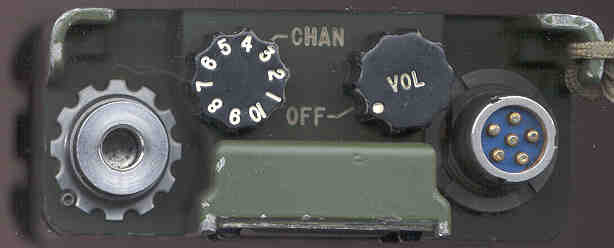
- Top Photo - Antenna conector on the left, CHAN switch, OFF-VOL control and AUDIO connector
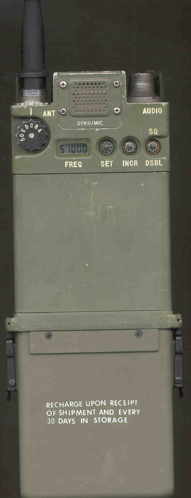
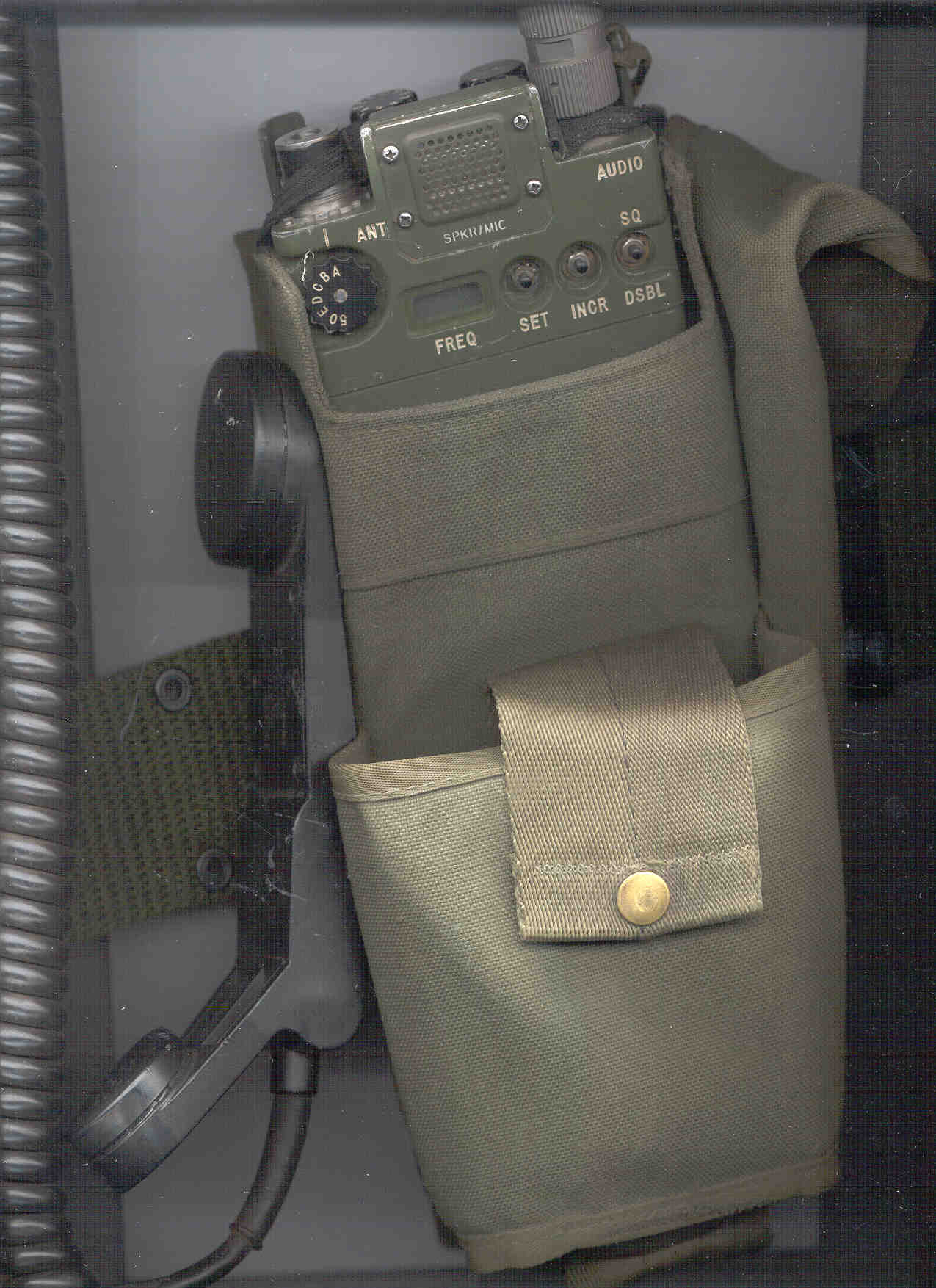
- Front Photo - ANT coupler rotary switch, SPeaKeR/MICrophone, 5 Digit Frequency Display, SET, INCRement and SQuelch DISable push buttons, and NiCad battery installed.
- Front Photo with Night Vision window on LCD, module housing and modules removed.
- Back Photo - PUSH TO TALK (PTT) swithch and NiCad battery with it's label
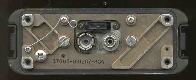
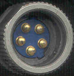
- Bottom RT-1547 Photo - Showing the J1 Secure Voice Module jumper installed on J1, the two battery terminals (Module housing is installed)
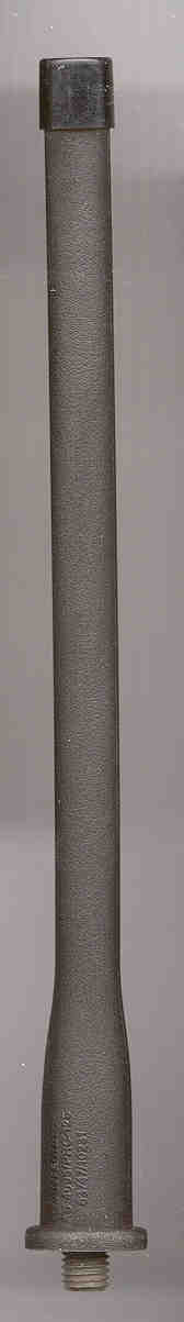
- AS-4094/PRC-126 7" rubber ducky antenna
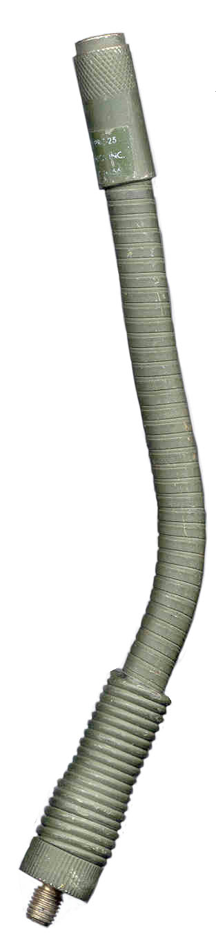
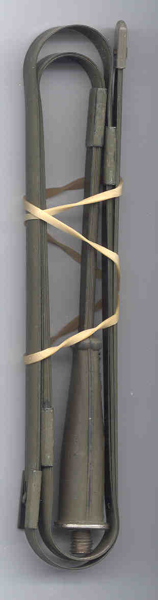
- AS-3575 a two part long antenna. The base is a goose neck that's 8.5" long and the 36" long measuring tape antenna
- H-250 Handset
- BA-5588/U Lithium Sulfur Dioxide primary battery used in the Battery Housing - remove the 1.25" x 1.25" x 3.5" rubber spacer
1.3 Table of Specifications
General Specifications
Frequency Range 30.000 MHz - 87.975 MHz Available Channels 2320 in 25 kHz increments Minimum Channel Spacing 25 kHz (12.5 kHz using computer loading) Preset Channels 10 can have seperate receive and transmitt frequency Modulation Frequency Modulation (FM) Operating Temperature Range -40 deg F to +131 deg F (-40 C to +55 C) Moisture Resistence Watertight to a depth of three feet Weight (battery, antenna included) 50 oz (1.42 kg) Size 9.97" (253.2 mm) x 3.78" (96.0 mm) x 1.52" (38.6 mm) Low Battery Tone Four 400 Hz beeps at six second intervals when Vbatt < 10 V Antenna Mismatch Tone 1000 Hz tone at one second intervals when selected frequency and ANT match switch position do not agree and the transmitter is disabled. Communications range - long antenna & goose neck 1.86 miles (3000 meters) Communications range - short (rubber duck) antenna 0.31 miles (500 meters) Typical power consumption 41 mA when in receive mode with the radio quiet
(0.8 AH for NiCad batt / .04 = 20 hours of Rx only time)76 mA when VOL is set at max and radio driving internal speaker (10 hrs of listen only time) 350 mA when transmitting (2 hrs of Tx only time) Transmitter Specifications
Power Output 1 Watt Frequency Control Built-in Synthesizer Frequency Stability +/- 25 ppm at 88 MHz Spurious and harmonics radiation 50 dB below RF carrier level (second harmonic 40 dB) Modulation Deviation 8 kHz, limited at 10 kHz
(this is about twice commercial practice)Squelch Tone 148 - 152 Hz, 2.5 to 3.5 kHz deviation Receiver Specifications
Adjacent Channel Rejection -60 dB Image Rejection -40 dB Sensitivity 0.3 microvolts for 10 dB SINAD Squelch sensitivity 0.3 microvolts Selectivity, 6 dB down bandwidth greater than +/- 13 kHz , 60 dB down bandwidth less than +/- 50 kHz Response to Spurious Signals -60 dB Audio Output less than 10 % distortion at 100 milliwatts
SINAD = (Signal + Noise + Distortion) / (Noise + Distortion) Squelch although 150 Hz is sent during transmission
the receive squelch operates based on signal not 150 Hz tone.18 May 2002 - When measured, one of my PRC-126 radios shows a fairly flat frequency response on receive from 100 Hz to around 8 kHz. This is much different than the PRC-25 that shows a peaky response centered at abaout 300 Hz
3.1 Introduction
Because of it's size the PRC-126 will not fit into a shirt or pants pocket (maybe a battle fatigue pants pocket). Your choices are hold it in your hand all the time, OK for some uses, or use the carry bag connected to a military pistol belt and use the H-250 handset, or in quiet locations where you can hear the built in speaker, the M-80 Microphone.3.2 Controls, Indicators and Connectors
Each operating control, indicator and connector on the radio set is identified in the photos above and described in paragraph 3.4.VOL Hint
Note that except for front line use you should always turn the VOL control at least half way. This is because if you just turn past the OFF position the speaker volume will be low any you will not hear the warning tones. You want to hear the warning tones so that you will know that the ANT switch is in the correct position and that the battery is OK. If you miss a warning tone because the VOL was set too low, you may spend some time trying to figure out why the radio is not working.3-3 Frequencies with Reduced Sensitivity
The following frequencies have receiver sensitivity reduction.
If they are selected during testing in Section 5, erroneous readings may result.
If they are used in the field the reception range will be greatly reduced.
46075 50675 61425 71675 81925 47075 54650 61450 76375 * 83925 54675 64175 76400 * 64200 76425 * 64225 76450 * 66550 76475 66575 76500 69850 76800 * 69875 79350 69625 * Frequencies with receiver sensitivity reduction below service condition limits. -- Potential Degraded Channels.
3.4 Description of Radio Set Controls, Indicators and Connectors
Figure 3-1. Radio Set Controls, Indicators and Connectors
Name Nomenclature Index No. Description ANT connector J4 1 Connects antenna (or 50 Ohm cable using 914598-801 adapter) to radio to radio set. CHAN selector switch S3 2 Selects one of 10 preset operating channels.
In programming mode, selects channel to be loaded.VOL/OFF switch S2 3 Turns radio set on (clockwise) or off (full counterclockwise).
Adjusts level of sound heard from radio speaker or handset earpiece.AUDIO connector J5 4 Standard U-183/U style connector for use with external handset,
or frequency transfer cable (cloning device or frequency programmer)PUSH TO TALK switch S1 5 Enables radio set to transmit when pressed in normal operational mode.
Selects transmit frequency when pressed just prior to SET in manual programming mode.
Initiates output of all channel frequency data when pressed in FILL mode.Battery Connectors - 6 Connects battery to radio set. SVM connector & Plug J1 & P1 7 Provides interconnection between SVM and radio set.
Jumper Plug allows radio to operate when SVM is not installed.SQ DSBL pushbutton switch S4 8 Disables receiver squelch circuit while pressed (turns on speaker) INCR pushbutton switch S9 9 Used in manual programming mode to increment frequency digits.
Disables the 150 Hz squelch tone during transmit for maintenance testing.SET pushbutton switch S8 10 Used to initiate the manual programming mode, step through digits in display and LoAD new frequency information into a channel. Programming mode is activated if SET button is pushed within 10 seconds of radio turn on. Manual programming mode is deactivated 10 seconds after channel is programmed. If the programming of additional channels starts within 10 seconds of completion of previous channel's programming, radio does not need to be turned off and on to retain activation of the programming mode. Will turn on LCD backlight while depressed if done more than 10 seconds after power on.
FREQ display DS1 11 Five digit Liquid Crystal Display (LCD) used to indicate the selected preset channel frequency in MHz. If a split frequency channel, the display will show the Tx frequency while PTT is depressed and the Rx frequency when in receive mode.
To turn on the backlight depress the SET pushbutton.
The backlight is on continuously during the programming operation.
Other indications are as follows:
LoAD - In manual programming mode, indicates data previously displayed is now loaded in the selected preset channel memory location.
FILL - Indicates that a cloning device or remote programmer is connected and the radio set is in FILL mode.
Number in center of LCD in the range 1 to 10 indicates the channel number being uploaded or downloaded.
donE - appears after all channels have been uploaded.
A3125 - appears after donE WHAT DOES THIS MEAN?ANT match switch S5 12 Selects proper antenna matching network for the operating frequency selected or bypasses the antenna matching networks to provide a direct 50 Ohm output impedance. Warning tone sounds in speaker if match is incorrect. Corresponding frequencies for each switch position are as follows: A = 30.000 - 35.975
B = 36.000 - 45.975
C = 46.000 - 53.975
D = 54.000 - 63.975
E = 64.000 - 87.975
50 = 50 Ohms output50 Ohm NOTE In order for the warning tone and transmit disable circuit to sense that a 50 Ohm antenna is in use:A DC path to ground of 2,000 Ohms or less must be provided between the antenna terminal and ground when transmitting or receiving in the 50 Ohm output position.
If the antenna does not provide this DC path, an external DC path must be provided with an RF impedance greater than 1000 Ohms.
Speaker/Microphone - 13 Functions as a built-in speaker (receiver) and microphone (transmit) when external handset is not connected.
When an external handset or headset is connected the internal speaker will go into mute mode.3.5 Antenna Connection
The threaded hole that the antenna mates with has a 5/16" X 24 thread the same as the PRC-68 but different from the PRC-68B that has a 1/4" X 28 thread.3.5.1 Short Antenna
The Short (Rubber Ducky) antenna is used for communications to 500 meters.3.5.2 Long Antenna
The goose neck and tape measure antenna are used for communications out to 2,000 meters. The goose neck allows the radio to be placed on a flat surface on it's back side (the most stable position) and have the antenna in a vertical position. When carrying the radio in the pouch the long antenna can be moved away from your body.3.5.3 50 Ohm Antenna
When an external 50 Ohm antenna is used the Antenna adapter is used to convert from the special radio connection to a standard BNC(f) connector. When this is done the antenna needs to present the radio with a DC short and the ANT switch set to the 50 position.The OE-254 antenna has a balun and appears as a DC short.
The RC-292 is a DC open and needs a choke added. (This is something that needs to be designed. A simple coaxial BNC(m) to BNC(f) DC short, RF open over the 30 to 88 MHz range).
The OF-185 PS/A box has a DC load in the cable that goes from the radio to the BNC connector on it's rear panel. When the RF amplifier is in the BYPASS mode the short cable is still there and the PRC-126 will work properly even though the antenna is a DC open, like the Hamstick 6 meter antenna.
The Diplexer, VHF, CU-2194/URC has DC open radio connections and would need 2 each 1 K Ohm resistors added to be used with 2 PRC-126 radios.
3.6 DC Power
The PRC-126 uses external power when the OFF-VOL control is turned on. There are a pair of diodes forming an "or" function that selects whichever supply has the higher voltage, the battery or the external supply.
3.7 Handset
The H-250 Handset can be connected to the AUDIO connector. This allows the RT-1547/PRC-126 to be carried in it's Carrying Bag attached to a standard pistol belt. It also makes is much easier to manually program split Tx and Rx frequencies into a channel.There is a flat on the handset connector. If this flat is positioned parallel with the PUSH TO TALK side of the radio it will mate with a small amount of rotation saving some time. This can be easily done by feel.
Other U-229 Audio accessories should also work with this radio such as the H-138/U, H-189/U handsets.
The Ear Transducer (ear mic) provides external audio input/output in your ear and has a PTT switch.When an external handset has PTT pressed a microphone mute circuit disconnects the internal microphone.
3.8 Changing Operating Frequency (Channel)
When the channel is changed the Antenna warning tone may sound. If this happens just rotate the ANT coupler switch until a position is found where the tone stops.
If the new frequency is lower than the previous one rotate the ANT switch toward A, if the new frequency is higher rotate toward E.3.9 Manual Single Frequency Channel Reprogramming
In normal operation the transmit and receive frequencies are the same.
Note
Because of the 25 kHz channel spacing it may not be possible to program this radio to some pre assigned frequency that does not fall on the 25 kHz steps.
To setup a channel:
- Set the CHAN switch to the channel number to be reprogrammed
- Turn the radio off for a few seconds than back on
- Press SET within 10 seconds of turning the radio on - the radio now is in manual programming mode and the LCD will have only the left digit displayed
- Press the INCR button until the LCD shows the desired most significant digit
- Press the SET button. The next digit to the right is displayed
- Repeat the above SET & INCR sequence until the complete frequency is displayed on the LCD
- Note that the last two digits can only be 00, 25, 50 or 75.
- Now press the SET button and LOAd will be displayed indicating that the channel frequency assignment has been stored.
- If the CHAN switch is set to a new channel and the SET button pressed within 10 seconds of LOAd being displayed the next channel can be programmed without cycling the power OFF and ON.
3.10 Manual Split Tx & Rx Frequency Channel Reprogramming
This is a capability that is not in any of the manuals.
The field radios can use split Rx and Rx frequencies either for use with a repeater (You can combine two PRC-126 radio sets using a repeater cable.) or just to seperate the Tx and Rx frequencies to make it more difficult for an eavsdropper.
See the PRC-68B Repeater Information.First set the Receive Frequency as follows:
Set the CHAN switch to the channel number to be reprogrammed
Power Off for a few seconds
Power On and within 10 seconds start the procedurePress SET to LoAD the receive frequency into the channel
- press SET - LCD will show 5 _ _ _ _ (the digit 5 with 4 blank spaces after)
- Press INC successively until the first digit is the desired value
- Press SET to move to second next digit - LCD will show 51 _ _
- Press INC successively until the second digit is the desired value
- Press SET to move to the third digit - LCD will show 517 _
- Press INC successively until the third digit is the desired value
- Press SET to move to the forth & fifth digits - LCD will show 517 00
- Press INC successively until the forth & fifth digits are the desired value (00 25 50 75 are the only possible values)
Now repeat the above bulleted steps for the transmit frequencyTo confirm that you have a split frequency channel read the LCD while in Rx mode then press PTT, the display will show the Tx frequency.
- Press and hold the PTT switch (using the H-250 makes this easier) and also press the SET button - LoAD will appear
Release the SET button then the PTT switch.
Note that the PRC-126 can either transmit or receive it can not operate in duplex mode where the transmitter and receiver are both working at the same time.Very Different Split Frequencies
If split frequencies that are very different are programmed, for example receive on 87.9 MHz and transmit on 30.0 are programmed, the antenna beep tone will sound until you turn the ANT knob to A. The transmit frequency is what controls the ANT match function, not the receive frequency.
When in Rx squelched or audio out modes the display will show 87900 and there will be no antenna beep tone.This is a very good way to handle this case as it allows split repeater operation where the Tx and Rx frequencies are in different antenna matching bands and also different filter bands. The 30 to 88 MHz band is split into two bands 30 - 50.975 and 51 to 88 MHz with filters in both the transmit and receive signal paths. By using a Tx frequency in one band and Rx frequency in the other band the repeater desensing will be greatly reduced. The PRC-25 & PRC-77 retransmission systems require 50 feet of separation when a diplexer is not used. It may be possible that two PRC-126 radios could be used in repeater mode and be quite close together without a diplexer. The Magnavox repeater cable is six feet long.
3.11 Reading (up loading) Channel Data
In order to use the channel assignments already in a radio to program other radios the first step is to copy the channel data into the cloning device. This is done by:Also see seperate web page for Audio Connectors & Cloning - Fill - Retransmission for more information on the PRC-126.
- connecting the cloning device causing the LCD to display FILL
- Pressing PUSH TO TALK on the radio
- The LCD will show 1, 2, 3, 4, 5, 6, 7, 8, 9, 10 then donE then A3125
3.12 Filling (down loading) Channel Data
This can be done using a cloning device or remote programming device which could be either a keypad or laptop computer. The procedure is:It's a good idea to remove the battery when not using the radio because it's very easy for the "OFF VOL" control to get turned on.
- Connect the cable from the download device - LCD shows FILL
- Press the INITiate button on the cloning device - the LCD counts as above and shows donE
Channel Reprogramming Using the Frequency Transfer Cable (from PRC-68B manual)
This procedure explains how to load preset channel frequency information from a master radio set into a second radio set using the optional frequency transfer cable.a. Refer to paragraphs 3.9 and 3.10 as required and load the desired frequencies into the designated master radio set.
b. Turn the OFF/VOL control on both radio sets to OFF.
c. Remove handsets (if used) from both radio set AUDIO connectors and connect frequency transfer cable between the two AUDIO connectors.
d. Turn both radio sets on. Both radio displays will indicate FILL and both will have squelch defeated (receiver noise present in SPKR/LMIC).
e. Press the master radio PUSH TO TALK button to start the data transfer.
f. Frequency transfer is complete when both radios become squelched and the master radio set displays a frequency.
g. Turn the OFF/VOL control on both radio sets to OFF.
h. Remove frequency transfer cable and install handsets (if used).
i. Turn both radio sets on and check channel 6 to verify frequency transfer.The implication of this is that the cloning is done with a cable as opposed to using a cloning device that holds that frequency data.
Since the data protocols are different for different radios, only the same model number radio can be cloned using a cable.
Using a computer should allow the channel data from a PRC-126 to be read and then down loaded into a PRC-68B.Since there was no mention of a certain end of the cable to the master radio, the cable must by symetrical. That means that the radio whose PTT is pressed becomes the master radio. The slave radio may have is speaker enabled and you can hear the data going into the slave radio.
3.13 Retransmission Operation
The following is from the PRC-68B manual, but should also work for the newer PRC-126.Two radio sets can be configured as a repeater station using the optional retransmission cable.
Use the following procedures to set up the two radio sets in the retransmission configuration.Retransmission mode requires that either radio may be the transmitter or receiver depending on which frequency it hears first.a. Turn both radio sets on. Ensure antennas are installed on both radio sets.In a repeater one radio is always acting as a receiver and the other radio is always acting as the transmitter.
b. Set the designated receive radio set CHAN switch to the repeater input frequency.
This frequency must be the same as the field radio sets transmit offset frequency.
c. Set the receive radio set OFF/VOL control to midrange.
d. Set the designated transmit radio set CHAN switch to the repeater output frequency.
This frequency must be the same as the field radio sets' receive frequency.
e. Set the transmit radio set OFF/VOL control to minimum volume but not OFF.
f. Connect the repeater interface cable between the two radio set AUDIO connectors.
g. For maximum repeater station range, locate the repeater station at as high a point as possible, free from any physical obstructions.Desense
Desense occurs when a receiver has a strong signal coming into the radio that causes the AGC to set the receiver gain to it's minimum value even though the strong signal is not at the radios receive frequency. The further from the received frequency the less of a problem this is. If the strong signal is in the stop band of the receivers input filter then it is not a problem. Since some of the filters in the PRC-68 family of radios may be low pass it would be best to make the transmit frequency of the repeater much higher than the receive frequency. That would mean that the field radios that would use the repeater would have their transmit frequency lower than their receive frequency.For example setup the repeater with a Tx frequency of 89.9 MHz and Rx at 30.0 MHz. Now the repeater receiver will have very good rejection of the transmitter.
The field radios would be set for Rx on 89.9 and Tx on 30.0. The field radios do not have a desense problem because they are far from the repeater.This is different from Squelch Capture.
3.14 Datron World Communications Inc. MT1060MM
This is an audio amplifier/power conditioner for the Datron PRC1060/70/80 Squad Radios.
In order to work with the PRC-126 special cables are needed and some minor modifications.
The PRC-1060 has a provision for DC power to come in on the antenna coax that is not compatible with the PRC-126.
The PRC-1060 has separate lines for digital data in and data out that are passed through the MT1060MM.3.15 Carry Bag
Because of it's size the PRC-126 will not fit into a shirt or pants pocket (maybe a battle fatigue pants pocket). Your choices are hold it in your hand all the time, OK for some uses, or use the carry bag connected to a military pistol belt and use the H-250 handset.Bag Photo showing a PRC-126 in the main pouch with H-250 attached and a spare battery in the front pouch. There is a place on one side to hold both antennas and the goose neck and on the other side a flap to clip the Handset.
The bag back has two standard military pistol belt clips and will not attach to a standard civilian belt. The bottom of the main pouch has a snap that when opened will allow for the extra length of the Secure Voice Module.
It may be the case that the original Operator's manual would also fit into the main pouch with the radio, but that's just a guess based on the possible manual size. The reprint manuals are 8.5" x 11" because that's the standard copier paper size.
3.16 150 Hz Tone Disable
If the INC pushbutton is pressed at the same time as PUSH TO TALK the 150 Hz tone that is normally transmitted will be disabled, but only as long as INC is held down. You can hear this if you listen to a receiver while pressing and releasing the INC button. This function was included to aid testing the PRC-126, not for an operational reason that I know of.3.17 SPKR/MIC Mute Circuit
This is the circuit that puts about 6 VDC voltage on the handset speaker when the squelch opens in order to determine if there is an external handset. When the squelch is closed the DC Voltage is near zero. If the radio finds the resistance of the handset is below some value, then it mutes the internal speaker. This is an analog function whose muting gradually increases as the resistance of the external speaker decreases.3.18 Frequency Planning
When deciding on which frequencies to use in the range of the PRC-126 consideration should be given to a number of factors.
You may want someone to hear your transmission that has only a commercial receiver.
You may not want someone with a commercial receiver to eavesdrop on your transmissions.Another factor is the use of loop antennas for Direction Finding. The popular US models AT-339/PRC (38 - 55.4 MHz) and AT-748/PRC (30 to 76 MHz) range and do not completly cover 30 to 88 MHz. This may be a reason to use or not use the 76 to 88 MHz range.
- frequency allocations for the locality where the radio will be operated (some are on my freq allocation web page)
- avoid using frequencies were the radio may have spurious responses
- In areas where there are TV stations you may want to avoid using the frequency band for active channels. TV uses the same 100 kHz FM modulation as FM radio so if you tune to the audio carrier the signal will not be clear, but speech is understandable. By the same token you can transmit to a TV receiver tuned to one of these channels, and although not clear speech is understandable.
- TV 2 = 54 to 60 MHz, Video carrier = 55.25, Audio carrier = 59.75
- TV 3 = 60 to 66 MHz, Video carrier = 61.25, Audio carrier = 65.75
- TV 4 = 66 to 72 MHz, Video carrier = 67.25, Audio carrier = 71.75
- 72 to 76 MHz is not a TV allocation
- TV 5 = 76 to 82 MHz, Video carrier = 77.25, Audio carrier = 81.75
- TV 6 = 82 to 88 MHz, Video carrier = 83.25, Audio carrier = 87.75
- Most FM radios can be tuned down to 87.5, 87.7, or some other frequency below 88.0 MHz. The output of the squad radio can be understood if it is on one of these frequencies.
- Many hobby scanner radios cover 29 to 54 MHz and but not 54 to 88 MHz because of the above TV allocations.
Compatibility with the PRC-68 would be improved if for example the PRC-126 used CHAN 5 for 51.0 MHz. That way both radios would have the same channel number for the same frequency. Note that the PRC-68 MUST have 51.0 on CHAN 5.
3.19 Antenna Planning
When these radios are going to be used for an operation, some thought should be given to the antennas for each radio whether used as a base, mobil, or repeater/retransmission radio. There is a tradeoff. using the ducky results in short range which may be a good thing depending on the circumstances.If you are looking for the maximum range, without going to amplifiers, then the best antennas and siting will be needed.
3.20 Speakers
It is possible to use the military speakers like the LS-454 with the PRC-xxx series radios (if the speaker is modified), but it would be awkward to transmit by using the radio's built in microphone. The amplified speakers AM-4979/GR and AM-6747/V have vehicle DC power inputs and a pass through connector setup that allows connecting either a handset like the H-250 or more practical a microphone like the M-80. The AM-4979/GR is specified for +28 VDC operation, but inside there is a 1N2976 12 Volt Zener diode, so it looks like it would work just fine on a 13.6 VDC standard car supply. A wire may need to be added from the 13.6 supply to pin E on the squad radio AUDIO connector to allow the radio to run off of car power.3.21 Sub Audible Tone
The PRC-126 transmits a 150 Hz tone so that it can talk with older radios like the PRC-25, PRC-77 and AN/VRC-xx radios that need to hear the 150 Hz tone to open their squelch. This tone is not used by ham radio operators for repeaters, so the PRC-126 can not operate on any repeater that needs a specified sub audible tone. Also see Squelch Capture.The 150 Hz tone can be turned off by holding the INCR button down. This is intended for use in testing, not as a practical thing to do in the field.
3.22 LCD Backlight
The first PRC-126 radios made were supposed to be compatable with Night Vision Devices. This was done by adding a dark green filter on top of the LCD and a backlight behind the LCD. This was a mistake becasue you could not see the LCD in daylight.Later radios moved the green filter so that it was between the backlight and the back of hte LCD. This way the LCD appears normal in daylight and the green filter cuts way down on the backlight output.
For more about this see the 816173-821 Frame Panel Assembly page.
3.23 Vehicular Adapter & RF Power Amplifier
The MXF-326 may be the Power Supply/Audio unit and the MXF-327 a repeater/retransmission unit to allow two radios to work from the same antenna and a 15 Watt Power Amplifier.
4.1 Modes of Operation
The radio can be in a number of different modes of operation. The function of the controls and indicators changes depending on the mode of operation.
The Modes are:
- Normal Squelched Receive - radio is quiet and Battery saver is operating
- Normal Receive Audio - audio signals are being sent to the Speaker or handset
- Transmit - a signal is being transmitted from the Microphone or handset
- Repeater Tx - when the repeater cable is attached and the volume control on the transmit radio set is at minimum
- Manual Programming - Tx and Rx frequencies are being set into the radio channels
- FILL - channel data is being uploaded or downloaded
- Secure Voice Mode - activated when the SVM module is installed and the radio is on
AUDIO J5 Functions
See Chapter 8 Experiments on the AUDIO J5 Pins and Audio Connectors & Cloning - Fill - Retransmission web page for more information.
- Grounding the pin-F causes the LCD to display "FILL"
- momentarily ground pin-C while pin-F is grounded causes the LCD to count 1 to 10, DONE, and another display. (Clone output)
- Pressing SQ DSBL will cause TTL data (TTL noise?) to appear on pin-F (Retrtansmission keying)
- The audio output on pin-B has a DC level near 0 with the squelch quieting the radio and the DC level jumps to about +6 when the squelch opens; used for speaker mute.
The MX-18290 does NOT cause the PRC-126 to go into the FILL mode.- See Experiments below for more in this.
TSEC/KYV-2A Secure Voice Module SVM
This is compatible with the VINSON comsec system used on a number of military radios.
The KY-57 is one of the latest voice crypto boxes supporting Vinson and works with the AN/PRC-117.
The TSEC/KY-58 is the aircraft version.
Example of TSEC/KY-57 sound.
The 16 kb/sec digital data is compatible with MIL-STD-188-220 the Estelle data link protocol.
The 15 pin mating connector has the following terminals:In the jumper plug used when the SVM is not installed, (14 - Tx audio) is jumpered to (1 - Tx Cipher) and (5 - Rx Cipher) is jumpered to (4 - Rx audio). The Rx audio has a low pass filter to reduce the noise that comes with non secure audio in a wide bandwidth. There are some more pins in the jumper plug that do not seem to be connected to anything?
- 1 - Tx Cipher (12 kHz) to modulator (possible future digital data interface?)
- 2 - Gnd
- 3 - Chopped B+ (generated by the battery saver circuitry)
- 4 - Rx audio (3 kHz) to speaker or handset
- 5 - Rx Cipher from receiver (12 kHz) (possible future digital data interface?)
- 6 - Rx B+
- 7 - Squelch Disable
- 8 - Ground?
- 9 - 150 Hz Disable (150 Hz is disabled for secure coms)
- 10 - Gnd
- 11 - On/Off Run B+
- 12 - Tx B+
- 13 - Gnd
- 14 - Tx audio from microphone ( 3 kHz)
- 15 - Battery B+
The PRC-25, PRC-77, have a connector marked POWER. On the PRC-25 this is only a DC jumper plug to select either the battery or the use of an external power source. On the PRC-77 the POWER plug is both a power jumper, like on the PRC-25 and also has wide band audio signals, but the audio is not jumpered like on the squad radios. The RT-264, etc. has an "X_mode" connector that probably is similar to the POWER connector on the PRC-77.
Microcontroller
The brains of the radio is a microcontroller not a microprocessor. The LCD is a 7 segment type with no alphanumeric capability, only pseudo 7 segment letters therefore only 4 bits are required for each digit in the display. It is likley that the microcontroler uses 8 bit words sinse that would be approiate for the time frame when the radio was developed. The PRC-128 uses the Motorola XC68HC805C4P so it's likley the same basic chip in all the radios from the PRC-68B onward.Block Diagrams
Figure 4-3 RF/IF Module Block Diagram -
Figure 4-4 Synth/AF Module Block Diagram -
Figure 4-5 Radio Set Interconnect Diagram page 1 of 2 -
Figure 4-5 Radio Set Interconnect Diagram page 2 of 2 - wrong connector callouts
7 pins in upper left marked P2/J2 is really P3/J3
28 pins on left Synth/AF marked P2/J3 is really J2
Note that J2 and J3 appear on both sides of the frame and may have some pins cut off on one side or the other. This allows the RF/IF module to have a direct connection to the Synth/AF module and because of the flex circuit to the rest of the radio.Integrated Circuits
RF/IF Module
- U1 - LM3361AN which is an IF amplifier, squelch circuit, FM detector, it takes in 455 kHz and outputs Audio & ? kHz crystal
Synthysizer/AF Module
IC MASTER Online - to lookup the above part numbers from the PRC-128 Depot manual (don't have a Depot manual for the PRC-126).
- U6 - 40 Pin Microcontroller (Motorola XC68HC805C4P) & 76.8 kHz clock crystal
- U5 - NMC9346C EEPROM 64 words each 16 bits long - manual only talks about 20 words of freq data, is the rest used for something else?
- U7 - Allegro UCN-5895A serial in - 8 parallel bits out power switching up to 250 mA per pin
- U3 - MC145156L PLL Synthizer & 1.6 MHz crystal
- U8, U9 - LM158 op amps
- U2 - MC33174AP op amp
The radios in the PRC-68B series will display digits on the LCD with just the frame and AF/SYNTH module, the RF/IF mdule is not required for this.
The Cloning cable will transfer the frequency set from one radio to another of the same kind with just the frame and AF/SYNTH module.For repair advice you can contact Jim Karlow, KA8TUR He might do a repair, but it is a low priority.
TS-3354
The TS-3354 was designed for testing the PRC-68 but can be used with the PRC-126 and other Squad Radios in this family.
When using the TS-3354 Test Set with the PRC-126, the antenna coupler switch on the PRC-126 needs to be set for 50 Ohms to match the test set.
The beep tone will remind you to do this.TS-3951/PRM-34
This is a more modern version of the TS-3354 for use with the PRC-126 and other 30 to 88 MHz radios.
This test set contains a frequency counter, power meter for forward and reverse and a comb generator to test receiver squelch as well as a field strength meter so that the PRC-68 antenna circuits can be adjusted.PS magazine -
442-61 PS mag pub numbers
TM 11-5820-1025-10 has the NSNs switched for the batteries, they should be:
Item NSN BA-5588/U Lithium 6135-01-088-2708 BA-1588/U Mercury 6135-01-094-6536 October 96 PS 527 pg 36
AN/PRC-126 . . . Take Care of the Li'l Guy - clean, lube, close battery latches at the same time.July 97 PS 536 pg 60
AN/PRC-126 Packing
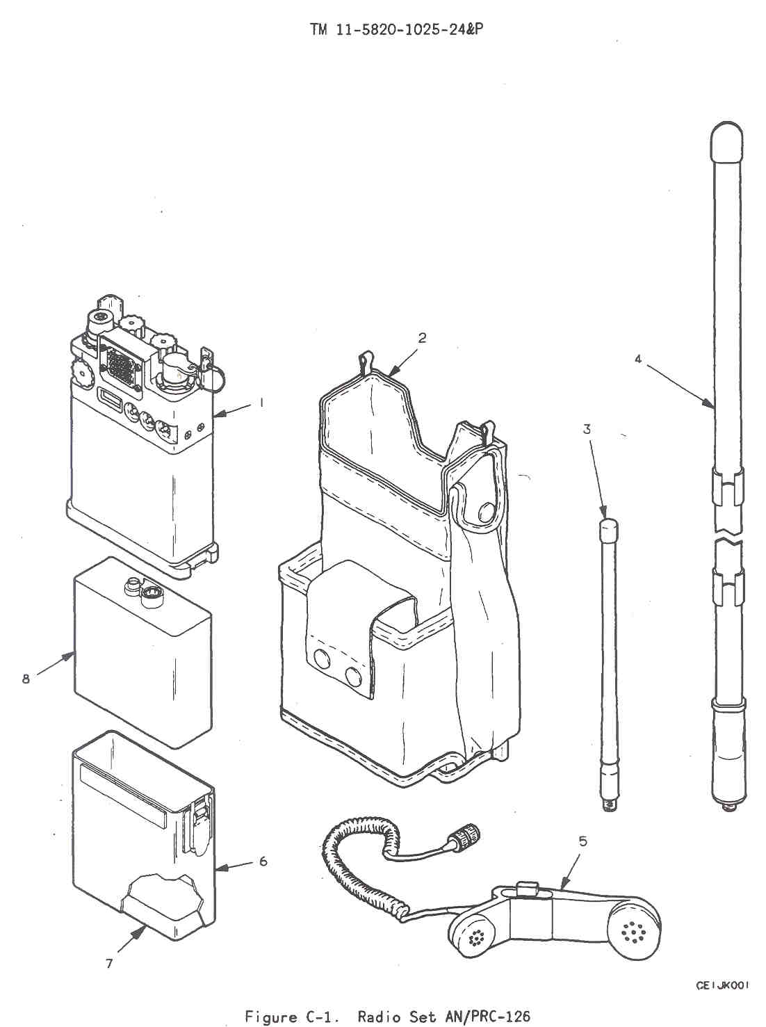
The performed packing, NSN 5330-00-942-5120, in the bottom of your AN/PRC-126 radio set wears out and sometimes falls out. Poor packing or no packing causes battery problems. Check to see if the packing is there, worn or compressed. If it's not there, or if it is worn or compressed so that the battery does not fit snugly, replace it. It's item 7 in Fig C-1 of TM 11-5820-1025-24&P.March 98 PS 544 pg 61 & 459-61 NSNs
AN/PRC-126 Parts
Here are four NSNs that PRC-126 radio users need.
Item NSN Figure AS-4094 short antenna 5985-01-299-0845 Battery Housing 6160-01-298-2408 Carrying pouch 5820-01-255-4068 Antenna matching knob 5355-01-283-6566 C-2 CHAN knob 5355-01-283-6567 C-2 VOL knob 5355-01-283-6568 C-2 483-42 Portable PM Perks - Be sure the retaining clips for the squelch adjusting tool and SVM plug are tight, loose clips can short out the battery.
478-45 Stop Droopy Antennas - bend the antenna the easy way, bending the hard way permanently kinks the ant. (PRC-127 cable NSNs)
476-42 - Keep Radios out of Intensive Care - New battery boxes have side guards on the latches NSN 5820-01-255-4069.
Item NSN Battery Box
w/latch guard5820-01-255-4069 Rubber Batt Box Pad 5330-00-942-5120 Silicone Grease 6850-00-177-5094 Squelch Adjusting Tool
P5.5 of -24&P has
SQ adj procedure5120-01-096-9410 486-42 - NSN Update -
Item NSN Figure AS-3961/PRC-126
antenna5980-01-280-3606 C-1 Dust Cap 5340-01-276-5783 C-2 Corrections to TM 11-5820-1025-10
Page Illus No. NSN Item B-4 1 5985-01-254-9576 AS-4094/PRC-126
short antennaB-4 2 5985-01-280-3606 AS-3961/PRC-126
Long AntB-4 3 5820-01-255-4096 Battery housing B-4 4 5820-01-255-4068 Carrying pouch B-7 1 6135-01-088-2708 BA-5588/U batt. D-3 1 6135-01-088-2708 BA-5588/U batt. D-3 2 6135-01-094-6536 BA-1588/U batt 536-60 - Bad or Missing Battery Packing causes problems -
452-43 - Substitute Dummy Load -
Item NSN DA-437 BNC(m)
dummy load5985-00-089-8990 BNC(m) - Banana adp 5935-00-410-1399 50 Ohm 1W resistor 5905-00-106-9349 Audio/Power Test Adapter
21 Feb. 2002, modified the drawing so it fits on a single A size page.
Working on much improved version that also supports pin-F digital operations.This has the following parts:
The above circuit diagram is from TO 31R2-4_810-3 for the PRC-128.
- Red and Black clip leads for connection to a power supply that can provide 10 to 15 VDC at 0.5 Amp
- U-183 connector on a cord to mate to AUDIO connector J5 on PRC-126
- Momen - OFF - ON switch for the PTT function
- SPKR/MIC switch to select INT or EXT
- BNC(f) connector for receiver audio output
- BNC(f) connector for monitoring the audio signal sent to the radio
Tool Kit TK-101/G
Contains the spanner wrench for the antenna connector.CECOM Supply & Maintenance Bulletin - Vol. 22, nos.2 & 3, Summer/Fall 1996 HEADS UP! (AN/PRC-126 radios)
We want all units out there to know that big brother at DA and the item manager at CECOM are watching you. If you have any AN/PRC-126 radios (R55336) which are above your authorizations, it is time to start your spring cleaning and turn them in. We are in short supply and your fellow soldiers are in serious need of them.The final amplifier transistor may be a MRF-237 that will blow if the radio is keyed with no antenna?For more information or any questions please call the POC, Rosemary Hicks, AMSEL-LC-MMR-A2, (DSN) 992-4825,4826; (fax) 992-4909, e-mail: hicksi@doim6.monmouth.army.mail
Description NSN Figure Item FSCM Part No. Receiver Transmitter 5895-01-256-9639 C-1 1 80058 RT-1547/PRC-126 Carrying pouch 5820-01-255-4068 C-1 2 37695 349924-1 Carrying Harness Sling 37695 348814-2 Lanyard 5985-00-933-2454
SMB 522304 AS-4094/PRC-126 Antenna Short 7" rubber ducky helical
rubber ducky helical5820-01-254-9576
5985-01-096-9396?
5895-01-299-0845C-1 3 37695
63747?513250-1
10231?AS-3575 Antenna Assembly
8.5" Goose Neck
36" Tape measure antenna5985-01-280-3606 5820-00-889-3803
C-1 4 37695 37695
721153-3 Antenna Connector Adapter with BNC(f) 37695 914598-801 Handset 5965-00-043-3463 C-1 5 80058 H-250/U Battery Housing 5820-01-255-4059
5820-01-225-4096?
6160-01-298-2408C-1 6 37695 914153-805 Packing Preformed 5330-00-942-5120 C-1 7 96906 MS9068-024 BA-5588/U Battery Dry Lithium/SO2
replaced by BB-3886135-01-088-2708
6135-01-094-6536C-1 8 80058 BA-5588/U BA-1588/U Battery, Mercury 6135-01-088-2708 C-1 1 BB-588/U Battery, NiCad including housing 6140-01-091-1536
6140-01-241-2295
67237Simple battery Charger Single Station Battery Charger 37695 565604-801 Five Station Battery Charger 37695 706841-801 Bren-Tronics model BB-388A/U 6140-01-419-8190 AP-388/U Battery to Charger adapter (holds 2 batt) 5940-01-427-8601 BA-715 for only the PRC-68,-68A & 68B? PP-8444/U, Universal Portable Charger (UPC) costs $562.52 new
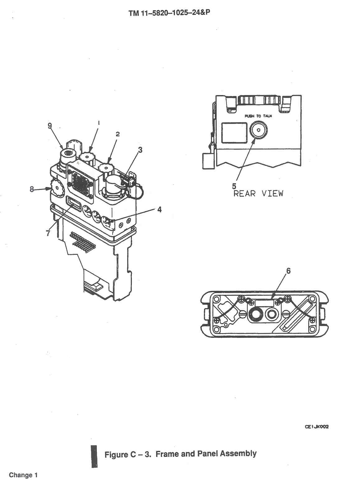
TM 11-6130-489-13&P (075017.pdf) is Restricted on ETM6130-01-427-9110 Data Plate - C-2 1 80063 159828 Squelch Adjusting Tool 5120-01-096-9410 C-2 2 37695 808234-1 Seal, Nonmetalic ST 5330-01-218-8312 C-2 3 37695 345110-1 Module Cover 5820-01-255-4070 C-2 4 37695 918267-804 Low Band Radio Frequency Module 5820-01-257-3142 C-2 5 37695 815586-801 Frame and Pannel Assembly 5820-01-255-5631 C-2 6 37695 816173-821 Dust Cap Assembly 5340-01-276-5783 C-2 7 37695 817455-801 AF/Synthesizer Module 5820-01-255-5630 C-2 8 37695 815587-821 Knob, Channel 5355-01-283-6567 C-3 1 37695 517448-1 Knob, Volume 5355-01-283-6568 C-3 2 37695 517448-2 Connector, AUDIO S935-01-321-8082 C-3 3 37695 186137-5 Switch, Pushbutton 5930-01-208-2271 C-3 4 81073 39-351BLK Push To Talk Button 5930-01-324-3265 C-3 5 37695 165803-1 Jumper Plug, SVM 5935-01-099-0005 C-3 6 98278 095-9003-0024 Frequency, Window Glass - C-3 7 37695 349619-3 Knob, Antenna Match 5310-00-368-4467
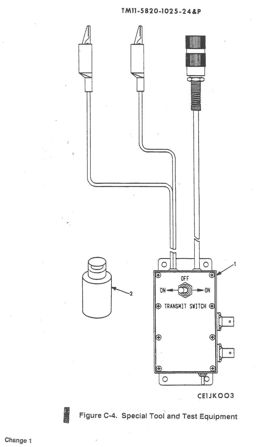
5310-01-283-6566C-3 8 36659 516502-2 Connector, Antenna 5985-01-325-1800 C-3 9 37695 187055-1 Power-Audio Adapter 5820-01-276-0380
5820-01-097-7337?C-4 1 37695 421378-801 Coupler, Transmission (ANT to BNC(f)) 5985-01-097-7337 C-4 2 37695 914598-801 Silicon Compound, 2 oz 6850-00-177-5094 Lint Free Cloth, yard 7920-00-924-5700 TSEC/KYV-2A Secure Voice Module SVM 5810-01-160-4999 PCG-68 - Programmable Code Generator CSD-68 fill gun (Code Source Device?) AN/GRM-114A Test Set
This is an IFR Communications Service Monitor Model 1000S and appears to have no PRC-xxx customization TM 11-6625-3016-14 (051046.pdf) and others are on line at ETM6625-01-144-4486 Vehicular mount/amplifier OF-185 5820-01-301-6301 Tool Kit TK-101/G 5180-00-064-6178 TS-3951/PRM-34 6225-01-094-5646 TS-3354 6625-01-091-3157 Frequency Transfer Cable (Cloning cable) 5995-01-201-1391 568698-801 Repeater cable none 56698-802 OE-254()/GRC Antenna Group 30 to 88 MHz 5985-01-063-1574 RC-292 antenna:
30-36.5, 36.5-50.5 or 50.5-79.95 MHz (not 80 - 88)H-250/U Handset 5965-00-043-3463 5965-01-247-4723 H-138/U Handset H-189/GR Handset 5965-00-069-8886 Ear Transducer (ear mic)
Earphone Transducer (EM-200)
5966-01-187-3079?37695 588088-1
8?2969-80?H-157 AIC modified
Adapterno NSN
no NSN37695
815237-801Vehicular Adapter OF-185/PRC
30 -88 or 130 - 174 MHz depending on amp/fil5820-01-301-6301 901602-801 Diplexer, VHF, CU-2194/URC
limited upper freq of 76 MHz
Radio ports are DC open - not good with PRC-xx51859 755115A0000 Mofified Radio Shack 19-345 Simplex Repeater Controller MXF-340 Vehicle mount w/o DC power
but with remote antennaMOLLE pouch strap system to attach 8465-01-465-2057 Specialty Defense Systems
7.1 Manuals
TM 11-5820-1025-10 (ETM 063550.pdf) - Operators Manual
TM 11 -5820-1025-24&P (MX-63-114B), Ops & Maint Inst. with IPB
Magnavox presales sheet for Ancillaries Cables - showing the cloning and repeater (retransmission) calbes with no bumps, just cables.7.2 Web Links
AN/PRC-68 Legacy by Alan D. Tasker, WA1NYR
PRC Data series by Dennis Starks
U.S. Military Portable Radios by By Alan Tasker, WA1NYR
Collecting Military Radios by Ralph Hogan WB4TUR
The Boneyard Radio Price Guide -
The PRC-25 Story by Dennis Starks
PRC-68-B by megaman
AN/PRC-126, Radio Set at Fort Monmouth
Non Tactical Portables at Army Radios web site
Communications Security and Related Equipment by Frederick W. Chesson -
Additional Comments by Dennis Starks on the Army Radio web page -
BB-388A/U, PP-8444A/U Charger, BA-5588U, 1588U, BB-588U
Datron World Communications MT1060MM 35 W RF booster amplifier, power conditioner, and power supply.
Audio Connectors & Cloning - Fill - Retransmission -
Military Radio Specifications - Radio Set AN/PRC-126 (RT-1547) -
Military Image Files - just a small gif image
*Crossing Linear Danger Areas* - how PRC-126 is deployed in a Squad
Soldiers of Fortune Ltd. - U.S. surplus equipment donated to the Bosnian mission include: 732 AN/PRC-126 handheld radios plus batteries, 1,600 AN/PRC-77 manpack radios with batteries
Ranger Training Brigade - Ranger Handbook TOC - Chapter Seven Communications - some operation and maintenance info
Center for Army Lessons Learned - Communications Equipment - "AN/PRC-126 Squad Radio worked well, especially in MOUT. Minor criticisms noted the audio signal for low battery and other functions which jeopardized position security and the need for an ear piece and whisper mike." - In Praise of Checkpoints - Squad use of PRC-126 and reporting check points - How to Turn Company Morters into a Combat Multiplier - Other small element leaders cannot quickly talk to the mortars without first finding a PRC-119. NOTE: Most squads carry the PRC-126, which does not frequency hop, and is not secure (? what about the SVM?, Brooke comment). This also lengthens mortar section response time.
Physics of Failure - AMXSY-LA UNCLASSIFIED 12 FEB 97 - Re-designs of ICAM, AN/PRC-126 and ARC-210 radios underway
Tobyhanna - Tactical Radio Division - Communications Security (COMSEC) Depot Opertions - Other INFOSEC Links -
C3 in the Maneuver Company -
"Use of non-secure radios (PRC 126/127s) is not allowed until contact with the enemy..." in search engine, but broken link
AN/PRC-117F Special Operations Forces radio has applications for digital divisions and beyond -
ALOG NEWS -Fort Bragg has established a central drop-off point for its 18 units that require repair support for their AN/PRC-126 handheld radios. Fort Bragg mails the radio components to Tobyhanna Army Depot, Pennsylvania, where they are repaired and mailed back to Fort Bragg. This system replaces the former practice of sending the radios through the regular supply system and cuts days off the turn-around time. The program began with the repair of circuit cards but has expanded to include other omponents, such as the PRC-126's frames and panels and its frequency synthesizer modules. Previously, these modules were thrown away rather than repaired.LRC Y2K Spreadsheet - the PRC-126 is Y2K compliant, it does not have a clock
Oral History Interview JCIT 0811LT JOHNSON: Well, get back to training, but again that's one thing that we didn't want to lose; lessons that we had learned. We took time and really wrote up a pretty substantial AAR which we got here. I have already noticed some ... one change come out of it. It was very minor point to put on the tape, but on the PRC-126 the little display panel is in green plastic. The idea behind that is so that it reduces the amount of light when you hit the display light at night. But in actuality, it makes it very hard to read any time either during the day or night. We have been trying to do this for awhile, but we just included in this after action report and that's what brought about the changes and everything. Now there is just clear plastic.Special Operations Forces Posture Statement 2000 - Appendix C Key Programs & Systems - ** Improved weight/size and power consumption by replacing numerous multi-frequency/banded, hand-held radios currently used (i.e., AN/PRC-68, AN/PRC-126, MX-300, MX-300S, and MZ-300R) with one full range/band radio
Specialty Defense Systems - Ranger Assault Carrying Kit (RACK) -7.3 NIIN Text File (NIIN.txt)
This is a file that can be used for searching the DRMS (Defense Reutilization and Marketing Service).
It contains all of the NIIN numbers listed above in the Parts List.7.4 Related PRC-68 Family Radios
The following radios are all in the PRC-68 family and use the same battery and secure voice module. They all use the H-250 handset.
A power increase of 6 dB (1 "S" unit or 4 times the wattage) is just noticable by the human ear, so a radio would need 4 Watts to just be louder than the PRC-126. Why would you want ot carry the weight of a PRC-25 or PRC-77 if you could have a PRC-126? Adding the OF-185/PRC amplifier results in a much more powerful vehicle mounted radio set.
They have a similar physical appearance.- PRC-68 - 30 - 87.975 MHz
- PRC-68A - 30 - 87.975 MHz
- PRC-68B - 30 - 87.975 or 130 - 173.9875 MHz by changing the RF/IF module
- PRC-126 - 30 - 87.975 MHz
- PRC-128 - 30 - 87.975 or 130 - 173.9875 MHz by changing the RF/IF module
- PRC-136 - 130 - 173.9875 MHz
- PRC-25 - 1 to 1.5 Watts
- PRC-77 - 1.5 to 4 Watts
- RT-524 - 0.5 to 8 Watts
- URC101 series - 1.5 to 5 Watts
7.5 Adjustments
Squelch
Remove modle cover and reconnect battery. With panel facing up the squelch control is just above and to the right of the central connector.
8.1AUDIO J5 Pins
I have not been able to find any public information on Cloning or remote programming of the PRC-126 or any other radio in the Squad Radio family.
Some of the following are experiments shed some light on this subject.J5-A (Ground)
J5-B (Earpiece)
Speaker Muting
The PRC-126 J5-B (audio out) is near 0 VDC when the radio is quiet and the DC level jumps to about +6 VDC when the squelch opens. The reason is to sense if an external earpiece is present. If so the speaker is muted.
Remember that the 1/4" phone plug does this mechanically, but with the MIL-C-55116 connectors there is no mechanical switching possible.An AC coupled audio accessory with a high impedance DC voltage controled comparator could be used to detect when the squelch opens and be used for retransmission PTT control.
Pull Down Resistor Value for SPKR Mute
With resistance values greater or equal to 10 K Ohms between J5-B (Audio Out) and J5-A (ground) the radio stays in internal speaker mode. With resistance values less than or equal to 6.8 K Ohms the radio mutes the internal speaker.(For the PRC-68 SPKR mute requires less than 3.3 K Ohms)
J5-C (Push To Talk)
This has the same fuctions as the PTT switch on the radio.J5-D (Microphone Hot)
From J5-D to ground is 150 Ohms. This matches the impedance of the H-250 handset.
This also is what provides the pull down resistance to cause the FILL mode to activate when an H-350 handset is connected.J5-E (DC Power)
This is a power input connection. There is a reverse polarity protection diode in series with this pin going to the OFF-VOL control switch. There is also a series diode between the internal battery and the OFF-VOL control switch. Whichever voltage is higher will power the radio. There may be a resistor in parallel with the battery diode to allow some charging current to go to the battery when external power is applied, but there may not be because non rechargeable as well as rechargeable batteries can be used.Although about 10 VDC appears on this pin when the radio is turned on, it drops to 1.6 VDC with a 1 k Ohm load so is not suitable to power external equipment.
J5-F (Fill - Digital Data)
Grounded
When an H-350/U handset is installed on the Audio connector (J5) of a PRC-126 the LCD shows FILL. This because the H-350/U provides a path to ground for pin F.After the PUSH TO TALK (like to send data out) switch (either on the PRC-126 or the H-350) is momentarily pressed the PRC-126 LCD counts from 1 to 10 and ends with donE, taking aobut 30 seconds. Just before each digit appears in the LCD you can hear a short serial data burst from the microphone (not the earphone) of the H-350. Removing the H-350 connector while donE is in the LCD causes "A3125" to show briefly. The radio never turns on the transmitter because is knows it's in the fill mode.
Note that J5-F needs to be grounded while J5-C is also grounded. You can not ground J5-F, unground J5-F, then very quickly ground J5-C.
Pull Down Resistor Value for FILL
With resistance values greater or equal to 150 K Ohms between J5-F (Fill) and J5-A (ground) the radio stays in normal receive mode.
With resistance values less than or equal to 100 K Ohms the radio goes into FILL mode. (The PRC-68 does not have an F pin.)TTL Data while LCD counts 1 to 10
This data is in the form of 10 packets. Each packet lasts about 50 milliseconds. It takes about 30 seconds for all 10 packets to be sent.
The first bit of each packet is a TTL high that lasts for about 10 mS and pin F is at TTL ground after each packet and prior to the next one arriving.
Rx Signal
When there is no receive signal pin F of the AUDIO connector is at + 4.9 Volts (TTL high) and the AC voltage is zero.
When a signal is being received the DC voltage drops to 3.2 V and the AC signal increases to 2.35 V (indicating digital data).If the SQ DSBL button is pressed J5-F goes to 2.18 VDC and 2.55 VAC (indicating digital data).
It is not clear if this is some kind of data or just TTL noise.
Why is this?The AC could be rectified and used to sense when the squelch is open and be used for a retransmission system.
Tri-State Logic
Pin F seems to have FETs connected to the +5 Volt and Ground rails and can drive rail to rail when in Output mode.
When in Input mode there is a 200 K Ohm pull up resistor to allow sensing when a ground is connected.Data Output Protocol (13 Nov. 2000)
By using the Pico Technology ADC-10 I have analyzed the output data. There may be a slight problem with this low cost way of getting data, if the computer has some task that preempts the ADC-10 it may miss data. To help prevent this use <Ctrl><Alt><Del> and end all tasks except for Systray and Explorer in WIN98SE. Still there was one place where data appears to be missing.I sampled once every 1 millisecond for up to 40 seconds and then trimmed the front and end of the data file.
At the beginning of the file all the leading zeros were trimmed, leaving only a single zero.
At the end of the file all the 2.4 volt readings (where pin F was acting as an input) and all but one of the trailing zeros were trimmed.
The remaining file size is about 26,000 rows of data.
Using Excel (open the data file which was saved with an extension of txt) and use delimited with a space to get it correctly.
Each of the 10 data frames was copied and pasted into a different column (1 through 10) with the first zero to +5 volt transitions aligned.
By looking at the data you can see that there is a start pulse and data separation pulses occurring about 440 mS apart.
It looks like each of the 10 frames consist of 16 bits, 1 start pulse about 3 ms wide and 15 data bits each about 3 ms wide.
The 10 frames correspond to radio channel numbers of 1, 2, 3, 4, 5, 10, 9, 8, 7, 6 in that order, not in the order of the numbers shown in the LCD.
There are 9 Words in each frame:
Rx 10 MHz, Rx 1 MHz, Rx 100 kHz, Rx (0, 25, 50 or 100 kHz),
empty frame,
Tx 10 MHz, Tx 1 MHz, Tx 100 kHz, Tx (0, 25, 50 or 100 kHz).
The first three digits are represented by 4 bits (the remaining 15-4=11 bits are not used) in 1, 2, 4, 8 weighting with positive true logic.
The 25 kHz is handled with 2 bits in 1,2 weighting i.e. 00 = .000 kHz, 10 = 25 kHz, 01 = 50 kHz and 11 = 75 kHz.This protocol can support much more than the PRC-126 uses to output the channel assignments.
Excel file with raw data in the left 2 columns plus processed data.
I helped a fellow in Japan make a PRC-68 family programmer that allows up and down loading the channel settings. It also allows programming the PRC-126 with smaller stop size.
Computer Up & Down loading
PRC - 68B&126&128用インターフェースコンピュ- - Manual -
MX-18290 on PRC-126
P1 will mate but does not cause the PRC-126 to go into fill mode. Opening the MX-18290 box shows why, pins F and B of P1 are not connected to anything.
P1 is the connector that is used to fill the MX-18290 and J1 plus a 1:1 U-229 cable is used to fill the radio.
Doing this test using J1 and a 1:1 cable may give different results, but I don't have the 1:1 cable.8.2Working Cables
8.2.1 Cloning Cable 11 Dec. 2000
The cloning cable is wired as shown below:This works on both the PRC-126 and PRC-68B and should also work on the PRC-128 and PRC-136.
- (ground) A ------ A (ground)
|- 47 K Ohm Resistor between A and F
|- (FILL) F--------F (FILL)
This is a symmetrical cable so that the radio that has PTT pressed becomes the master and the other radio gets reprogrammed.
27 Jan 2001 - to make the Cloning Cable I used the U-183 connectors from two "RT-1209/PRC-104 to KY-99" cables that are offered on eBay. The cable clamp is available from Newark as their p/n 96F4915. Alpha Wire 1176C (DS-760914) is a six conductor cable that Newark also stocks.8.2.2 Retransmission (Repeater) Cable 15 Dec. 2000
The retransmission cable is wired as shown below:
This is a symmetrical cable so that whichever radio first hears a signal turns on the other radio (PTT) which acts as the transmitter.
- (ground) A ---blk----- A (ground) (optional external power goround)
- (ext Ear) B ---blu----> D (mic)
- (PTT) C <---grn----F (FILL)
- (mic) D <----org----B (ear)
- (Ext Pwr) E ---red--- E (Ext Pwr) (optional external power + 12 to 17 VDC)
- (FILL) F ----wht----> C (PTT)
More investigation needs to be done regarding the setting of the VOL control on both radios.
The PRC-68 can be used as a transmitter in a repeater setup and probably any radio with PTT could be used as a repeater transmitter..
More testing needs to be done to see the effects of desense depending on separation and frequency difference.
This needs to wait until I make up a longer cable.
27 Jan 2001 - Retransmission/Repeater Cable - Used a 1N4744 15 Volt Zener (RS276-564) with the cathode band to red (pos supply) and in series with a 1N4001 (RS276-1101A) with it's cathode end to black (ground). The 1N4001 is there to raise the clamp voltage by about 0.6 volts. This is to prevent the external supply from exceeding a little over 15 Volts. If it does the zener will conduct drawing a lot of current protecting the PRC-126.External Power Option
In both of the above cables (Ext Pwr) E could be wired to (Ext Pwr) E and that lead brought out for external power of both radios.
For the cloning cable there is not much point, unless many radios were being done in a shop environment where batteries were not desirable.
For the Retransmission cable it would make some sense to use the E to E wire for external power so that the repeater/retransmission system could run for a long time.Using the external power option on both radios and also using a CU-2194 would allow both radios to be interconnected using a short retransmission cable and the use of a common antenna.
U-183 Connector with Strain Relief - the start of a set of cables
8.3 Drive Testing
By using the Radio Shack 19-345 I can have one radio at my home acting as a repeater and then use another radio in my car to see what coverage I have. This is very dependent on the antenna used for the repeater and for the mobile unit. Unlike a retransmission or repeater, this setup allows you to talk to yourself. This is great for this type of testing.My first try was to put a PRC-126 upstairs with the long antenna 19-345 to act as a repeater. Then drive with another PRC-126 using the ducky antenna. I could only hit the repeater for about 1/2 mile, but could hear it for many miles.
Next is to use the OE-254 with just the lower sections for the repeater and use the long antenna for the mobile.
With the OE-254 setup using only the lower section masts (maybe 15 feet up) the range more than doubled, maybe a mile for two way communication.
18 March 2001 - base and mobile ant info on OF-185 RF amplifier web page
Using Hamstick 9106 on a Diamond K400-3/8C 2-axis adjustable mount on the car is a noticable improvement over the PRC-126 ducky or tape measure antenna, but has limited bandwidth.Put the OE-254 back up after polishing all the joints and re-assembling using Radio Shack Lube Gel and coax seal on all 19 connections. The mast is at full height. This has made a big difference. The two way range is now many miles, most of the Ukiah valley! This may be due to the doubled height or cleaner joints, or both. In some cases the OF-185 in the car can be switched to BYPASS (running the PRC-126 bare foot) and still have many miles range.
8.4 Crystal Frequencies
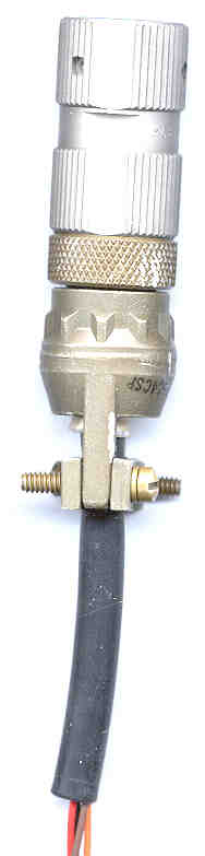
Measured by connecting 914598-801 antenna adapter (or use my 68AA Antenna Adapter) and cabling to Agilent 4395A spectrum analyzer.
PRC-126 s/n BJ10442A:
6.399962217 MHz @ -106 dBm = 6.4 MHz synthesizer crystal
21.854983125 MHz (21.855 MHz = 21.4 MHz + 455 kHz) @-135 dBm mixer crystal
There are many signals around - 125 dBm that obscure the 76.8 kHz microcontroller crystal.
307.225 kHz ( = 4 * 76.8 kHz) @ -138 dBm microcontroller crystal
Back to Brooke's Products for Sale, Audio Connectors & Cloning - Fill - Retransmission, Squad Radio, Military Information, Electronics, Personal Home, PRC68.com page9.1 Provision for charging battery connected to radio
This could be done by adding a resistor in parallel with the voltage steering diode that is now between the battery and the OFF switch.
Something like 470 Ohms would provide trickle charging for the NiCad battery while vehicle or external DC power was supplied.
This may not be a good thing to do if primary batteries are used.9.2 Provision for programmable sub audible tones
With only the 150 Hz tone normal ham repeater operations are not possible. Different tones might be possible if a new micro controller was installed since the tone is generated inside the micro controller. The channel programming sequence could be modified to allow for entering a tone frequency.9.3 Provision for smaller Frequency Steps
This may be possible if a new micro controller was installed. I am guessing that the PLL synthesizer chip would support much finer steps and is probably controlled by a serial data stream.9.4 Provision for Tx Frequency output on the "F" Pin
If the radio were to send it's Tx Frequency as digital data on the "F" pin whenever the CHAN was changed, then a smart accessory could use that to program an antenna like the AS-1729. Better would to send the Tx frequency whenever the PTT was activated, i.e. just prior to a transmission.9.5 Antenna Adapter with built in Resistor available as my 68BA
There are many things that you might want to connect to the radio that are 50 Ohm RF loads but do not have less than 2,000 Ohms DC resistance to ground. It would be much more useful if the Antenna Adapter had a built in 1,000 Ohm resistor.9.6 Scan Function
An external microcontroller could be connected to the AUDIO connector and program the frequency of a single channel that was the channel selected by the CHAN knob. After setting the frequency the Fill line would be sensed to see if a station was there. If no station, then stop to next frequency. When a stations was found it would be programmed into one of the remaining channels. If more than 9 stations were found the extra channels could be stored in the external Scan box and banks of 10 could be loaded into the radio upon a command.
This is the [an error occurred while processing this directive] time
this
page has been accessed since 29 Oct. 2000.