VIC
Vehicle Inter Communication
&
VRC-12 Series Radios
© Brooke Clarke 2004 -
2023
VIC Background
VIC-1 System Boxes
AM-1780
C-2296 Outside Control Box
C-2297 Driver's Control Box
C-2298 Commander & Crew
Control Box
C-2299 Radio Relay Control Box
C-2742 Channel Selection Box for
RT-246
C-10374 VINSON Radio Relay Box
MW Cables
VIC-3
Description
Manuals
Comments
Cables
Boxes
VRC-12 Series Radios
RT-524 Speaker
RT
RT-246
Pushbutton RT
R-442 Aux
Receiver
X-mode
VRC-53 & VRC-64 Radios
Manuals
Introduction
Most of the documentation on the VIC-1 equipment is in
the VRC-12 Series Radio manuals so I have combined them on this
web page.
Since the MT-1029 Mount, which is a
part of all VRC-12 series radio systems, is also used with other
radios it's on a seperate web page that also has information on
the VINSON compatable versions of the VRC-12 system.
VIC Background
The W.W. II time frame inter-phone
amplifier may have been the BC-605.
VIC-1
In vehicles that are served by a crew, like a tank, where each
crew member needs to have intercom access to the other crew
members or to a radio the VIC system is the standardized method of
accomplishing the communications.
The VIC-1 system was introduced to work with the VRC-12 Series of
radios that use the RT-246, RT-524 and R-442, the
VRC-53/GRC-125 (PRC-25), the
VRC-64/GRC-160 (PRC-77), and a number of
other radios. For example in the
GRC-213
(PRC-104) system, the AM-7152 Audio Amplifier/Power Supply
has the normal mount type of military vehicle connectors.
The VIC equipment can be used for plain text radio communications
or with encrypted (
VINSON) communications
since all the signals carried by the VIC components are DC and
plain text voice. The VIC cables to the crypto junction box,
not the normal
radio mount VIC
connector when crypto equipment is in use.
The AM-598 Audio Amplifier/Power Supply used with the PRC-8, PRC-9
and PRC-10 does not have provision for use with an intercom
system, so maybe the VIC-1 started with the VRC-12 Series radios?
Integrating
VIC-1 with other equipment by Chris Story
VIC-5
FFCS boxes are more intelligent and have their own
displays. The big push for the VIC-5 system is that it also
supports Ethernet for VOIP - C. Alexander Leigh
SINCGARS
The SINCGARS mounts support the
VIC-1 system.
The dual radio mount is connected AM-1780-J501 to J3 and
AM-1780-J503 to J4.
The single radio mount is connected AM-1780-J501 to J3.
Ref: TM 11-5820-890-10-1 pdf pg 121-122.
TM 11-5820-890-20-2 Chapt 2 Operational check tables and
Troubleshooting tables (165 pages)
VIC-1 System Boxes
AM-1780, AM-1780A, AM-1780B Amplifier
J509 & J511 for use with C-2299 Radio
Relay Box
J501 to "A" radio
J510 to "B" aux receiver
J503 to "C" radio -or- J508 to "C" aux receiver
J504 to commanders C-2298 Control Box
J506 & J507 to crew members control boxes
J505 to drivers Control box or a crew members control box
C-2296 Outside Control Box
Connects to C-2297 Drivers Control
Box. It has volume control and a RAD TRANS-INT switch and
permanently connected handset with a coiled cord. Also a
receptacle for connection to an external call lamp.
The metal box that holds the C-2296 is NSN 5965-856-6219
"Handset Box Assy" It has an indicator light pointing up on the
front surrounded by a metal shield.
TM 11-5820-401-35-6, Direct Support, General Support, and Depot
Maintenance Manual Including Repair Parts and Special Tools List
for Control, Intercommunication Set C-2296/VRC (FSN:
5820-892-3337), Nov 1973
TM-9-2350-230-12 M551A1 152mm gun.
C-2297 Driver's Control Box
Looks very similar to the C-2298
but has a added SIG-EXT-OFF switch and indicator light that are
both associated with the C-2296 Outside Control Box. When
the switch is set to SIG the call light on the external box is
turned on (similar to ringing a phone, but you could not hear
this phone ring). When in the EXT position the Outside
Control Box is connected into VIC-1 system. When in the
OFF position the Outside Control Box is disconnected from the
VIC-1 system and the outside PTT switch lights the Indicator
lamp on the Driver's Control Box.
C-2298 Commander & Crew Control Box
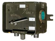
The
switch positions are:
All - listen to A radio, B aux rcvr & C aux rcvr, Talk and
listen on intercom, Tx on A radio (only when no intercom traffic).
A -listen to A radio, Tx on A radio, talk and listen on intercom
(radio or intercom is selected by switch on haadset).
Internal Only - talk and listen on intercom
B - listen to B aux rcvr, Tx on A radio, talk and listen on
intercom
C - listen to C radio or C aus rcvr, Tx on C radio, NO intercom
function.
The function of this box is slightly different depending on how
it's connected to the AM-1780.
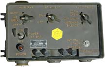
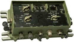
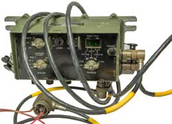
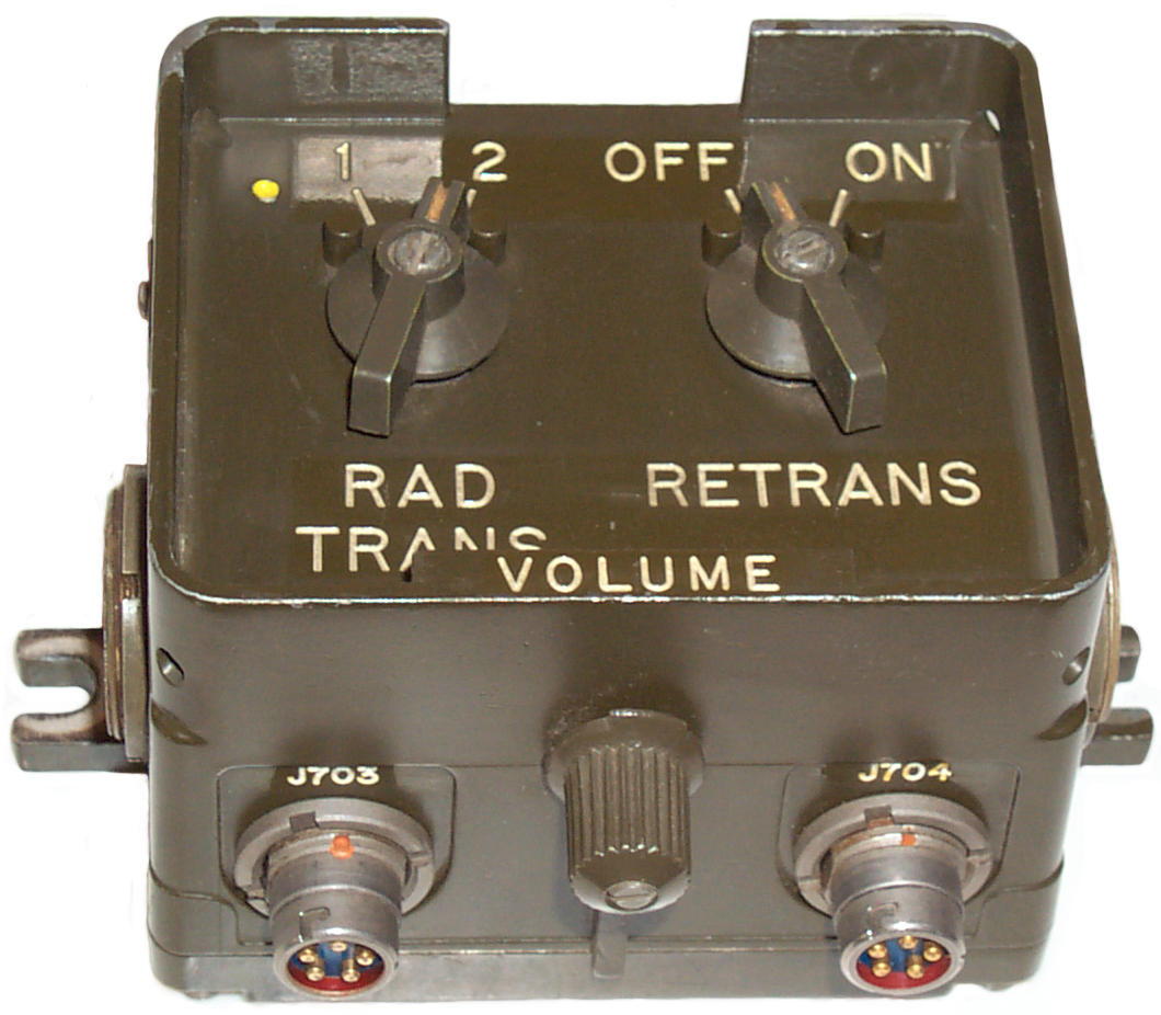
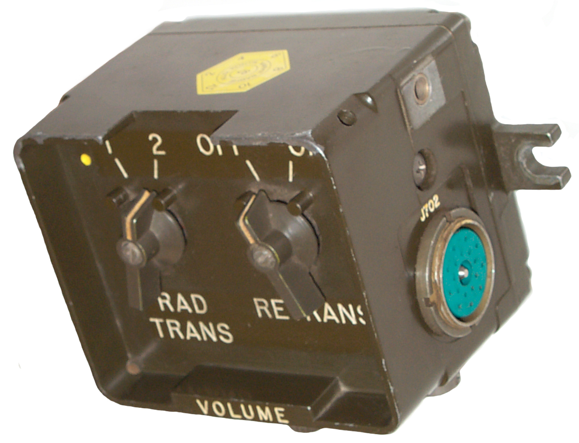
C-2299 Radio Relay Control Box
This box can be used with the
AM-1780 or used with just radios and no AM-1780. For
example if a retansmission system was in a jeep or
HMMWV there would be no need for the
AM-1780 so just the C-2299 would be used.
 |
 |
 |
J701
Left-Front-Bottom
|
J703
Bottom-Front J704
|
Right-Front-Top
J702
|
The left "RAD TRANS" switch controls which radio you transmit
from using a handset or mike connected to one of the C-2299
audio connectors. The right "RETRANS" switch turns
retransmission either ON or OFF. The VOLUME control only
effects the loudness of a locally connected handset or speaker.
Note ONLY the radio connected to C-2299-J701 is supplying
power the the mike amp in the C-2299. So if you want to
use a handset connected to C-2299-J703 or J704 the radio
connected to J701 needs to be powered. There is no
DC path from J702 to the mike amp so even though you
connect a powered radio to J702 and set RETRANS off and RAD
TRANS to 2, you will NOT be able to get mike audio to the
radio. You will however be able to key the radio.
This is normal and does not indicate a problem with the
C-2299.
A simple modification would be to put a couple of series diodes
from both J701 and J702 to the mike amp so either side would
power the mike amp.
For my taste the handset speaker volume is low when connected to
either J703 or J704 with the volume control all the way to
max. This may be due to differences in the RT-246/RT-524
and the PRC-77 or GRC-213 audio out signal levels or
impedance. R703 in the C-2299 is a 150 Ohm resistor that
is the impedance load for either radio's audio and may be too
low a value. This also may be why the audio coming from
the transmitter seems weak.
Note: A long time ago when 1/4"
phone plugs were common it was easy to have switching that was
activated by inserting/removing the plug into/from the
jack. I used this switching to disable loudspeakers in
radios and TVs when headphones were inserted into the jack.
When the military went to the U-77 and now the U-229 type
audio connectors you can no longer use mechanical means to
detect that the audio accessory is connected. Instead a
small current limited DC voltage is output along with the
audio signal and the current is sensed in the
PRC-68 family of radios to know
when to mute the internal speaker.
The C-2299 does not have this audio accessory sensing
circuitry and so might be over loading the audio line.
Maybe this is why there are not many of these boxes around?
Retransmission
Retransmission is similar to a
repeater, but with a huge difference. Retransmission is
a two way system whereas a repeater is a one way system.
Cross Band Retransmission

One of the big
advantages of retransmission is that it allows cross band
communication. For example if a
VRC-64/PRC-77
VHF low band radio is connected to a
GRC-213
HF radio using the C-2299 Retransmission box. Then someone
within range of the VRC-64 can use a hand held
PRC-126 radio to make simplex contacts
on HF radio.
The California Highway Patrol uses a retransmission system in
their patrol cars. The radio link from base to car is by
means of a VHF low band. The officer carries a VHF high
band radio when out of the car that has the VHF low band base
station retransmission linked.
Note that the power supply to the system only needs to have
current capacity of the highest current transmitter plus the
other band receiver. Never are both transmitters on at the
same time.
I wonder if there are other radio systems that have the VIC-1
connector that could be used for other bands?
Stand Alone
This box can be connected between 2 MT-1029 mounts directly to the
J-22 connector on each mount. No AM-1780 is needed for a
retransmission setup. When the RETRANS switch is OFF then
the other switch selects which RT the handset on the C-2299
controls and hears.
TM 11-5820-401-35-1 Control, Frequency Selector C-2742/VRC and
Control, Radio Set C-2299/VRC, April 1973
VIC-1 Integrated
The C-2299 can also be connected:
C-2299-J-702 to AM-1780-J-509 and
C-2299-J-701 to AM-1780-J-511
Reference TM 11-5820-401-35-1 Fig 3-1 System Applicatin of
C-2299/VRC
Audio Extension
In TM 11-5820-401-10-1 which is for wheeled vehicles (no crew)
& -2 which is for crew served vehicles with VRC-12 radios and
VIC-1 intercommunication systems, the C-2299 is shown as a simple
way to provide remote connection of audio accessories.
Note: This can be done
without the use of the AM-1780. There's no intercom
function, just a remote of the radio's mike and speaker or
headphones with a volume control. This is described in TM
11-5820-401-10-1 for wheeled vehicles w/o the VIC-1.
C-2742 Channel Selection Box for RT-246
This box is only used to select the
channel and power level of the RT-246 and does not interconnect
with the VIC-1 system. A number of these boxes can be daisy
chained. There is a momentary push button on the box which
when pressed and released makes that box the one controlling the
radio frequency (channel selection) and can also set low or high
output RF power level.
C-10374 VINSON Radio Relay Box
This is the box to use when the
Retransmission system will be handling encrypted
communications. It may have a wider audio bandwidth like the
HYX-57 does when compared to the
GRA-39, or it may have better
TEMPEST
shielding, or both (just guesses).
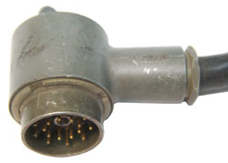
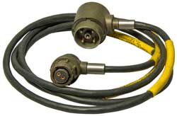
MW Cables
There are two types of cables used
with the VRC-12 series vehicle systems. The 9 and 18 contact
MW series. In addition there are the
DC Power cables as shown on the MT-1029
page.
There cables are associated with the vehicle mount, like the
MT-1029.
9 Contact MW Series
|
|
MW20F(M)B00
|
|
18 Contact MW Series
MW10M(M)D11
|
|

MW20F(M)D00
|
|
VIC-3
This section on the VIC-3 was updated with the help of Mike
Murphy. VIC-3 supports Active Noise Reduction (ANR)
headsets.
The power supply is the standard military vehicle 24 VDC (18 -
22 VDC) and can draw up to 2.6 Amps depending on the system
configuration.
The interface between stations is digital Biphase modulated at
2.56 Mbps, 10 Vpk-pk (max, 2 Vpk-pk (min).
The field wire interface is compatible with the VIC-1 AM-1780 and TA-312 analog
field phone.
The radio interface is compatible with the SINCGARS (SINCGARS, RT-1439, RT-1523),
GRC-213, VRC-12.
Description
The follow on system to the VIC-1.
Has a Master Control Station (MCS), Full Function Crew Station
(FFCS), Radio Interface Terminal (RIT), Monitor Only Station
(MOS), Loudspeaker (LS). Many of these boxes use the same
mounting hardware and the VIC-1 boxes.
Manuals
TM 5830-263-10 (
TM-11-5830-263-10.pdf)
TM 5830-263-20&P (
TM-11-5830-263-20-and-P.pdf)
TB 5830-263 -xx where xx is the dash number for a installation in
a particular vehicle.
Comments
The VIC-3 does not use 2-conductor wiring.
The highway cables (between the FFCS and MCS) are 7-wire.
The cables between the MCS and the radios are 6-wire. Also,
the system is not digital. The audio is analog as with
the VIC-1. Digital signalling is used to carry PTT and
mode select messages, but the audio is analog. The
system is "programmed" to know its topology so if a
station is missing or an extra one is added the MCS can
display an error.
The audio transmitted between the FFCS
crew boxes is indeed digital. That is how audio
permission for each radio can be applied to each crew
station. There IS a wire dedicated to analog audio in
the highway cable and this is only used by the MOS
monitor only stations. Why they decided to do it this
way is of course a mystery.
TM 11-5830-263-20&P has a very
useful description of the cable construction and box
operations.
Cam
22 May 2017
Some other tidbits that you might want to mention are the
fact that the U228 connectors on the FFCS carry power on
the extra pin. I believe this is the pin that is used for
fill in single-port SINCGARS radios. The purpose of this
is to power the ANR units in the Bose headsets which are
intended for this system. However, other radio accessories
that are normally compatible with single-plug U228 work,
eg, H250, peltors, etc.
The VIC-3 can be configured in either a ring configuration
or a branch configuration. In the former the FFCS boxes
are connected in a ring to the MCS. This allows the system
to keep functioning if a cable or FFCS breaks, which it
will detect (the MCS displays the fault).
Unlike the VIC-1, the VIC-3 MCS cannot parasitically take
power from a radio. It needs to be powered from the power
port. The MCS has provisions for 2 radios, and then 4 more
can be added via a pair of RIT boxes - the system is full
at 6 radios.
The VIC3 is also known as the ROVIS. The hardware is the
same - it is compatible - but the ROVIS is the "export"
version. There is another flavor of ROVIS called the LV2.
In this system the MCS is doubled up with a FFCS (and the
same small size as a FFCS). This allows the system to be
installed in a much smaller footprint, ideal for smaller
vehicles like ATVs or Jeeps.
Another tidbit which people seem to run into is the power.
The cables goes to a radio tray same as a VIC-1 and is
that big 4-pin connector. On the VIC-3 though the pinout
is "backwards". A carries +24V and B carries GND. What
throws people off is GND is floated to the regulator
whereas the shell of the connector is the chassis ground.
So the correct wiring is +24 to A (WHITE) and GND to B
(BLUE) AND SHIELD. Thankfully the MCS Is reverse polarity
protected.
VIC - Vehicle Intercom System
FFCS - Full Functional Crew Station
MCS - Master Control Station
PTT - Push To Talk
SINCGARS - Single Channel Ground / Airborne Radio System
U228
- Military Standard Radio Headset Connector
ANR - Active Noise Reduction
ROVIS - Royal Ordnance Vehicle Intercom
System
LV2 - ???
- C. Alexander Leigh
July 2016
Photos
of VIC-3 Installation in LMTV truck (Wiki).
|
VIC-3 Cables
TM 11-5830-263-20&P starting at pdf page 150 labeled A to
V.
App H, pdf page 223 Connector Pin ID & Signal Names.
Note the 4-Pin Power plug has standardized wiring that goes
back to at least the MT-1029 - CX-4720 cable:
Pin
|
Wire
|
Function
|
A
|
Black
& Green |
Negative |
B
|
Red
& White |
Positive
|
C
|
|
|
D
|
|
maybe
gnd for On |
|
CX-13468
4-pin end
Power COnnector Inc. 18-708 OCS66 0136
Connector P2 mates with power connector on radio mounting
tray
Cable Assy - Pwr. Elec p/n A3206017-7 Date - 10/01
Connector P1 mates with MCS Power Connector
Thorn 10-2
|
Power
-24
|
A
|
B
|
+24
|
B
|
A
|
|
C
|
nc
|
|
D
|
nc
|
|
|

|
CX-13470
PCI 18-187N OCS66
31461-A3205990 0701
Connector P1 mates with Station connector
CX-13470/VRC(10 feet. 0 inches)
W15P7T-06-F-0029 Mfr 65242 NSN
5995-01-406-1171
Cable assy - Spcl Prp. Elec pn A3206018 - 10 Date -
04/07
Connector P2 mates with Station Connector
PCI 18-187N OCS66
31461-A3205990 0701
|
Highway |
|
|
CX-13492
|
Speaker
|
|
|
5995-01-512-5625
|
Radio Audio
|
|
VIC-3 Boxes
Highway Cable A3206018
Always P1 to P2 the 7 pins are wired 1:1.
This system can continue to operate even when there are certain
types of failures, like a cable being severed.
Pin
|
Function
|
1
|
+28V PS
|
2
|
PS return
|
3
|
Data+
|
4
|
Data-
|
5
|
Analog Audio
|
6
|
+24 ANR
|
7
|
ANR return
|
MCS CD-82/VRC Master Control Unit
Fig 1
|
Fig 2
 |
Fig 3 Test Fail
|
The Power connector is marked: AB05 1002PC 34A5872 ABM0829
TT Electronics AB05 connector datasheet (ab05-951972.pdf)
decoded:
10: cable connecting receptacle
02: ?
P: Pins
34A5872: ?
ABM0829: ?
FFCS C-12357 Full Function Crew Station
MOS C-12358 Monitor Only (Crew) Station
RIT C-12359 Radio Interface Terminal
LS LS-688
Loudspeaker
VRC-12 Series Radios
Legacy radio system retired from Army Guard
Nov 20, 2008
BY Staff Sgt. Jon Soucy

ARLINGTON, Va., (Army News Service, Nov. 20, 2008) -- After more than 50 years in service, the venerable AN/VRC-12 series radio was retired from the Army National Guard in a ceremony Nov. 18 at the Army National Guard Readiness Center.

For many, the retirement is symbolic of many other changes that have taken place within the Guard over the past few years.

"This is really a symbol of us transforming to an operational force," said Maj. Tony Caldwell, the Army National Guard battle command team chief. His team oversaw the phasing out of the '12'-series radio systems.

First introduced in the 1950s, the 12 series radios were used extensively in Vietnam and retired from the active component in the late 1980s in favor of the Single Channel Ground and Airborne Radio, more commonly known as the SINCGARS, said Caldwell.

The 12 series radios were still common in the Guard and Reserve in 1991 during Operation Desert Storm. And for those called to active duty for that conflict, once on the ground in the Middle East, communications became a problem.

"It was difficult for those with the older radios to talk with those using the SINCGARS," said Caldwell.

Throughout the ensuing 17 years since the Gulf War, the SINCGARS radio was phased into the inventory of Guard and Reserve units, but it wasn't until recently that all remaining 12 series radios were replaced, said Caldwell.

The replacement of the radios also represents a change in the way units are supplied with equipment.

"There's been a real change in the last few years and if you hadn't been around before, you wouldn't appreciate it," said Col. Harold Greene, deputy director for material at the Department of the Army.

In the old system, there was a tiered readiness level with certain units getting newer equipment first, said Greene. "I can tell you absolutely, today, we don't do that in any of the components."

Now, said Greene, units are equipped based solely on their Modified Table of Organization and Equipment, the document that lists out what equipment and people and how many of each units should have, regardless if the unit is active or reserve component.

"Certainly, as we go through deployments in support of the Global War on Terrorism, we don't distinguish between components in how we use those troops (in those units)," said Greene.

The SINCGARS has many improvements over the 12 series radios such as a greater range, greater battery life and the ability to hop between frequencies, which results in greater security of radio transmissions.

But, for many, the 12 series will always occupy a certain place in their heart.

Brig. Gen. Leodis T. Jennings, special assistant to the director of the Army National Guard, said his greatest memory of the 12 series radio was using it while attending the Primary Leadership Development Course as an E-4 at Fort Lewis, Wash.

There, students used 12 series radios as they rotated through positions in a squad while on patrol.

"It (radio operator) got to be the position I hated the most," said Jennings. "Every time the patrol leader did something or went somewhere you came running with this radio on your back and you would hand it to him and it didn't work. And he would say, 'What have you done to the thing?'

"And, I don't recall ever doing anything to it. More often than not it didn't work. You were carrying extra batteries and it was heavy. I don't know how long the batteries were supposed to last, I think we were told eight hours, but if you had one that lasted two hours you were doing good."  (Brooke:  Note this is not correct the VRC-12 radios are NOT man portable!)

Short battery life and a penchant for overheating are things that stick in the minds of many who remember the radios, said Caldwell, who as part of an artillery unit used to have his Soldiers place wet sandbags on top of the radio units to help keep them cool.

Despite those obstacles, Guard members still met the mission. "Even though this was a capable piece of equipment, it was not the best radio, but we in the Guard made it work," said Jennings.

And for those currently serving and using outdated equipment, Greene says be patient.

"Hopefully, we've now set the system up so that it won't be these relics of the past, of my past as a young officer, that hang on out there in the farthest reaches of the National Guard. And that we've got everyone modernized ... across the entire force," said Greene.

(Staff Sgt. Jon Soucy writes for National Guard Bureau)
TF
11-3305 Radio Set AN/VRC-12, 1963 - RT-66, RT-67, RT-68 are
replaced by VRC-12 which consists of: RT-246, RT-524, R-442
another link to the same file in two parts.
Radio Set AN/VRC12 pt1-2
1963 US Army Training Film
Radio Set AN/VRC12 pt2-2
1963 US Army Training Film
The "VRC-12 Series" of radios is is the shorthand way of saying
each of the following vehicle radio set names. These radios
are supposed to have an annual alignment Ref June '94 PS mag
499 pg 5 and TM 11-5820-401-20-1 Paragraph 3-5.
|
VRC-12
|
VRC-43
|
VRC-44 |
VRC-45 |
VRC-46 |
VRC-47 |
VRC-48 |
VRC-49 |
VRC-53
GRC-125
|
VRC-64
GRC-160
|
RT-246
|
1
|
1
|
1
|
2
|
0
|
0
|
0
|
0
|
-
|
-
|
RT-524
|
0
|
0
|
0
|
0
|
1
|
1
|
1
|
2
|
-
|
-
|
R-442
|
1
|
0
|
2
|
0
|
0
|
1
|
2
|
0
|
-
|
-
|
PRC-25
|
-
|
-
|
-
|
-
|
-
|
-
|
-
|
-
|
1
|
0
|
PRC-77
|
-
|
-
|
-
|
-
|
-
|
-
|
-
|
-
|
0
|
1 |
I've shown the VRC-53/GRC-125 (PRC-25
based) and VRC-64/GRC-160 (PRC-77 based)
systems in the table but they probably are not technically part of
the VRC-12 series.
All of the above radio systems make use of either the MT-1029 large Mount or the MT-1898 Mount
for the R-442 receiver.
These radios came out about the same time as the PRC-77 and
included provision for X-Mode operation, which at introduction was
by means of the Nestor KY-8, KY-28 or KY-38
Secure Voice system, later the VINSON system was used with
the VRC-12 series radios where the KY-57
was the common Transmission Security Device.
The RT-524 or RT-246 or AM-2060() all
mate with the MT-1029 Mount.
Both the RT-524 and RT-246 when used by themselves can only
operate in half duplex mode, that is Push and hold to talk,
release to listen.
RT-524
This radio is about the same physical size as the
AM-2060 with either a PRC-25 or PRC-77 mounted. It is a
single channel radio with frequency setting using controls very
similar to the PRC-25 or PRC-77. It has a built in
speaker. The power output can be either __?__ or 30?
Watts, considerably more than the output of the PRC-25 or PRC-77
which are only a few watts. But note this extra power only
comes into play when the vehicle is sited on a hill or an
external antenna like the RC-292 or OE-524 is used.
This radio uses many of the same internal modules as
the RT-524 but instead of a speaker it has push buttons for
selecting one of 10 preset operating frequencies. The
physical size is the same as the RT-524. This radio allows
remote selection of the operating frequency using one or more
C-2742 Remote frequency control boxes.
R-442
This is a receiver only referred to as the "auxiliary
receiver". As shown in the table above it's a part of a
number of the VRC-12 Series radio systems.
Capability of the various VRC-12 Series systems
The following systems contain only a single RT:
VRC-43, VRC-46, VRC-53/GRC-125 and VRC-64/GRC-160. These
systems can only be used in half duplex mode.
Systems with at least one RT and either one or two Aux
receivers: VRC-12, VRC-44, VRC-45, VRC-47, VRC-48, and VRC-49
can be used in the full duplex mode which is just like a
telephone where you can speak and hear the other person at the
same time. There are restrictions concerning seperation of
operating frequencies and distance between antennas for this to
work. This is not to say that these systems were used that
way, just that it's possible.
The VRC-48 and VRC-49 systems contain both the AM-1780 and
C-2299 and are designed for retransmission opertion and need to
obey the same rules about frequency and antenna seperation.
X-Mode
The X-mode connector on the VRC-12
series radios is NOT the same mechanically as the POWER
connector on the PRC-77. The jumper cap must be in place
for plain text operation since it has 3 jumpers.
Pin
|
Function
|
A
|
X-mode
in (Rx)
|
B
|
nc
|
C
|
X-Mode
Out (Rx)
|
D
|
150
Hz Tone in
|
E
|
X-mode
in (Tx)
|
F
|
Ground
|
G
|
X-mode
out (Tx)
|
H
|
nc
|
J
|
150
Hz Tone out
|
K
|
PTT
|
Cap jumpers:
A to C
D to J
E to G
VRC-53 & VRC-64 Radios
Related Equipment
MK 992/VRC-12 Module Kit
Contains a set of modules and the
VRM-1 test meter along with a power cable.
TM 11-6625-496-12, TM 11-6625-496-45, TB
11-6625-496-35 are the manuals covering the VRM-1.
Manuals
The following manuals include VIC-1 onfo, but are not
specific to the VIC-1 system.
VRC-12 Series & VIC-1
TM 11-5820-401-10-1
This is the operator's manual for wheeled vehicles
Radio Sets: AN/VRC-12, ... AN/VRC-49 where the interphone system
is typcially not used. It does include the use of:
- RT-246
- RT-524
- R-442
- C-2742
- C-2299
TM 11-5820-401-10-1HR
This is the Hand Receipt manual for wheeled
vehicles. It's 102 pages with information on which install
kits are used for which radio in which vehicle.
TM 11-5820-401-10-2
This is the operator's manual for tracked
vehicles Radio Sets: AN/VRC-12, ... AN/VRC-49 where the
interphone system is typically used. It does include the
use of:
- RT-246
- RT-524
- R-442
- C-2742
- C-2299
- AM-1780 and all the above VIC-1 boxes.
TM 11-5820-401-10-2HR
This is the Hand Receipt manual for tracked
vehicles. It's 296 pages with information on which install
kits are used for which radio in which vehicle.
TM 5820-401-20-1
Is the organizational Maintenance Manual for wheeled
vehicles. 384 pages with lots of details.
TM 5820-401-20-2
Is the organizational Maintenance Manual for tracked
vehicles. 637 pages with lots of details.
Para 1-26 & 1-27 have a lot of VIC-1 theory
TM 5820-401-34-2-1 & TM 5820-401-34-2-2
Are the Direct Support & General Support
Maintenance Manuals for the RT-246() and the RT-524() Radios
TM 5820-401-34-2-3
Is the Direct Support & General Support
Maintenance Manual for the R-422()
TM 5820-401-35-1
Is the Direct Support, Gen Support & Depot Maint
Manual for the C-2742 10 channel remote frequency control of the
RT-246 and the C-2299 Retransmission box.
TM 11-5820-401-35-7 Control, Intercommunication Set,
C-2297/VRC
TM 11-5820-401-35-9 Mountings MT-1029 & MT-1898
TC 11-4 Handbook for AN/VRC-12 Series of Radio Sets - April 1977
Training Circular includes use of VIC-1 Boxes
VRC-53/GRC-125, VRC-64/GRC-160 Manuals
TM 5820-498-12 Chapter 6 has some VIC-1 equipment info.
VIC-1 Specific
TM 11-5830-340-12 Intercommunication Set, AN/VIC-1(V) and Control,
Intercommunication Set, C-10456/VRC
TM 11-5830-340-23P Intercommunication Set AN/VIC-1(V)
TM 11-5830-340-30 Intercommunication Set AN/VIC-1(V)
TM 11-5820-898-20P Amplifiers Audio Frequency AM-1780A &
AM-1780B
TM 11-5895-1548-34 Audio Frequency Amplifier AM-1780B/VRC (NSN
5895-01-284-3057)
TM 11-5895-1548-24P Amplifier, Audio Frequency AM-1780B/VRC (NSN
5895-01-284-3057)
TB 11-5820-890-20-44 Installation Kit, electronic Equipment
MK-2382/VRC (NSN 5895-01-330-5580) (EIC: N/A) to Permit
Utilization of the AM-1780/VRC in U.S. Army in Conjunction
with MK-2347/VRC (AN/VRC-89/91/92 SERIES)
VIC-1 related Install Kits
TB 11-5820-890-20-44 - Mk-2382 Army Watercraft with
VRC-89/91/92 SINCGARS radios
TM 11-2300-361-15-4 - VRC-12, -46, -47, -53, & GRC-125 in
M60 Tank w/ 105mm Gun
TM 11-2300-364-15-1 - VRC-46, -53, & GRC-125 in M48A2 based
Bridge launcher
Back to Brooke's Products for Sale, MT-1029, Military
Audio, Squad Radio, Military Information, Home[an error occurred while processing this directive]
page page created 21 May 2004.
 J509 & J511 for use with C-2299 Radio
Relay Box
J509 & J511 for use with C-2299 Radio
Relay Box The
switch positions are:
The
switch positions are: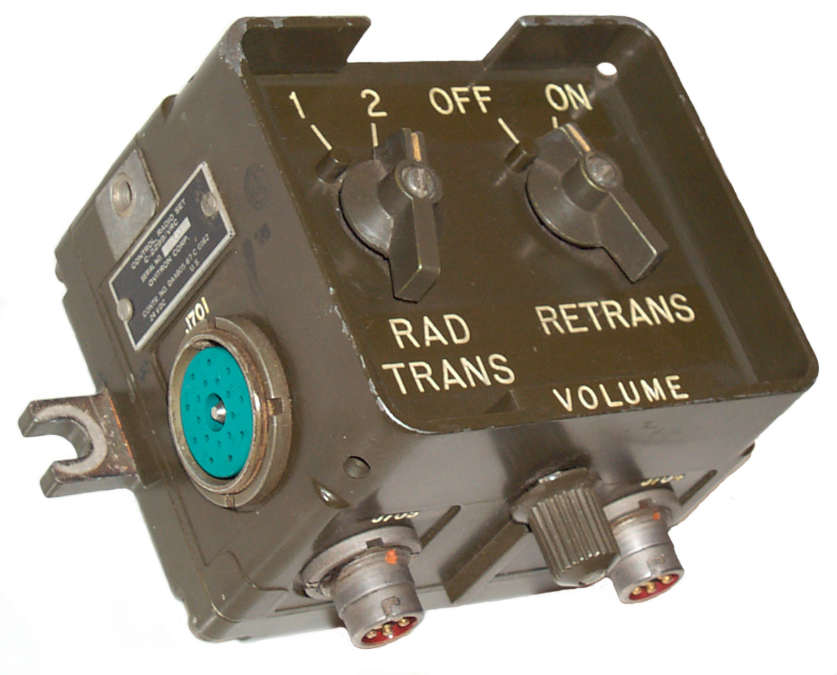
 One of the big
advantages of retransmission is that it allows cross band
communication. For example if a VRC-64/PRC-77
VHF low band radio is connected to a GRC-213
HF radio using the C-2299 Retransmission box. Then someone
within range of the VRC-64 can use a hand held PRC-126 radio to make simplex contacts
on HF radio.
One of the big
advantages of retransmission is that it allows cross band
communication. For example if a VRC-64/PRC-77
VHF low band radio is connected to a GRC-213
HF radio using the C-2299 Retransmission box. Then someone
within range of the VRC-64 can use a hand held PRC-126 radio to make simplex contacts
on HF radio. 


