SM-9312 Spectrum Monitor |
 SM-9312 Spectrum Monitor |
UHF Tuner SUT-1000C-1 |
 UHF Tuner SUT-1000C-1 |
VHF Tuner SVT-30C-1 |
VHF Tuner SVT-30C-1 |
LF Receiver S302-1 |
|
Control Panel Front |
 Control Panel Rear |
 REI CMP-700 Bug Detector |
CEI
SM-9312 Spectrum Monitor
UHF Tuner SUT-1000C-1
VHF Tuner SVT-30C-1
Control Panel
LF Receiver Type S302-1
Documentation
Patents
Bugs
Nonlinear Junction Detector
Research Electronics International CMP-700
NLJ Patents
NLJ References
SCIFs & Screen Rooms
Related
Links
Background
To learn what Tempest is see The Complete, Unofficial TEMPEST Information Page or do a Google search on Tempest (Wiki: TEMPEST, Van Eck phreaking, RINT, Markus Kuhn). Since the 1950s it has been known that it was possible to gather information by means of the electromagnetic emanations from some electrical device. An example is that early teletype machines using 20 or 60 ma current loop circuits to feed on line encryption equipment sent signals down the wire in addition to the encrypted information that would allow someone to read the plain text message directly (i.e. without even looking at the encrypted signal). There was a major U.S. project during the cold war where we tunneled under the West German border and tapped a trunk line to get these signals. This is described in the book Wilderness of Mirrors by David C. Martim, Ballantine Books as part of their Espionage/Intelligence Library 1981, ISBN 0-345-29636-2.
Other examples of Tempest attacks are using radio equipment in a van outside someone's office to see what is being displayed on their computer monitor. A newer way to do this is to use a telescope and photo multiplier tube to look at light reflected from the wall or ceiling that's coming from a CRT or LCD and reconstructing the image. Another modern tempest attack is based on looking at the modulation on the "power on" LED and recovering information. Or processing the signals from a cell phone that's near some encryption equipment.
Optical Time-Domain Eavesdropping Risks of CRT Displays by Markus Günther Kuhn.
TEMPEST is an acronym for "Telecommunications Electronics Material Protected from Emanating Spurious Transmissions"
CEI and WJ RS-111 receivers - the RS-111 receiver used by Nixon's Watergate team to listen to the bugs is in the same product family as these CEI receivers.
The NSA has recently (9-27-2007) declassified a paper "TEMPEST: A Signal Problem". Bell Labs discovered a problem with the SIGTOT 131-B mixer used to encrypt teletype messages.
These receivers were typically used in conjunction with a screen room (Wiki) and were used to look for radiated and using power line couplers conducted emissions coming from the equipment under test. The signals they were looking for would be strong and so these receivers are not at all good for using with an antenna to hear weak radio signals going over the air.
When looking for weak signals that are continuous wave (Wiki CW) the sensitivity of a receiver depends on how narrow the true bandwidth is. For example the HP 4395A when used as a spectrum analyzer has a true RMS bandwidth of 1 Hz. But for receiving modulated signals the receiver is most sensitive when it's demodulator is matched to the transmitted signal. For example the signal from GPS satellites is below thermal noise on the surface of the Earth, but a GPS receiver can take the wide band signal and pull it out of the noise.
CEI
Communications Electronics Inc. (CEI) later bought by Watkins Johnson (WJ) made a test system primarily designed for testing equipment that was to be certified as not having any emanations that could be used to recover any useful data.
From W-J Application Note 1307.50 "RS-125-17 Tempest Receiving System" Introduction:
"The Watkins-Johnson RS-125-17 TEMPEST Receiving System represents a highly versatile arrangement of equipment's designed primarily to meet the TEMPEST measurements requirements of NACSEM-5100. The system is also well suited for spectrum surveillance, electromagnetic surveys range monitoring, propagation studies, electromagnetic pulse (EMP), and analysis of electromagnetic emanations. The RS-125-17 is a manual wide band receiving system providing continuous coverage from 1 kHz to 1 GHz. The system is extendable on the high end of the tuning range for ultimate coverage to 18 GHz."
The mention of "manual" indicats to me that there was work on systems that were under computer control or they already existed.
The system consisted of 3 sloping face rack panels (holding maybe two dozen rack boxes like these) that were above table height with:
I think the equipment on this page with the CEI brand is slightly older than that used in the W-J RS-125-17 TEMPEST Receiving System. Both these CEI boxes and the W-J boxes shown in the app. note have almost identical appearance and function but with minor differences. Note that these CEI boxes use MC (Mega Cycles) and the WJ App note uses MHz (Mega Hertz).
- VLF Receiver and Converter
- HF, VHF and UHF tuners
- IF Demodulators
- Switching hardware
- Display and Monitor Hardware
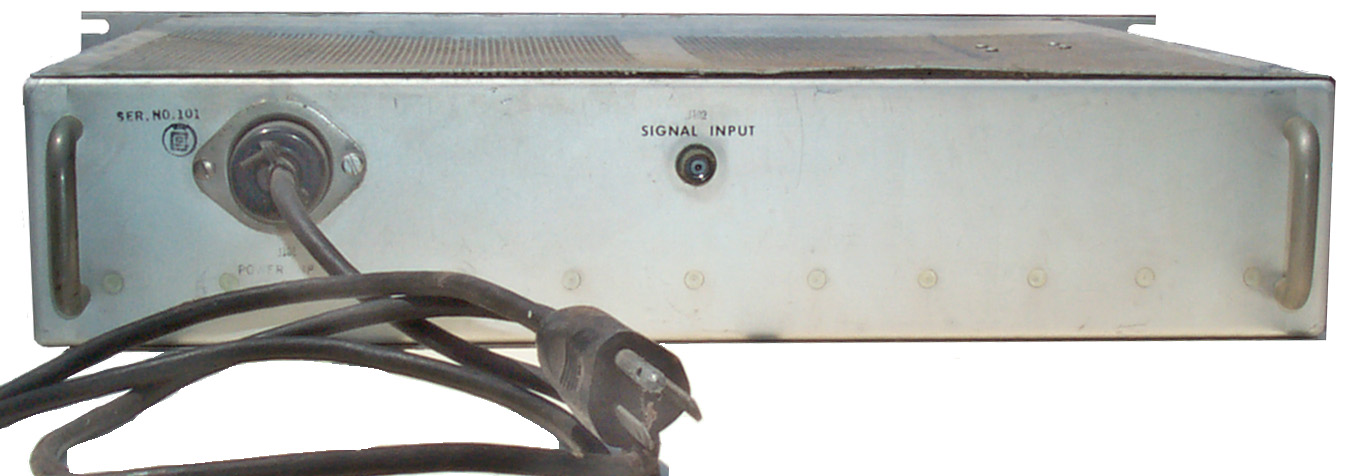
SM-9312 Spectrum Monitor
This 2 rack unit (3.5") high box takes in the 21.4 MHz IF outputs from the tuners and displays a frequency spectrum. If you know the frequency range the tuner is scanning you can recognize the modulation type. For example TV signals look different than FM radio is different form narrow band FM communications signals. Having a spectrum display makes finding signals much easier since you can see where there's activity.
In addition to using this Spectrum Monitor you can also feed the 21.4 MHz IF tuner outputs into a communications receiver that can then demodulate wide and/or narrow FM as is used in most VHF and UHF communications and for TV sound.
Golden age construction, i.e. transistors and mostly Nuvistors.
Controls
- Gain - When full CCW it takes a +8 dBm signal for full scale deflection, when max CW it takes a -100 dBm signal for full scale
- Sweep Width - the widest setting (CW) provides (left to right) 22.5 MHz to 20.5 MHz, at about 9 o'clock it's 21.51 to 21.64, and with fully CCW the top of the peak fills the screen.
- Center Freq - allows centering the frequency (different from horizontal position). The center of the range is a little off from 21.4 MHz, but I don't have a manual for this box that tells how to make the centering adjustment.
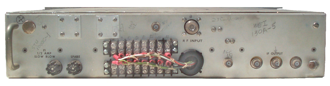
UHF Tuner SUT-1000C-1
There are two seperate tuners in this 2 rack unit (3.5") high box, one for 225 to 500 MC and another for 490 to 1000 MC. The SUT-1000B and SUT-1000C each have Slo-Syn motors so that either the front panel multiturn knob or the motor can tune the radio. The motors are designed to scan up and down between two limits. You might call this an early scanner radio. Some say real radios have motors.
The output is a signal at 21.4 MHz that is fed to the Spectrum Display and to Demodulator boxes (which I don't have).
Construction is "Golden Age", that is to say discrete components, transistors and Nuvistors (6CW4, 7077, 7486, 7587 in the front end) on printed circuit boards.
Instruction Manual for Type SUT-1000C Tuner is about 1/2" thick and includes alignment, maintenance, schematics, parts list and the remote modification information.
The front panel band switch was removed when I got these tuners. This was done as part of the motorization option so the the band selection could be remotly controlled from pin "P" (green wire) on the rear panel. Open is low band, -24 VDC for high band.
I replaced the 19 pin MS series connector with barrier strip screw terminals.
VHF Tuner SVT-30C-1
There are two seperate tuners in this 2 rack unit (3.5") high box, one for 30 to 60 MC and another for 54 to 260 MC. The B and C versions have Slo-Syn motors like the UHF tuner.
The output is a signal at 21.4 MHz that is fed to the Spectrum Display and to Demodulator boxes.
Instruction Manual for Type VT-30C Tuner (and SVT-30C Tuner) is about 1/2" thick and includes alignment, maintenance, schematics, parts list and the remote modification information.
Construction is "Golden Age", that is to say discrete components, transistors and Nuvistors ( 6CW4s and 7587s in the front end) on printed circuit boards.
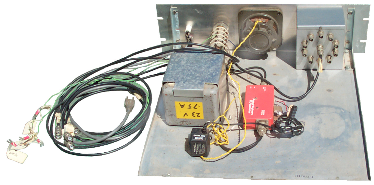
Control Panel
This is a 3 rack unit high (5.25") panel. Made mainly to control the CEI tuneers but also to do some other useful control functions.
The band switch also sends DC to the relays in the dual band tuners to select which band they operate on. It also routes the common output from the SP10T antenna switch to the correct Antenna input so the antenna is swithced to the band in use.
- On the left is a home brew SP10T coax switch that was used to allow multiple antennas to be routed to one of the instruments in this system.
- There is a military 600 Ohm speaker to provide a frount mount speaker
- I did not have the LF Receiver at the time I was using this system so included a Palmor Engineers low frequency converter to translate 10 kHz to 500 kHz up into the HF band. So the band switch has a the following positions:
- 10 kHz to 500 kHz
- 50 kHz to 30 MHz (feeds the DR-33C HF receiver)
- 30 to 62 MHz
- 54 to 260 MHz
- 225 to 500 MHz
- 490 to 1000 MHz
- The ON-OFF switch feeds both a wall wart to power the Palmor Engineers converter (instead of a 9 VOlt battery) and the DC supply to drive the band switching relays in the dual band tuners.
LF Receiver Type S302-1
This is a 2 rack unit (3.5") high receiver that has a single tuning knob and a single large Slo-Syn motor. There are three bands: 30 to 60 kC, 60 to 140 kC and 140 to 300 kC. There is a front panel 1/4" phone jack and rear panel audio out terminals. I have no manual for this receiver.
Terryo: Data Sheet -
Documentation
- W-J App. Note 1307.50 Dedcember 1975, RS-125-17 TEMPEST Receiving System, 20 pages
- CEI Instruction Manual for Type VT-30C Tuner (and SVT-30C), aprox 100 pages
- CEI Instruction Manual for Types UT-1000B and SUT-1000B Tuners, aprox 125 pages
- My hand drawn diagrams, about 26 pages
Patents
2513392 High-Frequency Tuner, Robert J. Aust (Mallory), Jul 4 1950
2513393 High-Frequency Tuner Device, Cleon F Fry & Robert J. Aust (Mallory), July 4 1950
2666906 Spiral Tuner, Robert J. Aust (Mallory), Jan 19 1954 - very close to the Inductuner
2787713 Television Tuner, Robert J. Aust, Cleon F Fry, Lawerence R. Goetz & Ned C. Skillman (Mallory), April 2 1957
10264440 Apparatus and method for rapid electronic device discovery, John Dishon, Joshua N. Edmison, John-Francis Mergen, Zachary Leuschner, Kerry Wood, Laurie Waisel, Richard BurneTyler Shake, Raytheon, 2019-04-16, - the Other Publications section has some interesting titles - seems to be a bug finder.
Bugs
While bugs are a different subject, they are related to TEMPEST.
YouTube: The Spying Game - "Walls Have Ears" (Complete)
5:57: The Thing (Wiki) passive cavity resonator
8:04: Using mikes that already are in the room
9:45: Berlin Cable Tap (in Wilderness of Mirrors, see Background above)
13:33: Transistor (Wiki) allow small battery powered RF bugs
18:39: Vietnam outdoor intrusion sensors: TRC-3, ADSID & PSR-1,
20:26: Sweeper (bug hunter) CryptoMuseum: Lee Tracey, "Scanlock", Audiotel,
22:09: Remote turn-on -> Broom Non Linear Junction detector, Charles Bovill,
- The Spying Game - "Spies in the Skies" (Complete) -
- Secrets of Spies Documentary on the Tricks Used by Spies -
Nonlinear Junction Detector
Wiki: excites the target area and looks for harmonics of the excitation signal.
The thing that makes this difficult is the excitation signal source may not be a pure signal, but rather contains some second and third harmonic distortion. These signals ideally would be nonexistent.
History: "By looking at the ratio between the 2nd and the 3rd harmonic of the base frequency, the operator can tell the difference between a semiconductor (i.e. an electronic part) and a natural structure."
Research Electronics International
CPM-700 Countersurveillance Probe/Monitor
2023Dec 5: I'm thinking that the CPM-700 is not using the two channel technology so is related to neither 5241699 nor 6397154, but rather is just a classical RF detector type bug detector. I has the capability of demodulating AM bugs, but will still detect FM bugs. The key factor in coming to that conclusion is that I have not found a provision for the second audio channel input. The Speaker can only be used as a speaker, not as a microphone. The Aux input is an alternative input that can not be used at the same time as the front panel BNC main input.
"CPM-700 Counter Surveillance Probe Bug Sweep Kit" is the eBay title. Some are offered with probes with clipped leads and others are just the main box.
These showed up on eBay 2023 Oct and have had wires and cables cut. I'm guessing the seller got them on the condition that they would not be sold in working condition.
from the manual (REI_CPM%20Manual.pdf):
The CPM-700 detects and locates transmitting devices, quickly and silently, including:
• AF (Audio Frequency)……...100 Hz to 15 kHz.
• VLF (Very Low Frequency)….15 kHz to 1 MHz an
• RF (Radio Frequency...……..50 kHz to 3 GHz
With the additional probes and accessories, the CPM can detect and locate:
• High Frequency transmitters (3 - 12 GHz, such as 802.11 wireless networks and 5.8 GHz cordless telephones, with BMP-1200)
• Infrared transmitters (with IRP-700)
• Magnetic Leakage (with MLP-700)
• Acoustic Leakage vulnerability (with ALP-700)
manual page 20: The CPM-700 is primarily sensitive to amplitude information.
manual page 20 & 21: A note concerning power: Surveillance RF transmitters can be divided into four power groups: micro power, low power, medium power, and high power. Transmitting distance is dependent not solely on power but also antenna placement and design, structural environment, ambient noise, and the receiver and its antenna.
Power
- High power bugs generally, though, can broadcast a quarter mile or more with >= 100 milliwatts.
- Medium power devices use 1 to 100 milliwatts for a distance of 300 feet to a quarter mile.
- Low power bugs transmit less than 300 feet, using less than 1 milliwatt.
- A separate breed of transmitters, called “micro power bugs” is designed to be undetectable with a power of one microwatt or less.
8 AA batteries, either Alkaline or Ni-MH/Ni-Cad. (8 * 1.5 = 12V, 8* 1.2V = 9.6V)
eBay Title:"12V 1A AC/DC Switching Power Supply Charger Adapter 5.5mm 2.1mm 100-240V"
The Battery pack and External DC input are combined with a diode OR so the highest voltage source will power the CPM-700.
The Probe input has a DC output to power active probes.
The first wall wart I got was labeled: AC adapter: 12 VDC <= 500 mA, 5.5 x 2.0 Power Plug, center positive. 2023Nov27: have on order with 5.5x2.1 power plug <$5 eBay free shipping. The output measures 12.4 VDC with no load. This is less than the 13.03 VDC open circuit, or 12.63 VDC when the CMP-700 is powered on. That means the diode OR function will not work properly. For that to work the external DC voltage needs to be greater than the battery voltage. But this will work very well when the battery pack is not being used.
Second try 2023Dec8: eBay title: Gemini Audio AC-DC Wall Type Plug-In Power Adapter
Model: No.: DC120300
Input: 120 VAC 60 Hz 8W
Output: 12VDC 300mA
2.1x5.5mm positive center
in the text it says "unregulated" so the open circuit voltage should be a few volts higher than 12. The problem with higher input voltages is the power dissipated in the LM2931 linear voltage regulator.
Probes & Accessories
Factory probe coax is RG-122/U.
The BNCm Input connector has +6.5 VDC on the center conductor in both Monitor and Search modes to power active probes.
Model
Photo
Description
DMM
Ohms
Diode V
Standard RF Probe
short whip antenna and low noise amplifier (50 kHz - 3 GHz), 20 dB gain.
Do not exceed 50 VDC or +15 dBm.
360
0.360 V
VLF Probe
has the look of a wall wart but has a BNCm cable connector, so a circuit that blocks the line voltage but passes VLF
15 kHz to 1 MHz
Do not exceed 300 VAC 50-60 Hz, +15 dBm >5 kHz
TVLF Adapter
2-prong AC socket to fit VLF probe and Alligator clips illustrated connecting to a 66 block.
Auxiliary Input Amplifier
a cable that connects a pair of alligator clips to the Aux audio Input on the side of the CPM-700
BMP-1200
Broadband Microwave Probe - fan shaped probe - (2 - 12 GHz)
Green LED: no attenuation, Yellow LED: 20 dB attenuation.
The LED is inside a button which can be pressed to toggle the attenuator.
not sure how it works
RF "Sniffer" Probe
cylinder maybe 5/8" dia x 3" - not sure how it works
10 MHz to 3 GHz, Gain: 20 dB nominal,
336
0.337 VIRP-700
Infrared Probe - cylinder like the Sniffer
10 kHz to 5 MHz, 725 - 1150 nm (near IR), gain 40 dB
5k8
0.777/0.597 V
MLP-700
Magnetic Leakage Probe - cylinder longer than the above
Center 40 kHz, Usable 20 to 250 kHz, gain: 40 dB
438k/5k
0.766/0.596 V
MPA
Modular Phone Adapter - This is a commercial breakout device that gives access to the terminals
ALP-700
Acoustic Leakage Probe - a microphone, maybe contact type?
Connects to the side panel 1/4" Aux Input phone jack, not the BNCm front panel input.
50 Hz to 10 kHz, 47 kOhm unbalanced.
NCB
8 AA Ni-Cad battery pack (also Ni-MH battery back, or loose rechargable cells in battery holder.
CLA
Cigarette Lighter adapter for automotive use.
Aux Audio In
Do not exceed: 50 VDC, 150 VAC@30 Hz (i.e. OK for direct connection to phone line)
As Received
There is something loose inside the CMP-700 that makes noise and the cables have been cut on all the probes. I've ordered some 15' RG-174/U cables with BNCm connectors on each end that will be cut in half to supply the cables. The heatsink for the LM2931 voltage regulator has come loose.
Caution required when removing bottom cover since piezo (2.8 kHz) plastic case and PCB may be glued to bottom cover and are tight fit into PCB.
After stabilizing the piezo buzzer using Kapton tape (Wiki) to hold the piezo PCB and Silicon RTV to hold the case to the main PCB and reconnecting the heat sink to the LM2931CT voltage regulator the unit was dead when powered up. The problem seems to be a dead LM2931. There is zero volts on the output pin. That might have happened because of the loss of the heat sink caused over heating or more likely because the screw, nut or lock washer that were loose inside shorted out the power supply. 2023 Nov 20 have 10 each LM2931CT on order. This is probably why this unit was put on the surplus market. That's to say there are more modern bug detectors so it may not have made sense to pay for a factory repair.
What's What
In order to locate a bug with the CMP-700 some source of audio needs to be provided. That gives the bug something to transmit and something to hear in the headphones. Maybe a tape of people talking or of music or of noise or traffic, &Etc.
There are two REI patents that may describe the CMP-700. One depends on phase correlations and the other depends on time delay correlations. Both use the loudspeaker as a microphone in the Search mode that supplies one of the correlation channels.The wideband RF receiver supplies the other channel.
The piezo device provides a loud beep when the alarm threshold has been exceeded. Note it is connected to a power supply, i.e. it is not working as a microphone.
Since the loudspeaker is acting as a microphone in search mode it's position relative the the bug is important. Because of this the main CMP-700 box should be moved around the area being searched for bugs. The strongest indication will come when the CMP-700 speaker is near the bug's microphone.
The speaker functions as a loudspeaker and not as a microphone.
Integrated Circuits
Near BNC input: TDA2320A, LT1006, LM324N, ST HCF 4066B
behind Gain knob: ST HCF 44020B, ST HCF 44081B, F CD4049, ST HCF 44066B, ST MC3403N
at back: LM380N, LM2931, adjustment post for Low Battery Voltage & Voltage Regulator putput
Qty
Model
Description
Vmax
1
TDA2320A Dual IR preamp
20
1
LT1006 Precision Op Amp
22
1
LM324N 1 MHz Op Amp
32
2
ST HCF 4066B Quad Switch
22
1
ST HCF 4020B 14 stage counter
22
1
ST HCF 4081B Quad 2-input AND gate
22
1
F CD4049 6 Chan 3V to 18V Inverter
20
1
ST MC3403N Quad Op Amp
18
1
LM380N 2.5 Watt Audio Amp
22
1
LM2931 LDO adj analog V Reg
40
Other Parts
REI SH-400 Low Leakage Headphones
Photos
Fig 1 Probes left to right:

- Standard RF Probe w/ telescoping whip.
- MLP-700 Magnetic Leakage Probe
- IRP-700 Infrared Probe
- RF "Sniffer" Probe
Fig 4 Piezo buzzer uses 3-wire system with active circuit that resonates at it's natural frequency, the small PCB has a couple of transistors. LM29321 nut jammed near front panel.
See Mallory Sonalert (Stack Exchange) and scroll down to Self-Drive Transducer Circuits. Note the small finger contact goes to the transistor base or gate input. The idea is that the oscillator runs at the self resonant frequency of the particular piezo element and therefore is the loudest frequency.
Murata: 7BB-35-3C (35mm dia), 7SB-34R7-3C (34mm dia) both to be discontinued in 2024. The 3 terminal piezo disks now (2023) seem hard to find. The only ones on eBay (Nov 2023) are the 50mm dia 35W ultrasonic cleaner type for about $12 each.
Fig 1
Fig 2
Fig 3 LM2931 (lm2931-d.pdf) heat sink loose.
Lockwasher stuck to speaker magnet.
Round black plastic under speaker is piezo assembly.
Fig 4 Found nut for LM2931 near front panel.
Piezo PCB glued to bottom cover makes it tricky
to remove bottom cover (poor design).
Fig 5 Input circuit with bias output and diode limiting.
Fig 6 LM2931 with heat sink connected.
Note Silicon RTV on Piezo case.
Fig 7 Piezo buzzer with Kapton Tape (Wiki)
holding PCB. Note vertical position.
Fig 8 Replacing the LM2931 fixed it, now working.
The speaker makes noise when in Monitor mode.
Fig 9 Battery holder 8 AA working with Alkaline cells.
South Co Fast Lead fastener?
(12-11-404-11? - 12-12-305-11?)
Fig 10 Using BMP-1200 Probe
The probe LED stays Yellow (20 dB atten)
all the time.
Fig 11 The fastener is NOT a 12-11-404-11 Fast Lead.
Fig 12 2nd try at External Power Supply
Fig 13 2nd try at External Power Supply
References
White Collar TV series; S1:E9 "Bad Judgement" (IMDB, Wiki) -
White Collar 1x09 "Bad Judgement" Sneak Peek #1 | Find that bug, 1:35 - using standard RF probe after fully extending the antenna.
CPM-700 Patent Search
None found that makes sense for the CPM-700.
5020137 Case-mounted receiver with antenna, Bruce R. Barsumian, Research Electronics International,1991-05-28, - about suitcase packaging of antenna for OSCOR
5241699 Electronic surveillance device detector and method using phase angle differences between two received signals, Bruce R. Barsumian, Research Electronics International, 1995-09-18, - see OSCOR below.
comment in patent 6397154: "This method relies on a phase correlator. The main drawback of a phase correlator is that it does not consider the phase distortions and time delays that result from the Speed of Sound and echoes from within the environment. Furthermore, it has the drawback that the phase correlator works very well for a continuous audio tone with a constant phase, but works poorly if the audio source has a very wide bandwidth with little continuous tone content."
cites EXAR XR-2228 Monolithic Multiplier/Detector used in PLL circuits. (Vmax: 18)
Cites:
4218592 Telephone analyzer for detection of clandestine devices, Arvey Z. Steinbergs, Ray H. Taylor, James T. Whalen, GD Govt Sys (GTE Products), App: 1967-03-14, Vietnam, Korea, Pub: 1980-08-19, - references Electronic Design, June 21, 1966 "The eavesdroppers: ‘Fallout’ from R&D" about the The Thing (Wiki). But I don't think that's what this is testing, rather it's looking for telephones that have the mike connected when on-hook.
4658099 Apparatus and method for remotely determining the presence of unauthorized surveillance devices on a communications line, Byron T. Frazer, Security Call Inc, 1987-04-14, -
4797635 Tracking loop having nonlinear amplitude filter, G. Stephen Hatcher, Boeing, 1989-01-10, - used in relation to a phase detector
5034963 Apparatus for visually aiding MSK detection and interference recognition and classification, Paul A. Singer, Navy, 1991-07-23, - scope for tuning RTTY receivers where phase is important.
Cited by:
6021269 Radiation (bug) source detection by recording spectral records at different times or locations and collating the spectral records, Lewis; Owen Melfyn, 2000-02-01, -
6397154 Correlation method for surveillance device detection, Thomas H. Jones, Bruce R. Barsumian, Research Electronics International, 2002-05-28, - compares room audio to audio from intercept receiver using correlators that allow for time delays
Cites:
Publication P date Pub date Assignee TitleDE2428299 11974-06-12 1976-01-02 Waechtler Maximilian Dr Detector for bugging senders - signals directly collected by microphone are correlated with demodulated LF signal from receiverUS5241699 1990-09-10 1993-08-31 Barsumian Bruce REl ectronic surveillance device detector and method using phase angle differences between two received signalsUS5416844 1992-03-04 1995-05-16 Nissan Motor Co., Ltd. Apparatus for reducing noise in space applicable to vehicle passenger compartmentUS5426703 1991-06-28 1995-06-20 Nissan Motor Co., Ltd. Active noise eliminating systemUS5717656 1996-08-20 1998-02-10 Ybm Technologies, Inc. Method and apparatus for detecting and locating a concealed listening deviceUS5910993 996-05-16 1999-06-08 Nissan Motor Co., Ltd. Apparatus and method for actively reducing vibration and/or noiseUS5956318 1996-01-29 1999-09-21 Samsung Electronics Co., Ltd. Orthogonal frequency division multiplexingUS6018689 1996-11-08 2000-01-25 Nissan Motor Co., Ltd. Active vibration reducing apparatus and method for identifying transfer function in active vibration reducing apparatus
Cited by:
Pub P date Pub date Assignee TitleWO2004038455 2002-10-22 2004-05-06 Audiotel International Limited Method and apparatus for detecting surveillance devicesUS6754488 2002-03-01 2004-06-22 Networks Associates Technologies, Inc. System and method for detecting and locating access points in a wireless networkGB2406915 2003-10-10 2005-04-13 Agilent Technologies Inc Signal correlation in the frequency domain.US20050104731 2003-11-17 2005-05-19 Woojoo It Co., Ltd. System and method for detecting eavesdropping deviceUS20050222844 2004-04-01 2005-10-06 Hideya Kawahara Method and apparatus for generating spatialized audio from non-three-dimensionally aware applicationsUS20060207781 2005-03-07 2006-09-21 Denier Electric Co., Inc. Electrical box extenderUS20060250299 2003-05-21 2006-11-09 Falk Kent O Method and system for unambiguous angle resolution of a sparse wide-band antenna arrayGB2429316 2005-08-16 2007-02-21 Vodafone Plc Modulating an unobtrusive sound wave with dataUS7385515 2005-06-02 2008-06-10 Owen William K Surveillance detection system and methods for detecting surveillance of an individualGB2447311 2007-03-08 2008-09-10 Dennis Huang Acoustic generator and radio signal decoder for detecting a hidden bugUS7852259 2004-01-23 2010-12-14 Telefonaktiebolaget Lm Ericsson (Publ) Clutter filteringUS20130135526 2011-11-30 2013-05-30 Kabushiki Kaisha Toshiba Electronic device and audio output methodUS20140226014 2008-12-11 2014-08-14 At&T Intellectual Property I, L.P. Method and apparatus for vehicle surveillance service in municipal environmentsUS20150070146 2013-09-06 2015-03-12 Immersion Corporation Systems and Methods for Generating Haptic Effects Associated With Transitions in Audio SignalsUS9619980 2013-09-06 2017-04-11 Immersion Corporation Systems and methods for generating haptic effects associated with audio signalsUS9934660 2013-09-06 2018-04-03 Immersion Corporation Systems and methods for generating haptic effects associated with an envelope in audio signalsRU2707418 2018-09-11 2019-11-26 Валентин Михайлович Шурубура Device for protection of information from leakage through channels of secondary electromagnetic radiations and interference caused by computer equipmentWO2021094255 2019-11-14 2021-05-20 Sony Corporation Communication device and method for secure communication20050104731 System and method for detecting eavesdropping device, Woojoo It Co,
GB2408864 Integrated search head for counter surveillance equipment, Audiotel International, - looks like metal detector
20080072331 Protecting secret data entry from infrared and audio eavesdropping, IBM, - using thermal signature to read key pad.
GB2447311 Acoustic generator and radio signal decoder for detecting a hidden bug, Dennis Huang - matches received audio to audio generated by bug detector.
OSCOR Omni Spectral Correlator Patents
4399556 Device for locating audio surveillance apparatus, Glenn H. Whidden, 1983-08-16, -
Cites:5020137 Case-mounted receiver with antenna, Bruce R. Barsumian, Research Electronics International, 1991-05-28, - active antennas mounted in briefcase lid.
3473127 Covert transmitter detector, Richard E Williams, John S Gerig, Scope Inc, 1969-10-14, - cigarette pack size Rx uses comb generator to get audio output without tuning RF front end.
3939420 Debugging arrangement, Sture Risberg, Alf Lindgren, Kjell Rixon, Rickard Wallden, Bengt Brundin, 1976-02-17, - Floods room audio tone at known frequency and looks for it after detection (AM/FM).
4127817 Transmitter detecting apparatus, Allan D. Bell, Jr., Dektor Counterintelligence and Security, 1978-11-28, - RF amp feeds a diode detector. i.e. a Crystal-Audio receiver. See RWR.
4264978 Device for locating audio surveillance apparatus, Glenn H. Whidden, YKK Corp, 1981-04-28, - floods room with audio pulse and time of arrival gives range to bug.
4368539 Transmitter detector, Glenn H. Whidden, 1983-01-11, - Spectrum scan where prior scan is subtracted from current scan to find new signal (bug).
5241699 Electronic surveillance device detector and method using phase angle differences between two received signals (see above) -
Orion Non-Linear Junction Evaluator
Probably made under license from REI. Sticker price $17.5k
5815122 Slot spiral antenna with integrated balun and feed, Michael W. Nurnberger, John L. Volakis, University of Michigan, 1998-09-29, - cites 23;
6057765 Non-linear junction detector, Thomas H. JonesBruce R. Barsumian, Research Electronics International, 2000-05-02, - has the look and feel of a metal detector with telescoping probe.
6163259 Pulse transmitting non-linear junction detector, Bruce R. Barsumian, Thomas H. Jones, Research Electronics International,2000-12-19, - Tx 900 MHx, Rx @ 1800 & 2700 MHz. has the look and feel of a metal detector with telescoping probe.NLJ Patents
2773253 Method of detecting discontinuities in the reflective properties of surfaces, David E Sunstein, Space Systems Loral (Philco Ford), 1956-12-04, - RADAR set with added discriminator in receiver
3518546 Harmonic communication and navigation system, Harry A Augenblick, John G Vogler, Microlab FXR, 1970-06-30, -
3631484 Harmonic detection system, Harry A Augenblick, Microlab FXR, 1971-12-28, -
3798642 Recognition system, H Augenblick, W Engle, Microlab FXR, 1974-03-19, - uses multiple tank circuits to control reflected harmonics.
4053891 Radar object detector using non-linearities, Charles L. Opitz, Lockheed, 1977-10-11, - RADAR that looks for harmonics rather than the fundamental.
5191343 Radar target signature detector, Paul M. Danzer, Michael J. Brienza, Norden Systems, 1993-03-02, - RADAR uses two transmitters to look for nonlinear aspects of the target.
6057765 Non-linear junction detector, Thomas H. Jones, Bruce R. Barsumian, Research Electronics International, 2000-05-02, - has the look and feel of a metal detector with telescoping probe.
6897777 Non-linear junction detector, Steven John Holmes, Andrew Barry Stephen, Audiotel International, 2005-05-24, -
20040095243 Non-linear junction detector, Steven Holmes, Andrew Stephen, Audiotel International, 2005-05-24, - about controlling drive power level to improve sensitivity.


9209856 Spread spectrum non-linear junction detector, Bruce R. Barsumian, Thomas H. Jones, Darrell L. Harmon, Research Electronics International, 2015-12-08, - REI NLJD - 900 mHz or 2.4GHz excitation frequency, look and feel of a metal detector with displays on back of search coil.
NLJ References
Crypto Museum: Charles Bovill, (S-Phone, Scanlock Broom ECM, Rebecca/Eureka (Wiki)) TSCM\NLJD,
GBPRR Non-Linear Junction Detector - DIY + information on commercial units. - DIY Projects: GPS Jammer, Cell Bug, Trunked radio jammer, Laser Warning Receiver, Night Vision Jammer, & many more. STANAG 3733: Laser Pulse Repetition Frequencies Used for Target Designation and Weapons Guidance
Martin L. Kaiser: Nostalgia - FBI Vendetta Against Martin Luther Kaiser III - Manufacturer of Bomb Detection and Disposal Equipment specializing in Improvised Explosive Device (IED) Detection -
SCIFs & Screen Rooms
A SCIF (Wiki) is a space that needs to meet several requirements that are aimed at stopping an adversary from learning what's going on in the room. This would include TEMPEST as well as acoustic and probably other types of shielding.
While working at Aertech we had a screen room that came broken down and was assembled where we wanted it. It was solid metal and about 8 to 10 feet on a side.
Not a place to be if you're claustrophobic. I think there were fancy power line filters so that we could use line powered test equipment in the room.
TRW, who purchased Aertech, had many SCIFs built into their buildings and for some programs we would meet in them. The door might be like used on a bank vault including high quality locks. But these were much larger than the small shielded room at Aertech so were not as claustrophobic, but the lack of a window was noticeable and once the door closes you know the room is sealed.
---- RF Only-----
2674644 Shielding and sealing gasket for electronic equipment, Alfred M Goodloe, Metal Textiles Corp, 1954-04-06, - for a few decades prior they made kitchen scouring pads. This is the same woven material they used to make high power resistors. They also make flame barriers as used on airplanes and in miner's lamps.
2765362 Screen rooms, Erik A Lindgren, 1956-10-02, - 10 to 43 MHz with >120 dB attenuation (common screen rooms of that time were more like 40 - 50 dB)
2853541 Door for screen room, Erik A Lindgren, 1958-09-23, - these were rooms made of metal window screen mesh attached to a wood frame. RF shielding only for some frequencies.
3009984 Door for a shielded enclosure, Erik A Lindgren, 1961-11-21, - Rf only
----- RF & Accoustic ----
4794206 RF shielded and acoustic room, Jonathan Weinstein, Industrial Acoustics Co, 1988-12-27, - SCIF - web page -
Related
4395 - In the Spectrum Analyzer mode covers 0 to 500 MHz with a true 1 Hz Resolution Bandwidth, so extremely sensitive.
Agilent E4404B ESA-E 9kHz - 6.7 GHz Spectrum Analyzer - Portable and can run on 12 VDC or 120 VAC.
Cell Phones -
Cryptography & Cryotographic Machines & Cryptographic Patents
FasTrak Vehicle ID Transponder - is an active transponder, not an RF ID tag.
Gamewell - Pen Registers (Wiki) - these were used to capture outgoing phone call numbers in the time of dial phones.
HP 71100A 2.9 GHz Spectrum Analyzer - a modular system
Key, Object & Pet Location Tags - the Apple tag is a real problem
Orion Electronics Ltd. Cellular Base Station ST616-CBS - fake cell tower to intercept cell calls
Phones
Probability of Intercept -
RF-204 RFI Detector - detects RF around 26 MHz, so not a general purpose bug detector
Shielding Integrity Monitoring System II RP98G & RP98D - to test RF integrity of shielding, like for SCIFs
Spying on Cell (Mobil) Phones -
Telephone Patents
Telephone Poles & what's on them
Links
Security Engineering - The Book - very practical info on why things fail
Communications Electronics Inc. and Watkins Johnson Radio Information Site - CEI Receivers -
NACSIM 5000 TEMPEST FUNDAMENTALS (U) -
TEMPEST 101 -
WJ - History and information on one of America's finest surveillance receiver manufacturers -
Wikipedia - Tempest
Jerry Proc's page Tempest
Terryo: WJ-CEI - Black Radios -
page created 16 May 2003.