Wild Heerbrugg
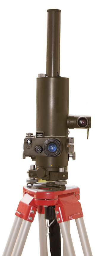
ARK 21 Gyro Aiming Circle
© Brooke Clarke 2015 - 2022Photos
GKK3 Power Supply
Related
References
Links
Background
This was from eBay where the item title was the same as my page title. But it turns out that while the item pictured in the eBay auction is the ARK 2 the item delivered to me is the ARK 1.
Got this instrument because of my interest in surveying and gyroscopic North finding. This is only the case and gyroscope, the inverter that supplies the 115 VAC 400 Hz 3-phase power and it's battery are so far missing (Fig 11),
Description
This Gyrotheodolite (Wiki) depends on the behavior of a pendulous gyroscope that will tend to align it's spin axis with the spin axis of the Earth, thus pointing to true North, not magnetic North. In order to do this the instrument needs to be setup close to pointing to true North. To facilitate that there's a build in magnetic compass designed to be accurate while the gyroscope motor is running (may be a slight error when no power is applied).
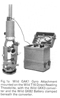
The Wild Heerburgg GAK 1 Gyro theodolite Attachment uses the same gyroscope but instead of having a built-in surveying telescope like this ARK 1 instrument, the GAK 1 must be mounted on top of a Wild theodolite.
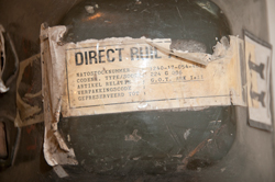
The shipping container has a label:
NSN: 1240-17-054-4883
G.O.T. ARK I+II
So this might have come from Germany. No Google hits on the NSN. Not sure of the meaning of ARK I+II. I now think this is the carry case that will work for either the ARK I or the ARK II.
MIL (Wiki) angle measure
The circles are graduated in NATO MILs not degrees. This is the unit used in artillery to measure angles because one mil is about 1 yard at a range of 1,000 yards (or 1 meter at 1,000 meters). There are 6400 mils in a circle. It's an approximation to a milliradian which would be to divide a circle into 1000 * (2 * PI) divisions or 6,283.185307... divisions. Rounded up to 6400 makes the small angle approximation that the SIN of an angle is the same as the angle when measured in radians (Wiki).
Lights
There are 3 lights (12V 2W bulbs) built-in. These need to be powered in order to see the various scales.
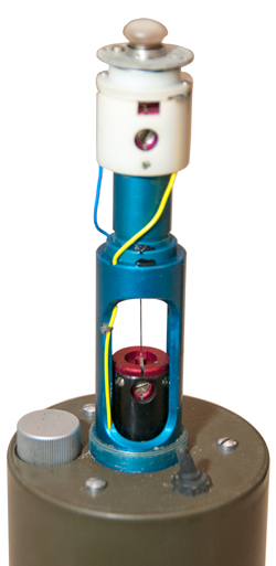
The target lamp (Fig 10) at the very top is controlled by the toggle switch, so only needs to be turned on at night when someone else needs to sight this instrument.
The Gyro circle is always illuminated by the lamp next to the toggle switch.
The horizontal circle is always illuminated by the lamp in front of the gun sight.
Controls
Fig 11E
Top of this page. Surveyor's view.
Gyro circle lamp cover (cap) just to the left of the tagret illumination toggle switch.
Gyro circle viewing magnifiers on tube at right (dust cap opened and hanging down). This tube can be rotated so that the lens now pointing at the surveyor can be pointed at the sky, forward, at the ground, &Etc. There's a half silvered mirror in the light path. Not sure why the two lenses.
The 3 eyepieces are grouped toghther. On the left is the magnetic compass sight. Just above it is a mechanical gun sight and between the front and rear sights is a button that frees the magnetic compass needle. In the center is the microscope to read the horizontal circle. Directly above this microscope eyepiece is the striding (cross) bubble level that can be used to plumb the instrument on the tripod. On the right is the large main telescope eyepiece with a focus adjustment for the reticle.
The large knob on the right controls the caging of the gyro (see Fig 5 description below).
There are knobs on both the left and right that are the fine azimuth control knobs that have limited range. Only the knob on the right has the ability to free the instrument for unlimited azimuth movement.
Fig 5
Target illumination toggle switch
VAST (Caged), VRU (damped) or OEMPEN (Free or open) - 3 position caging control knob
Vertical elevation control knob (angle readout on opposite side (Fig 7). Range +800 mills (=45 deg) to -200mills (-11 deg).
That's too bad because it pervents looking directly at the North star.
There is a black spring loaded lever behind the azimuth knob that allows moving the instrument in small steps
Fig 7
Power Socket
At the bottom left is the cap covering the power socket shown with the cap off in Fig 9.
Cap marked: Cannon MC 10-60.
Connector to make power cable: ITT Cannon MC11E-10-6SN
Pins marked A through F.
Guessing 2 pins for lamp power, 3 pins for motor, one pin spare or ground.
The power requirement is 115 VAC, 400 Hz, 3-Phase.
See the KGS Electronics SPC-6-1000-3PH 50/60Hz to 400Hz 3-Phase Frequency Changer web page for the power supply I plan to use.
Not sure what a phasing reversal will do. Probably nothing or maybe there will be a 180 degree azimuth error?
Also a 12 VDC input for the lamps. So: 3 wires for AC, 2 wires for DC and chassis ground?
Pin
Function
A
3-Phase
B
3-Phase C
3-Phase D & E
DC Ground F
+12 Lamps (adjustable)
The azimuth circle lamp cover is on the back side of the eyepiece block.
The telescope vertical angle readout is on the left.
Note Pin-D is connected to pin-E inside the gyro unit. If the cable is unplugged the opening of the D to E path will turn off the GKK3 power supply.
Photos
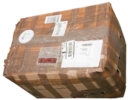
Fig 1 Box has loose contents and is bulged.
Fig 2 Inside box is loose, lack of packing and
carry case is loose in inner box. Poor packing.

Fig 3 Carry case w/shoulder straps.
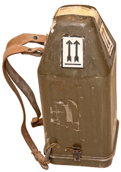
Fig 4 label on top of carry case
I think this label applies to the carry case, not it's contents.
NSN: 1240-17-054-4883
G.O.T. ARK I+II
Fig 5
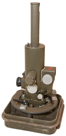
Fig 6
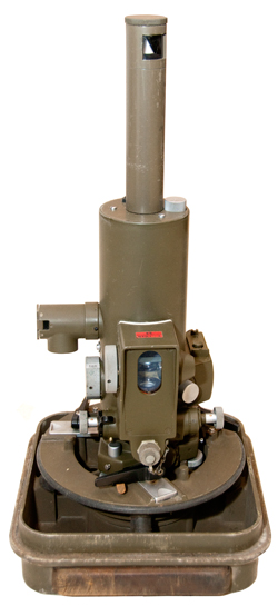
Fig 7
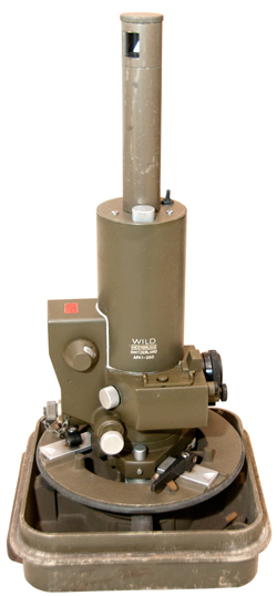
Fig 8
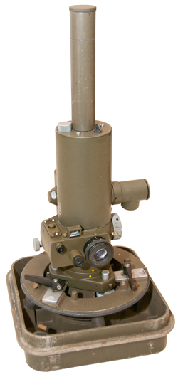
Fig 9 Power Connector

Fig 10 Lamp to illuminate target at night
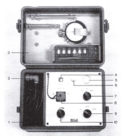
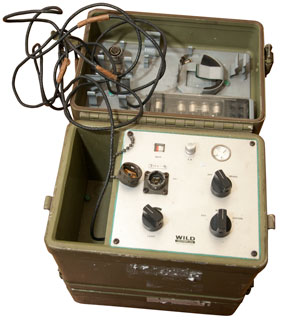
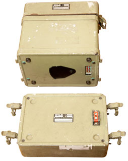
Fig 11 GKK3 Inverter Power Supply
1. Compartment w/ Gyro cable
2. Connector for Gyro
3. Lid with spare parts
4. Battery Voltage Meter
5. Gyro Speed Flag
6. 5Amp Fuse
7. Off-Run-Brake switch
8. 12V Input Connector PTO2E 12-3P
9. Off - Internal - External power switch
10. Gyro Light Brightness adjustment
Fig 12 On 5/8" tripod as seen by surveyor
GKK3 Power Supply
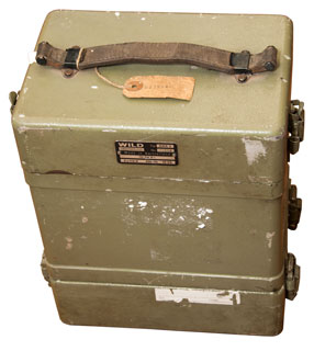
Arrived 23 May 2018 - took three years to find one. Took 15 days from Peru, packaging was lacking but it got here. Note white styrofoam that's crushed into paper thin sheets sticking to it.
This is a power supply that supplies the 3-phase 400 Hz power for spinning the gyroscope and also supplies 12 VDC (?) for the lamps. There are two possible sources of input DC for the power supply:
1. An internal battery
2. External 12 VDC source, like a car battery.
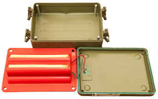
Battery Box GKB2
Outside dimensions:
Marked:
12 V 6 AH
Inside dimensions: (Fig 35) 7-3/8" x 4-3/4" inside posts, Bottom is 2-1/4" deep & cover is 5/8" deep = 2-7/8" total
Battery Pack Options
2*5 D Cells
Ready made battery pack: Battery Space: SL-DD10R2WR: 2x5 Side by Side = 10 ea D cells (12V 5AH) , $71.04 w/ CA tax & Shipping
This is slightly lower capacity in much smaller and lighter form.
This battery pack is: 6.3 x 2.6 x2.4" so will fit10 Each F Cells
To rebuild the battery pack 10 each "F" cells needed. NiCd Rechargeable Cell: 1.2V 7000 mAh F size Battery Flat Top (1 Pc) - $100 just for the cells
1.3" dia x 3.5" tall. The red plastic cell housing is 7-1/4" long on the outside, so easily 7" long for the two "F" cells. These are rated 7 AH, more than the factory rating. Requires rebuilding the existing battery pack.
10 Each D Cells
NiCd Rechargeable Cell: 1.2V 5Ah D Size Battery with Flat Top (1PC) - $61 ($82 after CA tax & shipping) Requires assembling a pack
Battery Charging
This does not seem to be mentioned. I'm guessing an external battery charger is needed? Maybe when an external 24 Volt power supply is connected (not the optional 12 Volt supply which requires an internal jumper) it might charge the battery?
Photos
Related
DC PM Motors - Testing DC Motors
Flywheels
Gyroscopes
North finding - Videos
surveying
theodolite
References
Links
PRC68, Alphanumeric Index of Web pages, Contact, Products for Sale
Page created 15 Sep 2015
