Connectors for Military Electronics
© Brooke Clarke 2001 - 2024
Background
Audio
Antenna
Battery
Contact Pins
Circular Multi-Pin
Rectangular Multi-Pin
Coaxial
Telegraph era
USB
Connectors:
A, B, Mini-B, Micro-B, C, USB3 Micro-B
USB-A to Multi Phone Charging Cables
Power
Delivery
HDMI
0.1" Headers
Unknown - Wanted
Links
Background
The first thing that you need after acquiring a military electronics
treasure is the power cord or some other cable. These are
almost never available so the next thing is to make up one, but that
requires the manual (see an example of reverse engineering) and the mating
connector.
Audio
Separate web page for Audio
connectors.
My main source for the U-183 (6 pin version of the U-229) has been
surplus cables sold on eBay. But they are available from Newark.
Antenna
Many field radios use what amounts to a threaded hole to
mount the antenna. In order to connect a coaxial cable you
will need some type of adapter.
PRC-68 series radio antenna adapter.
Contact Pins
The contact pins have a size number
that may be related to the American Wire Gauge (Wiki:
AWG)
of a solid copper wire. Connector makers have tables saying
what size wire can be used with a certain contact size, but those
are for solid wire. As the number of strands increases (for
the same total AWG) the bundle diameter increases. Also if
the wire is twisted the size gets bigger. So if you are
having trouble getting the wire to fit into a solder cup, first be
sure the wires are straight and second use a pin vise and drill
bit to slightly enlarge the hole. Note that it's common for
a bur to be pointing into the solder cup and just cleaning the bur
can make the difference.
Contact
#
|
Wires
AWG
|
Solid
Cu
Wire dia mils
|
Wire
Max
Amps
|
contact
Max
Amps1
|
22D
|
22 - 28
|
25.3 |
5.0
|
5
|
22M
|
24 - 28
|
25.3 |
5.0
|
3
|
22
|
22 - 26
|
25.3
|
5.0
|
5
|
20
|
20 - 24
|
32.0
|
7.5
|
7.5
|
16
|
16 - 20
|
50.8
|
13
|
13
|
12
|
12 - 14
|
80.8
|
23
|
23
|
8
|
8 - 10
|
128.5
|
46
|
46
|
4
|
4 - 6
|
204.3
|
80
|
80
|
0
|
0 - 2
|
324.9
|
150
|
150
|
0000
|
0000 -
00
|
460
|
225
|
|
Note
1: applies when all contacts are carrying
current. Slightly more current if only one contact is
carrying current.
The Amp brochure for their MIL-C-22992 Heavy Duty Cylindrical
connectors has this relationship between shell size and current:
Shell
Size
|
Amps
Max
|
Contact
Size
|
28
|
40
|
6
|
32
|
60
|
4
|
44
|
100
|
1/0
|
52
|
200
|
4/0
|
Circular Multi-Pin
In almost all cases the part number is printed on the
connector or a partial p/n on the insulating body. You may
need a magnifying glass or need to look at the front or back side,
but in 99.9% of the cases it will be there.
Although there are as many of these as there are stars
in the sky, most come from a few families and do not use many of
the options.
Most of these are very modular. For example there is a shell
that comes in a number of standard
sizes and for use on cables or panels. Some shells use
a screw on coupling and others use a lug and twist lock
connection. There are what would be called wards (Wiki) in
the locksmith trade, ridges on one shell and groves on the mating
shell to both get the correct rotation and to be sure that two
connectors with the same insert but different applications will
not be cross connected. It is not often that the optional
warding is used, only on large boxes were there are many of these
connectors. Into the shell you can put either pins/plugs or
sockets into an insert. There are a limited number of
inserts for each shell. Then for cable applications there is
the cable clamp/strain relief.
There are a number of families of similar connectors. One
of the most common is the MS series (Mil Spec). There are
many manufacturers that make these.
Another common type is the Bendix series.
The connector can be made with the pins and sockets captured or
the pins and sockets may be separate parts so that they can be
crimped or soldered to the wire, then pressed into the insert.
This is almost mandatory for an insert with a large number of
contacts because of the difficulty in soldering with nearby
contacts. It's pretty easy to attach a contact to a loose
wire using the proper crimping tool. A crimp type connection is
superior to a soldered connection in a number of ways and for
many high reliability programs are mandatory.
In all of these cases you need to be careful when ordering that
you get all the bits and pieces that are needed.
The type of connector shell is determined by the 4 digits that
follow the "MS" and control if you get a receptacle or plug and
other factors.
Receptacle
This connector shell has no moving parts and is
typically found mounted to a panel
Plug
This connector shell has a sleeve that moves to join
to a receptacle.
DIY
It is possible to make your own connector using the loose
pins/sockets and epoxy or hot melt glue. The idea is to
connect the pins/sockets to the wires, spray a very light coat
of WD-40 as a mold release agent, and apply the epoxy or hot
melt glue. I have not yet tried this method, but there are
a number of web references to doing this. In some cases I
have just used the pins/sockets from connectors sold at my local
Radio Shack and connected to the connector without any
molding. This works well for indoor bench type work, but
would not be good for outdoor use.
Amphenol Catalogs and Series
Catalog
|
Title
|
Style
Coupling
|
shells
|
Shell
Sizes
|
12-022
|
97
Series Std Cyl
|
MIL-C-5015
Threaded
|
MS3100A
MS3101A
MS3102A
MS3106A
MS3106B
MS3107A
MS31-7B
MS3108A
MS3108B
|
8S-1
to
36-403
|
12-023
|
67
&
165 Series Miniaturized
|
"Mini
E"
MIL-C-5015
Bayonet
all about size 16
|
-00E
-00P
-00C
-01E
-01P
-01C
-02E
-03E
-06E
-06P
-06C
-06J
?
|
12-7
to
22-69
16-5
to
16-24
|
12-026
|
MIL-C-5015 |
MIL-C-5015
Threaded
|
MS3450
MS3454
MS3456
MS3459
|
8S-1
to
40-62
|
12-053
|
QWL Cyl
Heavy Duty Industrial
|
MS type
shells
Threaded plugs & receptacles
|
0
1
2
3
4
6
7
9
|
10S-2
to
48-62
|
12-070
|
Miniature
Cyl
MIL-C-26482 Series 1
|
MIL-C-26482
Series
1
Bayonet or
Threaded
|
solder
cup
PT00 (MS3110)
PT01 (MS3111)
PT02 (MS3112)
PT06 (MS3116)
PT07 (MS3114)
PT08E SP08E
PTB, SPB
PT1H (MS3113H)
PT02H
PT07H (MS3114H)
crimp (add E suffix)
|
6-1
to
24-79
|
12-071
|
MIL-C-26482
Series
2
|
MIL-C-26482
Series
2
Bayonet
|
Crimp
MS3470
MS3472
MS3471
MS3474
MS3476
MS3475
|
8-33
to
24-61
|
12-073
|
MIL-C-83723
Series
III
|
MIL-C-83723
Series
III
Bayonet,
Threaded or
Quick Disconnect
|
Crimp
/71 & /72
/73 & /74
/75 /76 /77 /78
/82 & /83
/84 & /85
/86 /87 /91 /92
/95 & /96
/66 & /67 /68 /69
|
0803
to
2842
|
12-091
|
SJT
Miniature
|
MIL-DTL-38999
Ser
1 Lengths
MIL-DTL-38999 Ser 3 dims
Bayonet
|
Crimp
SJT00RT
SJTP00RT
SJTP02RE
SJT06RT/SJTG06RT
SJT07RT
Hermetic
SJTIY
SJT07Y
|
8-6
to
24-61
|
12-092
|
Tri-Start
Subminiature |
MIL-DTL-38999
Ser
3
Metal or Composite
Threaded
|
TVP00R
(38999/20)
CTVP00R (38999/20)
TVP02R
CTVP02R
TV06R (38999/26)
CTV06R (38999/26)
TV26/MTV26
TV07R (38999/24)
CTV07R (38999/24)
TV01R
CTV01R
TV09R
TVPS02Y (38999/21)
TVS07Y (38999/23)
TVSIY (38999/25)
TVSHIY (38999/27)
C prefix = Composite
|
9-5
to
25-97
non Mil
25-16
to
37-5
|
MS-102
|
Amp
/Pyle Hi Temp
M83723
Pyle BT
Boeing BACC
Pyle BSK
Pyle ESC11
AECMA EN 2997
SOBAC/RR ESC10
Aerospatiale ASN-EO
|
MIL-C-83723
Series
3
Threaded
|
71
72
73
74
75
76
82
83
84
85
86
87
95
96
|
08-98
to
28-42
|
62GB
Plugs
62GB Recp
|
62 GB-
Series Plugs CE-2Pa
62 GB- Series Recp CE-2Ra
|
MIL-C-26482
Bayonet
|
Solder
0
1
2
3
4
5
6
7
|
8-2
to
24-61
|
GB for Great Britain
For more on the cables and connectors used with the VINSON
series (KY-57) of voice security equipment see the USM-481 Cable Tester web page.
Amphenol - Aerospace
-
Bluefeather
- Special
Connectors
for
Military Surplus and Aerospace Hardware -
Digi-Key - has some mil
type connectors
Encyclopedia of Connectors
by Edward's Publishing Co - 10 volumes, very pricey
ITT (Cannon) -
Newark - has many mil type
connectors
Spacecraft
Components Corp. -
William Perry Co
in Louisville, KY - Connectors:Amphenol, Bendix, Cannon, Burndy,
Cinch and Winchester
Plug
List by Ray
Robinson - some have drawings
Rectangular Multi-Pin
Cinch - Jones
These are the popular connectors used on computers for
RS-232 serial and many other applications. They can be
built with coax connectors intermixed with the normal pins and
sockets.
Conec - D-Sub
Combination Connectors -
This is the connector used on the PRC-68 Family of Squad Radios for
the Secure Voice Module.
It is made by Microdot
Connectors who is part of Tyco Electronics - Micro Minature
D .
MCK series has a metal shell and MCD has a plastic shell.
Coaxial
Pasternak
Coax Connector ID Chart.pdf - handy way to ID coax
connectors.
Note: you can mate a male from any of these to a female of any
of these, but it may require removing the male nut. I say
this not for some practical reason but to make the point that
they have identical electrical interfaces.
2540012
Electrical Connector, Salati
Octavio M, Jan 30, 1951, 333/260,
174/89, 333/33, 439/314 - developed to allow constant impedance
connectors for coax cables 1/4" or less diameter. Done by
stepping up and down the impedance is such a way as to maintain
the line impedance when two connectors are mated. Patent
is for the BNC connector.
|
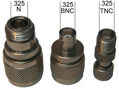
The N,
BNC & TNC connectors all have the same 50 Ohm
interface.
Adapters: Nf-HNm, BNCf-Nm, TNCf-Mini_UHFm
|
|
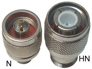
The Nm
on left and the HN (High Voltage N) on the right.
The N O.D.of the ground sleeve is close to 0.325".
For the HN the ground sleeve O.D. is about 0.555".
|
2540012
Electrical connector,
Octavio
M Salati,
Hazeltine
Res, App: 1945-05-19, W.W.II, Pub: 1951-01-30, - connector
for 1/4" coax, stepped Z rather than taper.
6609925B1
Precision BNC connector,
James
Edward Cannon,
Agilent,
2003-08-26, - makes it suitable for use up to 18 GHz in precision
applications.
In the 1960s when I was working with these connectors the male
connector was made by starting with some 0.141" OD simi-rigid
coax cable which was similar to a copper pipe with Teflon
insulation and a copper center conductor. 50 Ohm
impedance. The shield and insulation were cut without
nicking the center conductor and a nut assembly slipped over the
coax outer conductor and soldered in place. The center
conductor acted as the male pin. Pasternack
Enterprises PE4007 is an example.
The female center pin has springy fingers that grab the male
pin.
I learned a number of ways of making microwave male and female
SMA connectors to be part of a number of products like detectors
(Shrike missile) or the ALR-54 front end limiter-detectors and
many other products that used SMA(m) microwave input connectors
and SMA(f) output connectors. The key things were to get
the spring into the female center contacts by choosing the metal
alloy and heat treatment and capturing the male and female
center contacts so that they did not move.
RG-174 Coax Connectors
Note that this cable comes in many flavors. Some are for use
in applications where low Triboelectric noise (
Wiki)
is important, like vibration sensors on shake tables.
Here is some quick ID info for common coax connectors used with
small diameter coax like RG-174:
50 Ohm SMA uses a 1/4-36 thread
50 Ohm SMB these are the push on type where the diameter of the
part with the male pin is 0.144"
75 Ohm SMB these are the push on type where the diameter of the
part with the male pin is 0.243"
50 Ohm SMC uses a 10-32 male thread on the part with the male pin
and also has a body diameter of 0.144"
75 Ohm SMC uses a 0.3125-32 thread
SSMB
looks
like SMB but has a body diameter of 0.104"
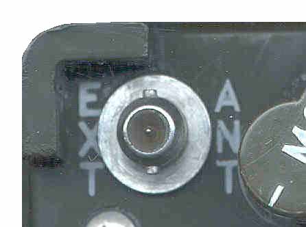
The antenna connectors
for the AS-2108 DF antenna are not there, anyone know what
these are (one has 2 lugs, the other 3 lugs)?
Most of these are standards, except for the antenna connector on
field radios, which are much more rugged than normal connectors.
Amphenol coax
web page with drawings for most types
Kings Electronics -
aerospace
& RF -
Pasternack Enterprises -
Good Connector ID info - Minimum PO is $100 and $10 per line.
Pomona Electronics
-
S. M. Electronics - On
line, photos and 1 each pricing
The R.F. Connection - RF and
other connector types + adapters
Tower Electronics -
carries the 3.5mm to SO-239 needed for the BK radios RF jack.
Trompeter -
Also see my distributors web page for
more sources.
GR 874 (Wiki)
Like the ARES configuration of the Power Pole DC connector, the
coaxial connector is hermaphroditic and also 50
Ohms.
The General Radio Experimenter, Vol XXIII, No. 5 Oct 1948:
A Radically new coaxial connector for the Laboratory. (GenRad_Experimenter_Oct_1948.pdf)
- Test data up to 4.5 GHz.
2548457
Coaxial connector for high-frequency transmission lines, Harold M
Wilson, General
Radio, App; 1947-01-10, Pub: 1951-04-10, -
Telegraph era
Also See the Telegraph web page
for Binding Posts, phone tip, Fahnestock Clip, etc.
USB
2024 Jan YouTube: If not
properly used. Make USB-C work (Connector, Cable, PD, Data
Transfer, Devices), 26:07
On Order:
ChargerLab.com
Power-Z
KM003C USB C Tester - YouTube
Review, 19:11 - 0 - 50 V, 0-3A,
C2C
CABERQU - USB-C Cable Tester with case
Connectors
Width
|
USB 1
|
USB 2
|
USB 3
Wiki: USB-C
USB 3.2
|
|
Type-A: 12 x 4.46mm
Type-B: 8.45 x 7.26 mm
USB 2.0
Mini-B
6.8 wide x 3 mm
Micro-B
6.85 wide x 1.8mm
|

|
USB 1.x/2.0 Miniplug/Microplug
| Pin |
Name |
Color |
Description |
| 1 |
VCC |
Red |
+5 V |
|
|
|
|
| 2 |
D− |
White |
Data − |
| 3 |
D+ |
Green |
Data + |
| 4 |
ID |
none |
permits distinction of
Micro-A- and Micro-B-Plug
Type A: connected to Ground
Type B: not connected
|
| 5 |
GND |
Black |
Signal Ground |
|

|
|
|
 |
|
|
A = 12 mm wide
4.46 mm thick
B =
8.45 mm wide |
Micro-B= 5.2 mm
wide
Mini-B
=
6.8 mm wide
|
C: 8.25 x 2.4 mm
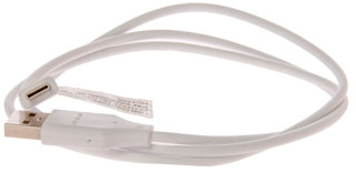
LG-998T G6 phone
USB Data Cable, DC1709
The USB 3 Micro-B is like two connectors side-by-side
and is used on external USB hard drives.
|
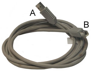
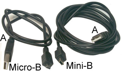
There are (July 2009) three
connectors:
- A is the computer connector
- B is the large (first) device connector
- Mini-B is the (second) medium sized device connector
- Micro-B is the (third) smallest sized device connector
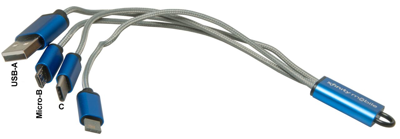
USB-A to Multi Phone
Charging Cables
This would be a good match with a Solar Phone Panel.

|
Left to Right:
USB-A input
USB Micro-B phone connector
USB-C phone connector
Apple Lightening? (Wiki)
phone connector marked "down" the other side marked "up".
|
USB Power Delivery (Wiki)
The maximum current for a USB device (Wiki:
Allowable Current Draw) varies between 0.1 and 5 Amps at 5
Volts. But Power Delivery devices for USB-C 1, 2 or 3 it is
up to 20 Volts & 5 Amps (100Watts). For the newest USB-C
3.1 Power Delivery devices it's 48 Volts & 5 Amps
(240Watts). Note Starlink uses PoE (Wiki)
with 56 Volts @ 1.6 Amps (89 Watts).
While the Wiki page says Power Delivery was made part of the USB
spec in 2012, it's only in 2023 that I learned about the "ZYPDS
ZY12PDN USB-C Type-C PD2.0 3.0 to DC USB Fast Charge Trigger Poll
Detector". This device can be used to test a USB power
source to see what voltages it can deliver and also be used to
make up power cables from USB-C to 9, 12, 15 or 20 Volts.
2023 June 23 (Wiki):
Voltages: 5, 9, 15, 20, 281, 361 & 481
Volts with up to 3 or 5 Amps. (240 Watts max). This applies
to Power Delivery certified USB-A, USB-B (and USB-C?) cables.
Note 1: Requires electronically marked EPR 5 AMp. cables.
NOTES
ON USB PD TRIGGERS (AND ZY12PDN INSTRUCTIONS) -
ZY12PDN The colors indicate:
- Red; Selectable mode, 5V present
- Yellow: 9V
- Green: 12V
- Ice/Teal: 15V
- Blue: 20V
Git Hub:
manuelbl
/ zy12pdn-oss -
HDMI
High-Definition Multimedia Interface (Wiki)
replaced the old analog video cabling. It's required in
order to get high-definition images since it includes
High-bandwidth Digital Content Protection (Wiki).
If you use prior art analog cable to connect a DVD player to a
monitor the HDCP will limit the output quality to that of a VHS
tape. The people that use Yellow, White & Black RCA
cables, or other analog cables on their DVD players are degrading
the image quality.
My Nikon D800E camera has a mini HDMI jack so I'm learning about
the three sizes of HDMI connectors: full size, mini and
micro. Not all eBay sellers properly label their products.
Fig 1 HDMI (standard) male to HDMI mini
male cable
The correct one to connect my D800E to the monitor

|
Fig 2 Showing mislabeled adapter.
It is an HDMI mini female to HDMI micro male

|
0.1" Headers
First generation printed circuit boards used DIP (Wiki)
packaged parts where the pitch was 0.1" and the separation
between rows of pins was an integer multiple of 0.1". This
means that the board would be laid out on a gird that's 0.1" x
0.1". Most through hole components (Wiki)
fit nicely on this grid. One of those components is the
Pin Header (Wiki).
The first generation have a pitch of 0.1" and have many uses.
Metric
Note that 2.54mm is exactly the same as 0.1" So
you will see Molex KK 254 and Molex KK 0.1" which are
identical parts. It's very common to see this sort
of exact conversion of an inch unit to a metric unit
where both parts are interchangeable.
But what is NOT identical are parts that have a
pitch of 2.5mm. Note these parts are not
interchangeable with inch parts!
|
LCD modules typically have the interface connector laid out for
a header or ribbon cable, for example see: PIC 16F88 LCD Interface.
The hole pattern for an 8-pin header is on the 6 digit 7-segment display board
of 22 Feb '03.
Sometimes jumpers are used in combination to select
options. Either the jumper is installed or not installed
to choose.
On YouTube: BigCliveCom: Crimping
tool test that I screwed up. (Read description.) - uses
2-contact versions for wiring up low voltage battery and solar
circuits that typically involve LEDs.
Example of using these: salvaged lithium cells to
power LEDs directly. (with protection test) -
Parts on order (2020 March 9):
22-01-3027 Housings
08-50-0114
plain Terminals
11-01-0185 CR2262C crimp tool
08-50-0032 cat's ears terminal
22-23-2021 2-pin locking header
Hints
- The Molex tooling is dependent on the actual
terminal part number. So you will NOT find crimp
tooling information on their web pages associated with
the housings. Not only is there tooling information on
the terminal web page and there is also information on
previous tooling that's very handy when searching eBay
for used crimp tools.
- The black resin parts seem to be stocked mostly in
the EU, probably because of ROHS (Wiki)
requires higher soldering temperatures.
|
Wire Termination, 2-circuit housing Molex
22013027 (eBay: 22-01-3027)
Headers that mate with 2222-01-3027 Housing-01-3027 Housing
Header
|
Polarized
|
Material
|
Pins
|
| 42375 |
no
|
Black resin
|
Straight
|
| 42376 |
no
|
Black resin |
Right Angle
|
| 42377 |
no
|
Black resin |
Right Angle |
| 4030 |
no
|
Nylon
|
Straight |
| 6373 |
yes
|
Nylon |
Straight |
| 6410 |
yes
|
Nylon |
Straight |
| 171856 |
yes
|
Black resin |
Straight |
| 171857 |
yes |
Black resin |
Right Angle
|
Terminals
KK 254 (0.1") Crimp Terminal
Note 1: there are other terminals in each Series, I'm just
showing one of them. See the Series page for a list of
terminals.
Note: Phosphor Bronze has more springiness than Brass so may
offer a better mechanical & electrical contact. Need
to check the spec sheets to see.
Note: There are versions of the terminals that have gold
plating on either the wire crimp or both the wire and
insulation crimp.
Note: Have an open question to Molex about "Cat's Ears".
Mating 2-circuit Headers
Note these are
designed to be soldered on a PCB, not terminated on a
wire. But Big Clive is just soldering wires to them to end
up with a wire-wire connection.
p/n
|
Polarized
|
Angle
|
Lock
|
Body
Material
|
| 42375 |
no
|
straight |
none
|
Black
Resin
|
| 42377 |
no
|
straight |
none |
Black
Resin |
| 42376 |
no
|
Right |
none |
Black
Resin |
| 4030 |
no
|
straight |
none |
Nylon
|
| 6373 |
Yes
|
straight |
Friction
|
Nylon |
| 6410 |
Yes |
straight |
Friction |
Nylon |
| 171856 |
Yes |
straight |
Friction |
Black
Resin |
| 171857 |
Yes |
Right
|
Friction
|
Black
Resin |
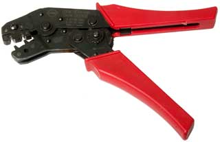
Crimp Tool
While (as of March 2020) the current tool is the 638118200 older tools
still work and can be used such as the 11-01-0185 and the 69008-0955. I found this 11-01-0185 on
eBay for a fraction of the cost of a new tool.
Markings: Molex, 11-01-0185, ENG# CR2262C,
A 22-24 AWG
B 26-30 AWG
Made in Sweden
J455255
999129
This tool includes both wire crimp and insulation crimp on
each cycle. The optional Locator Blade that helps
position the terminal did not come with it.
The maximum insulation diameter is 1.57mm (0.0615" or about
1/16").
Photos
Fig 1
|
|
Wire
For the "A" notch in the crimp tool the range includes 22
& 24 AWG. The "B" notch includes 26, 28 & 30
AWG, so I have some 28 AWG wire on order that complies with
Mil-W-16878/1. The specs are:
| Part
Number |
Construction |
Insulation |
Insulation (in) |
Nom. OD (in) |
Temp. |
Volt. |
Product Type |
| 9302 |
28 (7x36) TC |
PVC |
.010 |
.035 |
105 |
600 |
Mil-W-16878/1 |
The nominal OD of 0.035 is about half the allowed the maximum
diameter.
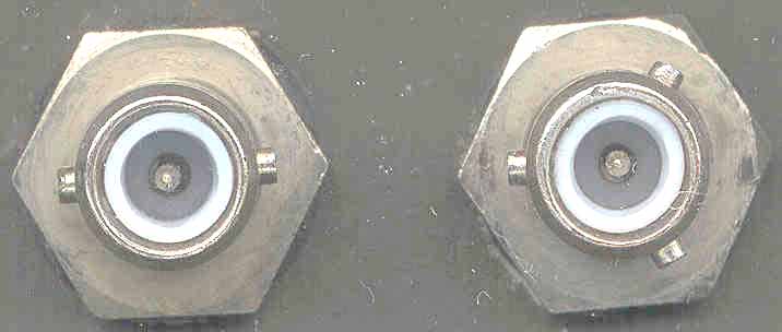
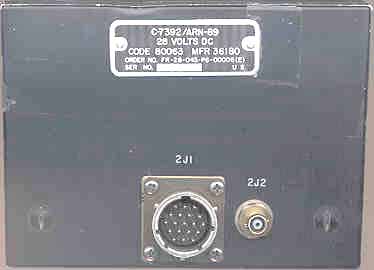
Unknown - Wanted
They all are coax connectors with a male pin for the
center conductor and have 2 or 3 lugs for the mating connector.
Looking for the mating connectors to make up cables.
Manufacturer might be Dage.
|
Where Used
|
AS2108/ARN-89
|
C-7392/ARN-89
|
AN/URC-68
|
|
O.D.(inch)
|
0.285
|
0.285
|
0.264
|
|
Photo
|
2-lug & 3-lug
|
2-lug
|

|
|
ID
|
inside the white dielectric is about 0.143"
|
DAGL 1-531-1
5935-783-7232 SM-B-597016-1
|
|
Links
RS Components - Connectors
and Cable -
William Perry Co
in Louisville, KY - Connectors:Amphenol, Bendix, Cannon, Burndy,
Cinch and Winchester
PEI-Genesis -
Brian, at Prime Connectors Inc. recommended on the Army Radios
list-server (no web presence)
Voice line is 1-215-658-0700, FAX is
1-215-658-1495
Nexus - Audio Plugs &
Jacks
Spacecraft Components Corp
- circular and Coax - ARC-114A
Cooper Interconnect - Mil
Connectors
Pasternack Enterprises
- many coax connectors including a connector ID helper
Brooke's Home, Military
Information, Electronics Page
[an error occurred while processing this directive] page created Jan 30,
2001.


