
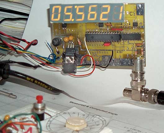
28 Oct 2002 first prototype
6 LEDs working & 1 PPS out working
28 Oct 2002 first prototype
6 LEDs working & 1 PPS out working
6 Digit LED precision clock (HH:MM:SS) where the uC clock source comes from a precision oscillator at 1, 5, 10 or 20 MHz. Because the frequency division is in software it's possible to divide non standard frequencies down to 1 PPS (see below) allowing the use of lower cost yet very high quality oscillators as time bases.Altough I have the TAC32 software and a GPS receiver with it's serial port connected to my computer, I don't normally run the software. I would like to have a hardware clock driven by my precsion oscillators as a check of their health.
Ideas
It may be possible to offer an optional version that would display Sidereal time for astronomical use by swapping the uC for one with a different program.By arranging the digits side by side and using the decimal point as the separator between hours an minutes and a blinking decimal point between minutes and seconds the display might also be used as a frequency or time counter with a different microcontroller installed.
Status
Developing the software routines for the three projects below using the PIC 16F870. This chip has the same modules needed for the MM5369A products below and has a number of extra I/O pins that can be used for development. It also is more cost effective than using a smaller PIC for the 6 Digit Precision Clock than using a smaller PIC and then adding extra chips to get the needed I/O pins.
7 Oct 2002 - have interrupt routine working
10 Oct 2002 - have single 7-segment digit that will display a 16 bit value as 4 sequential hex digits for development
12 Oct 2002 - have 10 bit A/D working to be used with thermister for temperature sensing
28 Oct 2002 - received prototype PCB and after fixing the errors have the 1 PPS output and 6 digits turning on.
7 Nov 2002 - trying to get the Microchip ICD2 In Circuit Debugger version 2 working
19 Nov 2002 - Investigating the idea of using a 12F675 8 pin PIC 6 digit clock (maybe more) that would be able to drive any size of LED digits.
Starting prototype to try out the idea. No RS-232, only runs from 10 MHz unit oscillator.
Many years ago National Semiconductor made an IC that contained an oscillator that worked with the common color burst crystal (3.579545 MHz) and divided down to a 60 Hz output. This part is now obsolete. To make a replacement today it costs less to use a unit oscillator than it does to use a separate crystal and loading caps. Also using a microcontroller allows either 50 or 60 Hz outputs as well as a 1 Pulse Per Second output.14 Oct 2002 - Prototype is working with the following features:
15 October 2002 - 12 MHz was chosen because it's evenly divisible by both 100 and 120 allowing the generation of either 50 or 60 Hz, but a better choice would be 20 MHz because it's the highest rated frequency for most of the modern PIC chips. Most low cost unit oscillators have a frequency tolerance of 100 ppm (Parts Per Million) including voltage and temperature and 30 days of aging which translates to 2,000 Hz in 20 MHz. On the 20.0 MHz unit oscillator I have the frequency was fast by about 100 Hz. So the correction for starting frequency would also correct for the 120 and 100 division. The higher frequency translates into finer corrections.
- 12 MHz unit oscillator as clock for 12F675
- Jumper selection of 50 Hz or 60 Hz output
- 1 Pulse Per Second Output with 200 ms on time for either 50 or 60 Hz output.
- adding a first order frequency correction since there is no frequency adjustment on the unit oscillator. This changed the 1PPS period from 1.000,008 Seconds to 1.000,000,2 seconds, an improvement of about 40 times.
The inexpensive unit oscillators behave about like a plain crystal in terms of frequency errors due to temperature and aging. It may be possible to greatly reduce these errors not be trying to control the frequency but rather by controlling the 50/60 Hz output and the 1 PPS output. This requires both temperature sensing and characterization of the oscillator being used for not only it's current frequency but also how the frequency changes with time (aging rate). Since crystal oscillators are many orders of magnitude poorer than atomic frequency standards the crystal aging can be characterized in a relatively short time when an atomic standard is used as the reference.Idea: 14 Oct 2002 - use a pot on AN1 as a switch that's only read at power up (that way it can not change) that would allow selection of:
The 1 PPS LED can be used to indicate which mode was selected during the power up sequence then it changes to the 1 PPS heartbeat.
- no corrections
- Fixed frequency correction
- Aging frequency correction
- Temperature correction
- Fixed Freq & temp cor
- Aging & temp
- Maybe allow programming delta changes to the corrections at power up? The 12F675 has a small EEPROM data memory so could remember these changes. This EEPROM memory is needed to make the aging correction.
An alternate use of AN1 might be to use a pot that has no stops and allow continuos frequency correction similar to a variable cap on a crystal but with way more range and resolution.
There are a number of oscillators on the market (eBay) that have output frequencies that are not the classical precision oscillator frequencies (1, 5 and 10 MHz). For example the FEI model FE-2163A is a very high quality double oven unit with extremely good specs but it's frequency is 10,054,347.8 Hz.. I think this frequency can be divided down to exactly 1 PPS using a uC allowing it's use as a precision time standard.Table of common crystal and unit oscillator frequencies and their factors, typically 2, 3 and 5. Up to 30 MHz which is the highest I have seen a 16F870 or 16F873A run.
 17 Nov. 2002 - Testing
various unit
oscillators. The Jameco
10 MHz full size unit is marked Pletronics, P1100-3State,
10.000MHz,
Korea
9037J. The frequency display with 1 sec gate shows about 0.1
Hz
variation. The Allan variance (Jitter on the SR620) is
0.0215 (on
the Frequency) when the Allan variance is measured on the 1 PPS
output
it's about 1.5 nS. Both of these measurements were made at
room
temp (20.3 C)
17 Nov. 2002 - Testing
various unit
oscillators. The Jameco
10 MHz full size unit is marked Pletronics, P1100-3State,
10.000MHz,
Korea
9037J. The frequency display with 1 sec gate shows about 0.1
Hz
variation. The Allan variance (Jitter on the SR620) is
0.0215 (on
the Frequency) when the Allan variance is measured on the 1 PPS
output
it's about 1.5 nS. Both of these measurements were made at
room
temp (20.3 C) 21 Nov 2002 - a different Jameco 10 Mhz Pletronics oscillator used in the prototype 12F675 6 digit clock using Allegro 6276 digit drivers has an Allan variance on the 1 PPS output of about 113 pS and the 1 PPS period is about 1.000,003,445,405 seconds.

26 Nov 2002 - The PIC 12F675 based clock is now counting time with wiring that matches the design of a single sided PCB. With the Allegro 6276 serial LED drivers only 3 PIC pins are needed for the display and the display is only updated when there is a change making the software much simpler than for a muxed display. Also the LEDs are on constantly and their brightness is controlled by a set resistor so the brightness can be very good, now it's limited by the current capability of the the HP 6216A power supply, but is easily changed via the current set resistors.
I set the time displayed on the 12F675 clock to be within a
fraction of a second of the time shown on the 16F843A
clock. The
16F843A is
driven from a Rb locked oscillator and the 12F675 is driven from
a low
cost
10 MHz unit oscillator. Within 8 hours they differ by just
under
1
second.
|
|
|
|
1 sec of Error |
24 hours |
400 ns error1 |
Time for 100 ns 10 MHz period2 |
|
|
|
|
1 m 43 s
|
14 m 24 s
|
40us
|
10 us |
|
|
|
|
16 m 40 s
|
1 m 26.4 s
|
400us
|
100 us |
|
|
|
|
2 h 46 m 40 s
|
8.6 s
|
4ms
|
1 ms |
|
|
|
|
1 d 3 h 46 m 40 s
|
0.864 s
|
40ms
|
10 ms |
|
|
|
|
11 d 13 h 46 m 40 s
|
86.4 ms
|
400ms
|
100 ms |
|
|
|
|
115 d 17 h 46 m 40 s
|
8.64 ms
|
4s
|
1 s |
|
|
|
|
3 yr 62 d 9 h 46 m 40 s
|
864 us
|
40s
|
10 s |
|
|
|
Double oven Xtal osc |
31 y 259 d 1 h 46 m 40 s
|
86.4 us
|
6m 40s
|
100 s |
|
|
|
|
317 y 35 d 17 h 46 m 40 s
|
8.64 us
|
1h 6m 40s
|
16m
40s |
|
|
|
|
3,170 y 357 d 9 h 46 m 40 s
|
864 ns
|
11h 6m 40s
|
2h 46m
40s |
|
|
|
31,709 y 289 d 1 h 46 m 40 s
|
86.4 ns
|
4d 15h 6m 40s
|
1d 3h
46m 40s |
|
| 1E-13 |
Cs
osc |
317,097+
years |
8.64
ns |
40
days |
11d 3h
46m 40s |
|
| 1E-14 |
Cs osc |
3,170,979+
years |
0.864
ns2 |
400
days |
115d
17h 46m 40s |
|
| 1E-15 |
NIST
Cs
Fountain osc |
31,709,791+
years |
86.4
ps |
4,000
days |
3 yr 62 d 9 h 46 m 40s |
Note 1: A 10 MHz unit oscillator driving a PIC microcontroller will have an instruction time of 4/Fosc = 400 ns, so the time in this column is how often the PIC would need to change the divisor used to count down to one second to correct for crystal aging.
Note 2: If the time interval between zero crossings
of
a 10 MHz signal is used there will be rollover seperated by a TI
of 100
ns, i.e. the period of a 10 MHz signal. If you can
go for
many days without a rollover then you're working with an atomic
standard.
Note3 : By averaging the 1 PPS from a GPS receiver
with
everything else optimized you can get about 1 ns for a day's
worth of
data. The newer Carrier Phase GPS Time Transfer method is
good
for about 3 ns on a second by second bases and could be averaged
to
improve that. This change per day is the practical number
here,
most quality time interval counters, like the SR620 or the HP
53--
series can repeatably measure in the 1 ps range.
In addition to the stability above there are frequency errors
due
to the initial frequency setting and due to temperature changes.
The above table could be used where "stability" means only aging
or it
could be used where "stability" means the combined stability due
to
some specified list of parameters like initial aging plus
temperature
plus supply voltage, etc.
6 Dec 2002 - Very minor temperature changes show up in the oscillator frequency. A desk lamp shining on the unit oscillator from 3 feet away will change it's frequency by a few Hz. When a cold oscillator is first turned on it takes a number of minutes for it to warm up and in the process it drifts more than 10 Hz. Insulation of the unit oscillator to minimize the temperature fluctionations is desirable.
In terms of a test method looking at only the delta between the 12F675 1PPS output and the house 1PPS is not enough. That data needs to be saved or the test needs to be done at an interval of 24 hours in order to see how well the clock can measure a full day. By doing this minor fluctuations will have a chance to be averaged out. For example if there is a time lag between an oscillator temperature change and the correction there will be some error as the temperature rises and there will also be an error as the temperature falls but the cumulative effect of the two errors will tend to cancel each other.
17 Dec 2002 - have been testing the Rakon
- CX0600C
10.0 MHz unit oscillator. Looking good so far. These
are
reasonably priced.
7 Jan 2003 - Working on 6 digit 0.56" char ht LED board with 3
each
6276 chips.
Voltage
sensivity of Sentry 20 MHz unit oscillator is about 367 Hz per
volt (nominal 5.0 Volt supply).
Common
3 terminal voltage regulators have less than 0.1% change over
the
0 to 50 deg C range.
This
translates to 0.1 * 1/100 * 5 V * 367 Hz/V = 1.8 Hz over temp
due
to voltage stability of the oscillator.
20 Feb '03 - stopped testing the Rakon sample #2 - is't drifting
down
in frequency about 2 Hz per day. It and the CTS sample
(see 29
Oct '02 above) apparently are leakers. Maybe these two
were
assembled in facilities with poor QA?
20 Feb '03 - The Sentry oscillator has been running at room temp
will
now be moved into the temperature chamber.
22 Feb. '03 -
After the frist couple of days The frequency seems
to be drifting down about 0.01 Hz per day, but it's still early.
 22 Feb.
'03 - Have received
the prototype LED1 single sided printed circuit boards.
Holds 6
each 0.56" character height 7 segment LED digits. The
digits can
be installed all right side up to provide a pure numeric
display with decimal points with each digit, or every other
digit can
be
installed upside down providing a ":"
resulting
in a clock hh:mm:ss display. It uses 3 each Allegro 6276
driver
ICs. The board has 8 pin 0.1" headers on each side so
multiple
boards can ba
cascaded to a 6, 12, 18, 24, 30 digit display.
22 Feb.
'03 - Have received
the prototype LED1 single sided printed circuit boards.
Holds 6
each 0.56" character height 7 segment LED digits. The
digits can
be installed all right side up to provide a pure numeric
display with decimal points with each digit, or every other
digit can
be
installed upside down providing a ":"
resulting
in a clock hh:mm:ss display. It uses 3 each Allegro 6276
driver
ICs. The board has 8 pin 0.1" headers on each side so
multiple
boards can ba
cascaded to a 6, 12, 18, 24, 30 digit display.
1 March 2003 - some parts, indlucing the PC2 PCBs have
arrived,
but not all of them.
1 March 2003 - The sentry oscillator's iinitial rate was aging
down in
frequency at 1 Hz per day, but the rate is now slowing.
16 March 2003 - New web page for LED1
Display
& 12F675 based PC2 clock.
16 March 2003 - The Sentry 20 MHz Frequency vs. time is very
close to a
parabolic curve. This may be due to cleaner manufacturing
than
the
other unit oscillators. Note that the lower frequency
crystal
blanks
are thicker so that the aging is proportionally less.
18 May 2003 - The Sentry oscillator is following y = 1E-08 X^2 -
0.0026X
+ 1E+07 (Excel equation, not accurate) so in 12.5 weeks the
frequency
has
gone down by 35 Hertz.
17 April 2004 - The Sentry oscillator has been running in the
120
F oven for about 395 days and the aging rate has now decreased
substantially.
y = -35.858Ln(x) - 84.952 R2 = 0.9933 the raw data into
this plot
is the frequency difference from 20,000.00000000 MHz, the
nominal
oscillator frequency. x is the number of minutes computed
from
the time and date. 4/17/04 9:16 am is x= 683893 minutes
since the
start of testing (12/29/02 11:13 am) and the offset (y) from
exactly 20
MHz is 1,121.343 Hz. The SR620 counter is actually
measuring the
period of the 1 PPS output from the PIC down counter and the
actual
frequency es calculated in the spreadsheet.
At the start of the test the frequency was low by about 980 Hz
and
now after 395 days of high temp operation it's about 1,120 Hz
low.
At the start of the test it took about 20 days to age down by 20
Hz. The last 20 Hz decrease has taken about 136 days and
the.
|
|
|
10 Mhz oscillator |
|
|
|
|
|
|
to 1E-7 |
to 1 Hz |
|
|
|
|
|
|
|
|
Ideas for improving temp stability without using a heater
Patents related to Disciplined Oscillators -
Bresenham's algorithm
These links are about a method where a fixed Timer count is used and so results in a jitter on the 1 PPS output as large as the size of the Timer count. A much better way is to accumulate the fractional timer count error and add one count to the last count of the second and subtract 1 from the fractional error counter. This way the jitter is limited to one timer count = 1 instruction count = 4/Fosc.Of course this requires using a different value for the Timer count at different times in one second. For the FEI FE-2163 double oven 10,054,347.8 Hz oscillator this would translate to 99 rollovers at a Timer1 count of 25,058 and a nominal last count of 32,844, but because of the fractional part overflow for 19 seconds in a row the last count would be 32,845 and once every twenty seconds the last count would be 32,844 resulting in zero error and jitter less than 397.8378 nanoseconds.
Zero-error One Second Timer! - I'm not using this method, but it could be applied differently for much better results
NIST -Dictionary of Algorithms and Data Structures - Bresenham's algorithm - the basis of the Zero-error timer
Bresenham Line-Drawing Algorithm -
Wiki - Bresenham's line algorithm -
Back to Brooke's Products
for
Sale, Time &
Frequency,
Military Information, Home
page
This is the [an error occurred while processing this directive] time this page has been accessed since since 13 June 2002.