E-89-A Telephone Repeater
© Brooke Clarke 2013 - 2024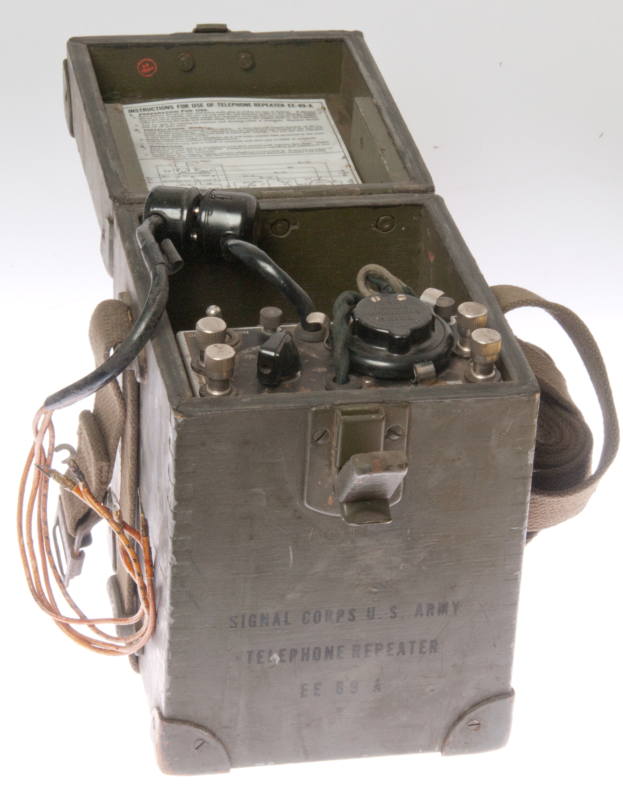
These were used to increase the reach of phone lines. The neat thing is that it's an amplifier that amplifies the signal between A and B as well as the signal between B and A, that's to say each terminal pair is both an input and an output. For this to work the lines need to have the same impedance looking each way from the amplifier. The functional check is to short either the input or output and listen on the earphone to see that the amplifier is oscillating at all attenuation settings.
There are two ways to power this repeater: either use a BA-40 combined 1.5 & 90 Volt battery by means of the 4-prong plug, or use seperate BA-23 (No. 6) 1.5 V battery and two BA-36 45V batteries in series by means of the 4-prong socket to 4-wire cable.
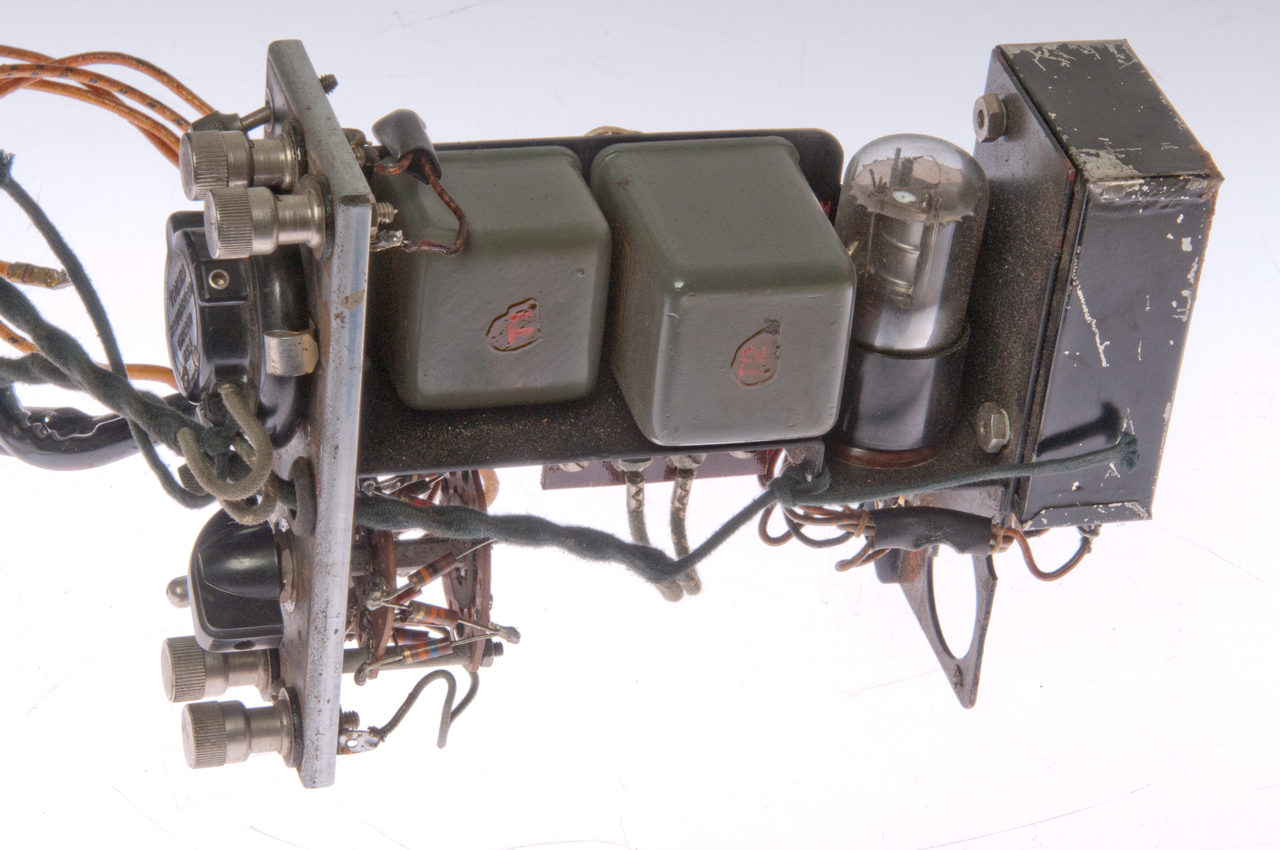
The single tube is the VT221 (3Q5GT). There's a single Trimm earphone to monitor conversations going in either direction.
To test operation just short either pair of line terminals and there should be oscillation at all settings of the attenuator.
Normal 20 Hz ringing can be employed on lines equipped with these repeaters. Ringing signals are transmitted through the repeater.
Made when W-110-B was the common filed wire, but will work with WD-1 field wire.
Photos
Fig 1 Overall view
Signal Corps U.S. Army
Telephone Repeater
EE-89-A
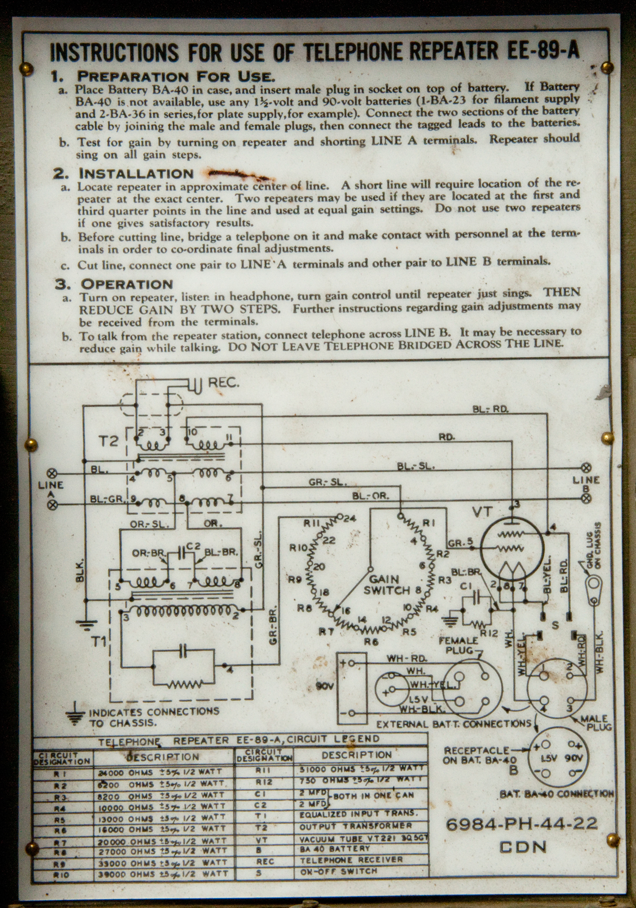
Fig 2 Instructions & Circuit
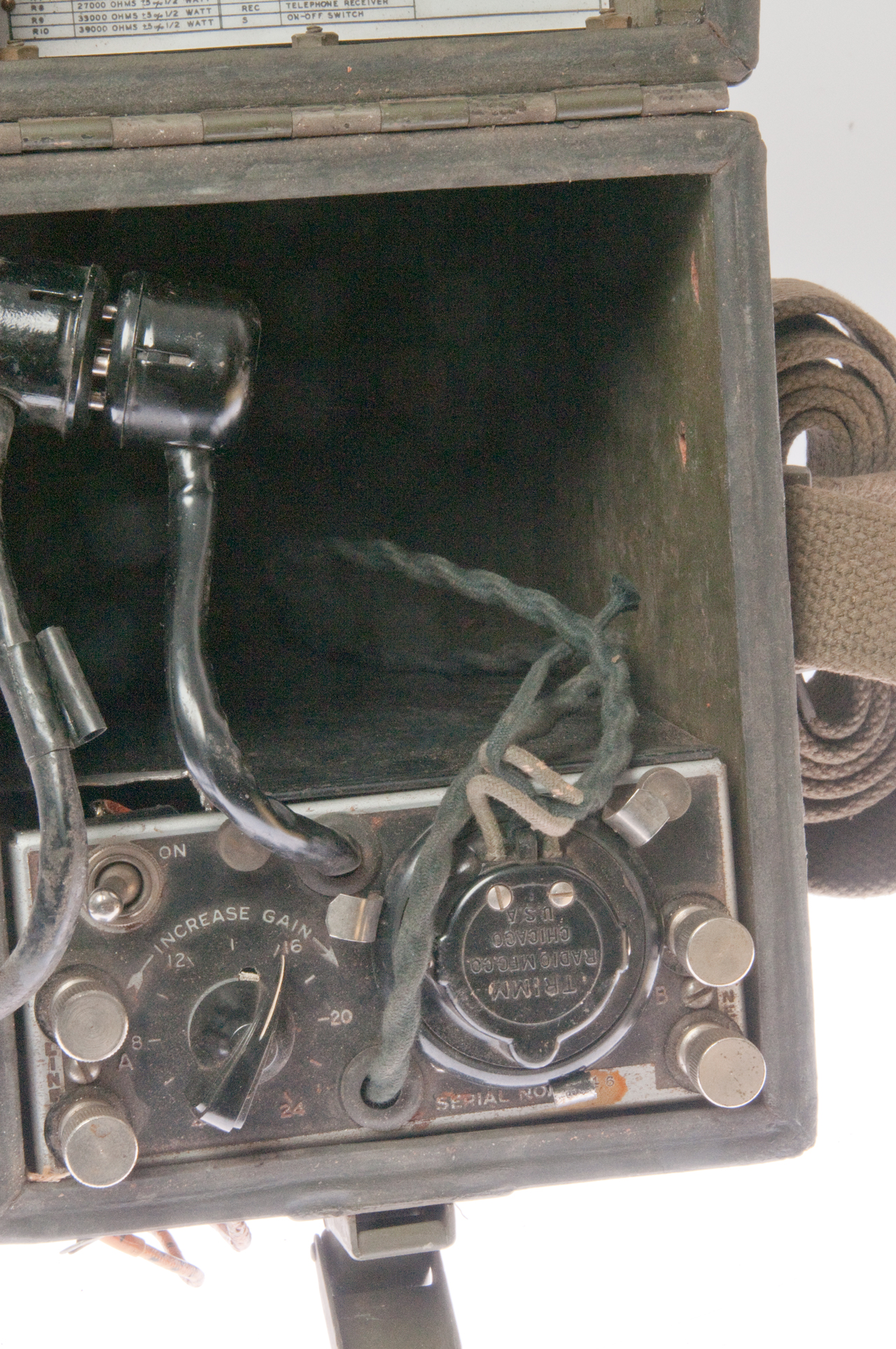
Fig 3 Battery Box & Front Panel
Fig 4 Front Panel
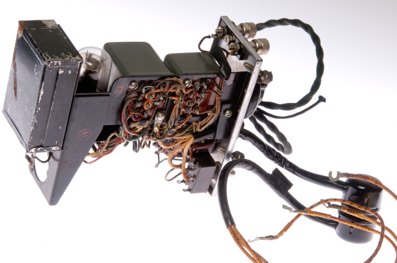
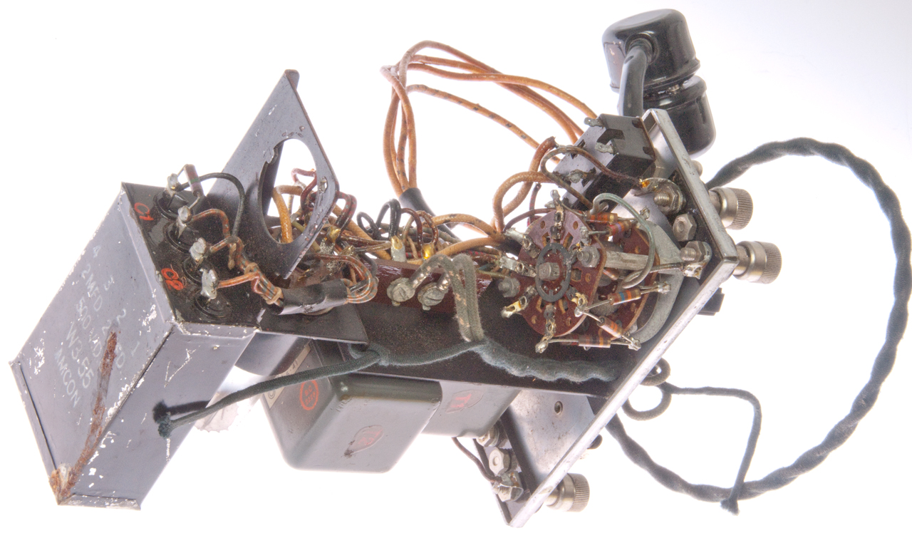
Fig 5 Inside top left
Fig 6 Inside back right
Fig 7 Inside Bottom
Operator
Short Line A terminals and hear if the unit sings into the earphone at all attenuation switch settings.
Depot
- Connect EE-8 field phone to Line A and speak into handset. E-89 headphone should produce speech.
- Check for continuity between top Line-A and top Line-B also check between bottom Line-A and Line-B. Both should be between 35 to 45 Ohms.
- Voltage check at tube socket. Between filament pins 7 & should be about 1.5 VDC as well as between 2 & 8. Plate voltage between pin 3 & 8 should be at least 80 VDC.
- TM 11-4407 contains tests for the major components as well as line impedance tests to verify the hybrid coil is working.
TM 11-2006 July 1943 Operation, Moistureproofing &
fungiproofing
TM 11-4301 General requirements of repaired equipment (not E-89-A specific)
TM 11-4302 Tactical Switchboards and Long Lines Equipment, Repair Instructions, Apparatus Requirements
TM 11-4407 Aug 1945 - 4th & 5th echelon repair - Repair Instructions, Operational Requirements & Testing (Note: This is a War Department manual)
Patents in general, not specifically for this unit?
The 21-Type Repeater (Lectures in Physics) - single tube amplifier - The EE-89 is a single tube repeater.
Bell System Technical Journal 1931-07: Vol 10; Issue 3 - (sim_att-technical-journal_1931-07_10_3.pdf) - "Negative Impedances and the Twin 21-Type Repeater"
Ref: The Dynatron, A.W. Hall, Proc IRE Feb 1918 (GR Experimenter Vol IV, No. 12, May, 1930)
Passive Repeaters
Also see: Douglas Self\Electromagnetic/Carbon Amplifiers -
542618 Telephone Relay or Repeater, C.H. Arnold, 1895-07-16 -
542619 Telephone Relay or Repeater, C.H. Arnold, 1895-07-16 -
791655 Telephone-current reinforcer or relay, Herbert E Shreeve, AT&T,1905-06-06, -
835037 Telephone repeater circuit and apparatus, Herbert E Shreeve, AT&T, 1906-11-06, -
863230 Telephone repeater circuit, Herbert E Shreeve, AT&T,1907-08-13, -
990365 Telephone repeater-circuit, Carl August Kruckow, McMeen & Miller, 1911-04-25, - the heart is the coil design
1015768 Automatic telephone circuit and repeater, Charles Adams-Randall, Randall Telephone Mfg, 1912-01-30, - uses carbon mike type amplifier
1029724 Telephone-repeater, Frank Joseph Shubert, 1912-06-18, -
1474038 Telephone repeater circuits, Edgar D Johnson, WE, 1923-11-13, - uses carbon mike type amplifier
Tube Type Repeaters
1495422 Transmission circuits, Robert C Mathes, WE, 1924-05-27, - The 21-Type Repeater
1504135 Telephone repeater circuits, Nyquist Harry, AT&T, 1924-08-05, - Type 22 Repeater.
1566311 Telephone-repeater circuits, Alva B Clark, Ray S Hoyt,
1734113 Telephone repeater circuits, Alva B Clark, Crisson George,
1814775 Telephone repeater circuit arrangement, Urmston James, Smith Frederick Stretton,
2223200 Telephone repeater control circuit, Herbert W Augustadt,
2408072
2463379
2601302
2709721
3535475
Telephone Poles
SB-22A Switchboard
SB4170 Military Telephone Switchboard
GRA-39 Radio Set Remote
Z Impedance
Z0 - transmission line impedance including CAT5 and Open wire telephone lines
US Army Signal Corps: Telephone line transmission equipment - EE-89 "Two wire voice frequency intermediate repeater for use on lines with 20 or 1000-cycle signalling. Provides thru simplex telegraph operation. Uses one battery BA-40 which last for about 2 weeks."
Repeater Amplifiers in Either Line Direction, Electronics, Jan 1955 - (407a_bidir_amp%20_1_.pdf) - uses 407A tube at 150 Volts @ 5 mA.
Back to Brooke's Products for Sale, Telephones, U229 Audio Accessories, Audio Connectors, Military Information, Electronics, Home page
page created 2 Oct 2013
