 |
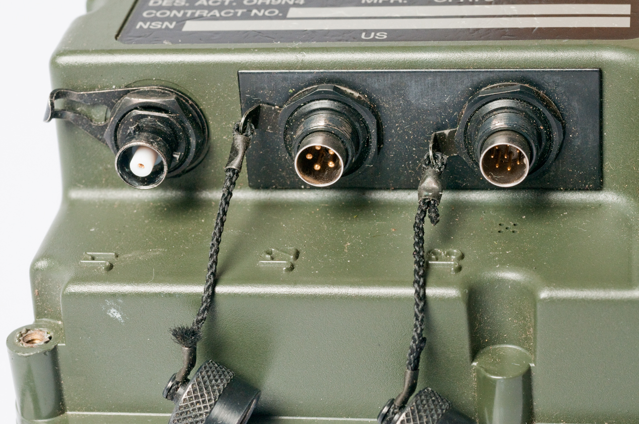
Push Button switch top rear 3 metal threaded inserts at top facing to back & no others  |
 |
| Uses BA-5800/U as primary
battery and came with a CR123 as the memory backup
battery. Notice cract in bottom of primary battery compartment and distortioni in adjacent threads compared to how clean threads are in backup battery compartment. 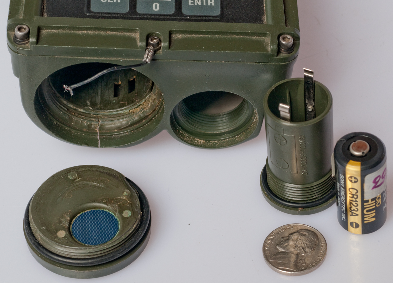 |
5800BA
Battery Adapter Modified for Smaller Diameter &
w/only 4 AA Batteries & with Dentar Floss to Pull Out
of Battery Compartment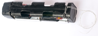 |
Magellan GPS
Commander PLGR DAGR Polaris  |
Inside View There's what appears to be J-B Weld epoxy near the primary battery opening.Not sure where the metal part belongs. Probably at the back of the antenna coax connector. |
Large cap is 0.1F so this
may be a real time clock board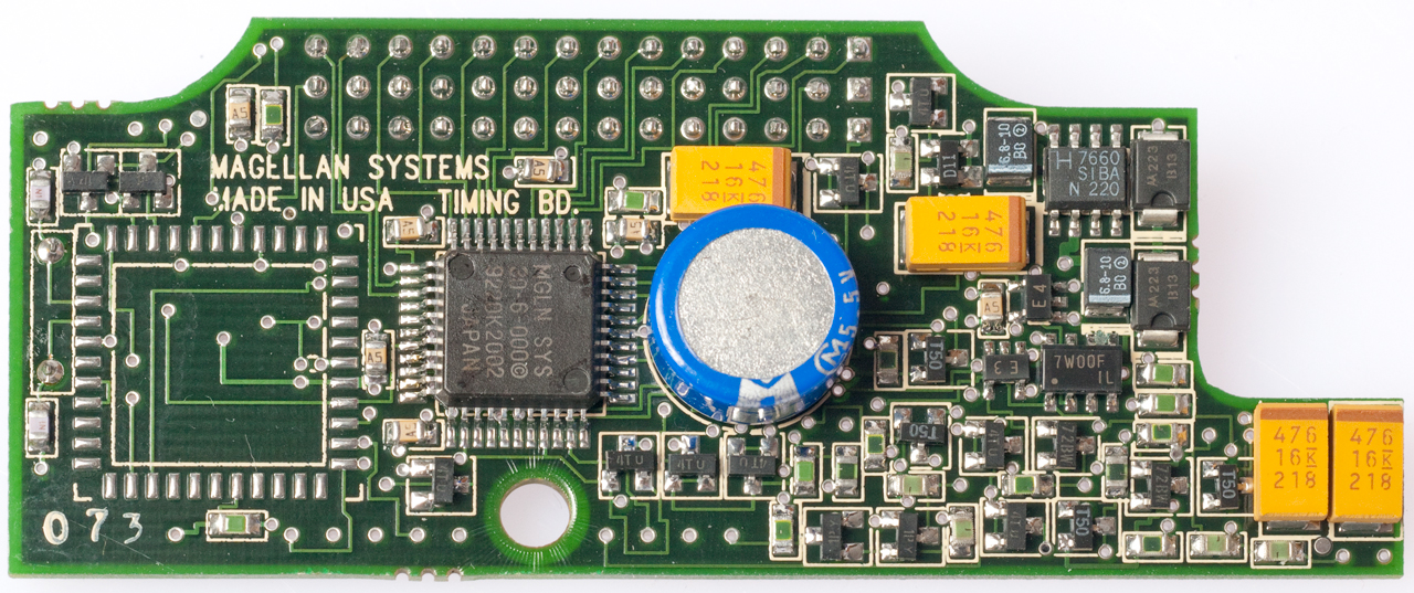 Note missing IC, maybe the crypto chip? |
RF box at left and micro
controller at right top view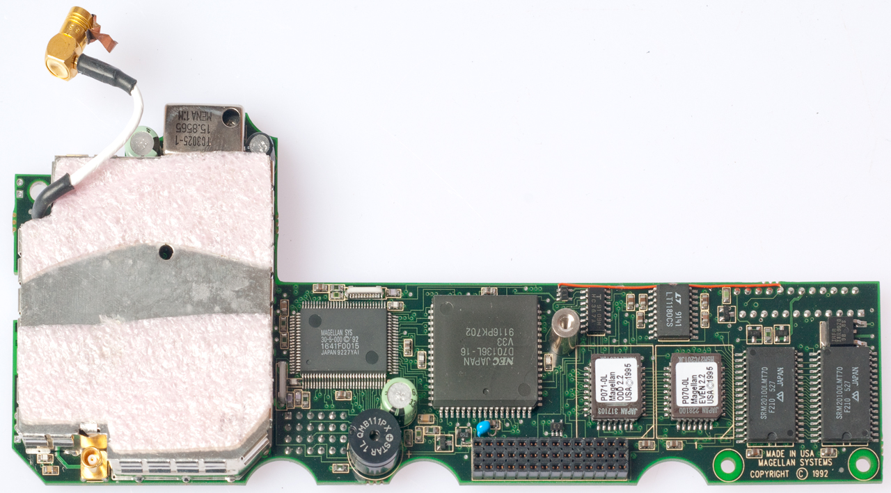 The two ICs with labels (in sockets) are the memory chips that contain the firmware. To the right of them are a couple of RAM memory chips. |
| RF box at left and micro
controller at right bottom view. White connector at lower right is the connector for the flex circuit, difficult to reconnect after soldering the 5 joints. 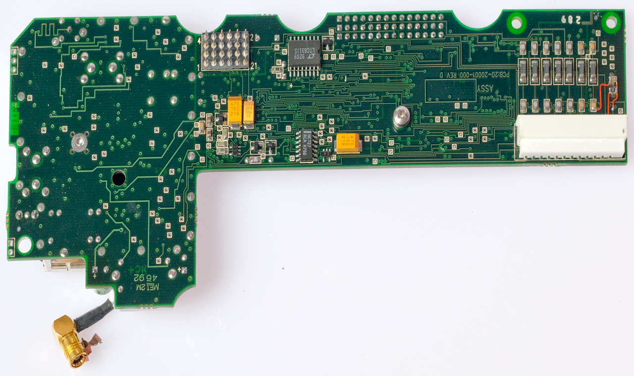 Note the metal strip attached to the antenna coax connector ground. Maybe it was bonded to the metal part shown above? |
back of front panel.
standard 44780 LCD driver chip + keyboard lines.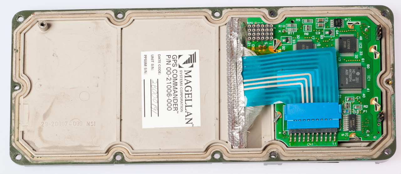 Ther are what appears to be a bundle of fiber optic light pipes that are probably part of the keyboard illumination system. |
maybe PCB is for primary
and back-up battery management? |
5 Unsoldered Connections (What Goes Wrong) Note: Once soldered the "L" shaped board can no longer be seperated from the front panel. After soldering the unit still does not power up. |