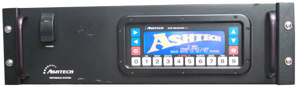
Ashtech Z12 GPS Receiver
&
Z Reference
&
Ranger
© Brooke Clarke 2009 - 2022
Background
Ashtech developed a better way to
use the encrypted L2 signal. The prior art was to square L2
and the Ashtech method has a better signal to noise ratio making
it superior. Also this is the receiver you want for carrier
phase timing, which as of 2009 is still an experimental
development. So I've wanted one for some time.
Getting Started
Antenna Drive Voltage
The output voltage is 9.7 VDC positive on the center conductor of
the Type-N male connector. This will smoke a 5 Volt antenna
like my roof top unit.
Some options:
- Find an antenna rated for L1 and L2 that accepts 10
Volts. This is the desirable solution if it's a geodetic
grade (ground plane or choke ring) antenna.
- Use an L1 & L2 antenna with 5 Volt drive through a
splitter that provides the drive and a DC blocked port to this
receiver.
GPS Source - carries
splitters (and they are on eBay)
GPSNetworking - carries
splitters (and they are on eBay)
- Make an adapter that takes in the +10 volts, regulates it to
+5 and bypass the RF from in to out. <not cost
effective>
Front Panel Keys
Pressing any one key or pressing the Red C or Red e key and any
other key has no effect. i.e. none of the key presses does
anything. This may be a fault or just some arcane way they
figured out to prevent the unknowledgeable from doing harm.
Factory Defaults
Hold down the ^ (up arrow) while
powering up. Enter YES (the number 8 key) when asked if this
is what you want to do.
It now ends up searching for SVs.
Setting External Ref Freq
When the EXT FREQ is set to 0.0 the internal frequency standard is
used, i.e. it's not a requirement to use an external standard.
Press 4, then e, then use arrow keys to highlight EXT FREQ, press
e, set to 10 MHz, then press 3, Wait for screen to change to
Locked, then press e.
If the external reference GPSDO is not locked then the Z12 does
not acquire satellites. Something happened to the
Thunderbolt when there was a power
glitch.
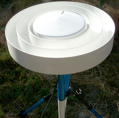
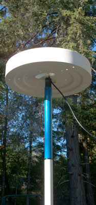
L1/L2 Antenna
AeroAntenna Technology
AT2775-42
with the Choke Ring comprises the
AT2775-42+CR
which has known phase centers for L1 and L2.
Antenna is L1 and L2 runs from 5 to 18 VDC.
For info about the pole and bi-pod see the
DAGR page
NGS NOAA -
GPS Antenna
Calibration
ANTENNA ID        DESCRIPTION                  DATA SOURCE (# OF TESTS) YR/MO/DY

 [north]  [ east]  [  up ]                                   | L1 Offset (mm)
 [90]  [85]  [80]  [75]  [70]  [65]  [60]  [55]  [50]  [45]  | L1 Phase at
 [40]  [35]  [30]  [25]  [20]  [15]  [10]  [ 5]  [ 0]        | Elevation (mm)
 [north]  [ east]  [  up ]                                   | L2 Offset (mm)
 [90]  [85]  [80]  [75]  [70]  [65]  [60]  [55]  [50]  [45]  | L2 Phase at
 [40]  [35]  [30]  [25]  [20]  [15]  [10]  [ 5]  [ 0]        | Elevation (mm)
AERAT2775_42+CR      Marine III +CR adaptor                   NGS (  4) 05/05/31
      -0.1      -2.6      65.7
   0.0   1.2   2.0   2.6   3.0   3.2   3.2   3.1   3.0   2.8
   2.7   2.5   2.5   2.4   2.4   2.5   2.6   0.0   0.0
      -0.1      -0.4      93.6
   0.0  -0.3  -0.4  -0.5  -0.4  -0.4  -0.3  -0.3  -0.3  -0.4
  -0.4  -0.5  -0.6  -0.6  -0.6  -0.5  -0.2   0.0   0.0\
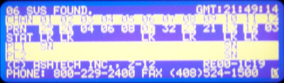
Results
On Page 0 in the linse for STAT, PL1 & PL2 the letters LK
(Lock) appear under all the SVs that are visible.
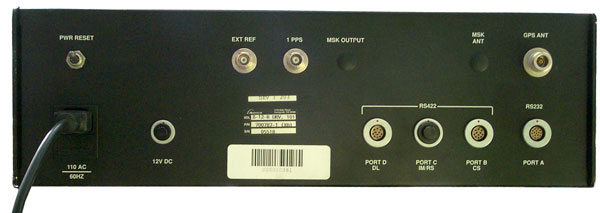
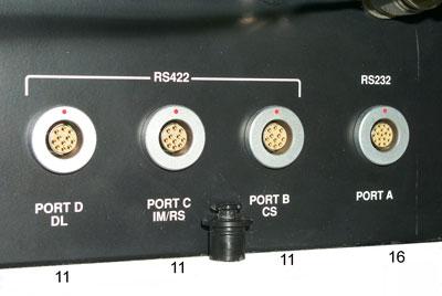
Connectors
Z12
They are fischer A086, 104 series. (
Plastic) (Metal)
# of
contacts
|
Contact
pin
Config
|
Interface
|
Metal
Plug
|
Contact
Block
|
Top
Shell
|
Bottom
Sheell
|
Ferrule
|
3
|
A040
|
U1
504-A
|
S 103
A040+ |
|
|
|
|
11
|
A056
|
U1
504-A |
S 104
A056+ |
|
|
|
|
16
|
A086
|
U1
504-A |
S 104
A086+ |
E21 504-A086-J (solder)
E21 504-A086-K
(crimp)
|
U31 504-A03 (blu)
U31 504-A04 (vio)
U31 504-A09 (trq)
|
U32 504-A03 (blu)
U32 504-A04 (vio)
U32 504-A09 (trq) |
U33 504/5.0
|
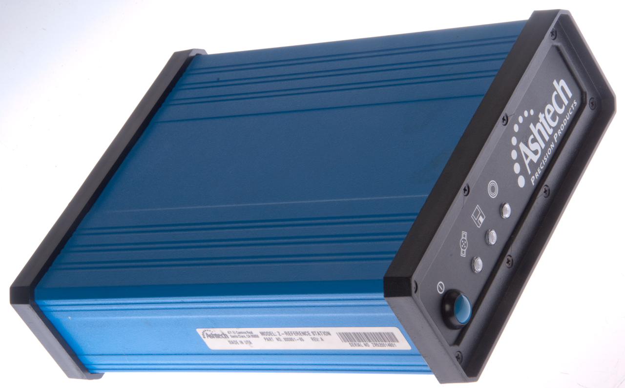
Z Reference
Post Processing
By recording precision data on the actual orbits of the GPS
satellites and using that data along with time stamped data from
a precision GPS receiver the data can be reduced to determine
the precise location of the GPS antenna used. This is a
version of Differential GPS (Wiki).
Z Reference
This GPS receiver includes an input for an external
frequency reference, unlike the Z12 above. This might better
lend it to precision GPS work.
Photos
ZR Fig 1
|
ZR Fig 2
 |
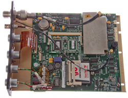
ZR Fig 3
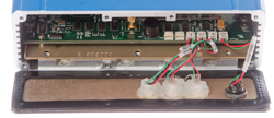 |
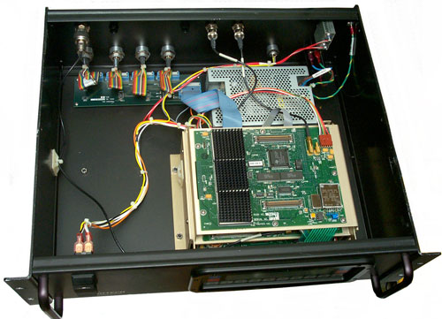
ZR Fig 4 Inside
Compact Flash drive: SanDisk 90 MB
Battery: TL-5/86 3.6V (unknown condition)
 |
Disassembly
Remove front panel (+) screws and hinge down the
panel.
NOTE: Be very gentle pulling off the connectors after
noting which goes where (mine were marked I, II,X and O, but the
X socket came off the PCB and needs to be soldered back down.
O: switch
X: circle light
II: Satellite light
I: Drive light
Remove the three hex head screws using a 3/32" ball end hex
wrench.
Remove the back panel (+) screws and slide the PCB and rear
panel assembly out the back.
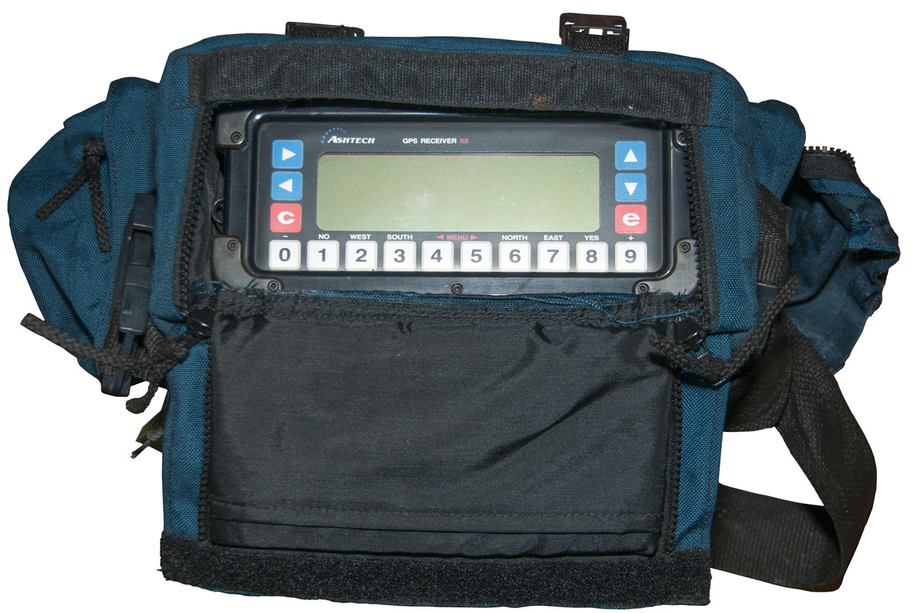
Operation
Ranger
This GPS receiver has the look and feel of the rack mount Z12,
but much smaller. If you compare this receiver to the one
at the top of the page, it's the same size as the main part and
has an identical front panel. But the rear panel uses
different connectors than the above receiver and different from
the field version Z12 shown in the Z12.pdf manual.
8 Feb 2017 - added
Photos
Fig 1 Carry Bag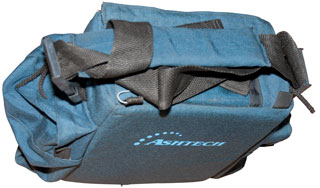
|
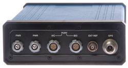
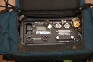
Fig 2 Front panel with Z12 look and feel
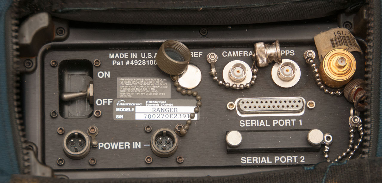
 |
Fig 3 Field connectors different than rack
unit.
Power In dust cap: Amphenol 97-60-10
Power Cable connector: 3106A10SL-3S
Power Voltage: TBD
 |
|
|
|
Power Connectors
To make power cable use: 3106A10SL-3S.
The two power connectors both have pin-B as chassis ground, but
pins A and C are not interconnected on them.
This implies that the idea is to have two independent power
sources so that one can be changed while the other provides
continuous power. For that to work there needs to be diode
isolation so the dead battery does not drain the good
battery. The ZY-12 supplemental manual has the pin out
table.
Pin
|
Function
|
A
|
+10 to 32 VDC
|
B
|
Chassis Gnd
|
C
|
-10 to 32 VDC
|
Guess input as 9 to 32 VDC.
Operation
Modes:
Z mode: A - receiver reverts to Z mode when A/S is detected, Y -
always in Z mode, N - never Z mode.
Ranger mode: 0 - geodetic mode: stores phase data in B-files for
post processing, 1- Stores phase data in B-files for post
processing in code phase only, 2 - stores smoothed positions in
C-files only, used for real time differential corrections (no
post processing).
This receiver can be used to receive Y code if it is
keyed. The manual describes how to do this with a KYK-13 and unspecified
"interface box".
Screens:
Screen
|
|
0
|
Sky Search
|
1
|
Orbits
|
2
|
Navigation
|
3
|
Tracking
|
4
|
Mode
|
5
|
Differential
|
6
|
Waypoint
|
7
|
Satellite Selection
|
8
|
System Control
|
9
|
Site & Session Control
|
10
|
All-in-View
|
11
|
Visibility
|
12
|
Bar Code Control
|
Related
Ashtech GPS receivers
4GPS 4 Way power splitter for GPS
CSI LGBX Pro DGPS Receiver
GPSpat GPS & Satellite Navigation
Patents
HNV600 Rockwell Trooper GPS HNV-600
& HNV-960
HP Z3805A Time & Frequency GPS Receiver
Jackson Labs - LTE-Lite GPSDO
Evaluation Kit
KS-24361 (Lucent ) HP/Symmetricom
Z3809A, Z3810A, Z3811A, Z3812A GPSDO System
Magellan GPS Commander
Magnavox MX7221 GPS Receiver
Motorola GPS Receivers
MX4102 MX 4102 Transit Satellite
Navigator & MX 4200
Differential GPS receiver
Northern Telecon GPS Satellite
Simulator STR2760 -
PLGR PLGR GPS Family
PLGR-II Rockwell HNV-2000 PLGR II SPGR GPS
Receiver
PSN-6 R-1897/PSN-6 Loran Receiver
PSN-8 PSN-8 GPS receiver
PSN-9 GPS receiver
PSN-10 SLGR GPS receiver
PSN-11 PLGR GPS receiver
PSN-13 DAGR GPS receiver
Q5200 Quantic Q-5200/SM Timing GPS
Receiver
Rockwell Trooper GPS HNV-600
Rockwell HNV-2000 PLGR II SPGR GPS
Receiver
5001A Stanford Telecom 5001A Navstar Test
Transmitter
ThunderBolt Trimble GPS Timing
receiver
Trimpack Trimble Trimpack Family of
GPS receivers
URN502 URN-502 Vehicle Mount GPS
Receiver System
Z3805A Time & Frequency GPS Receiver
Links
Back to Brooke's Products
for
Sale, Navigation, GPS, Military
Information, Home
page created 19 May 2009