Shortened Antennas for Portables
by Dennis Starks
Part I, Lowband Shorties
Forward
The Problems
Early Commercial/Military
Solutions
My Own Early Attempts
True Rubber Duckie's for HT's
Part II, Do You Really Need Nine Feet?
Forward
Supplies
The PRC-10, PRC-25, etc.
PRC-70
PRC-108
Part III, Resonant Antennas For HF Portables
Forward
Short HF Reasonant Whip
Antennas
Other Load Coil Ideas
Some Mast Ideas
AT-271 Mast Preparation
Other Mast Ideas
Adjustments & Mounts
Part IV, HF Antenna Applications
Forward
Applications
The
PRC-74
The
PRC-47
Semi-Fixed
Station/Mobile
Use
Webster
Band
Spanners
The
PRC-74's AS-1887
Conclusion
SOURCES; Lowband & PRC-127 Rubber Duckies
PS I haven't edited the spelling.
Part I, Lowband Shorties
Forward
Quite a number of people
in the past have asked me about the rubber duckie antennas I use on
my lowband portables. While it would have been a simple task to just
give you all the contact information of a company, and model number
of the particular antenna I use (see the "Sources" column below),
Some explanation was required as to why this was the only lowband
VHF rubber duckie antenna available that would work. The explanation
kept getting longer, and longer, till I had the makings of a series
of articles. I thought I'd give you all the back ground information
first so that you do not repeat the mistakes that I made. So begins
the tale of my early quest for an antenna of manageable length yet
reasonably efficient for my portable lowband radios.
The Problems
Years ago I began a
search for a suitable rubber duckie type antenna to use on my
lowband portables. I went to all the big name commercial suppliers
of these type products and found that they either offered nothing,
or that what they did offer was custom tailored for use on a
specific model of radio and unusable on any other. The few generic
antennas that did exist would not work regardless of their quality
or design because of several variables that could not be compensated
for by the manufacturer even if these were custom made to order
(which they were).
The most critical of
these variables was radiation efficiency, frequency of operation,
the real-world effects of the radio's own physical packaging, or
electronic design, and all these combined with the extremely
narrow band width that could be expected from an antenna that
would be reduced in size to this great degree.
To explain, any
shortened antenna will suffer a reduction in band width regardless
of how much it has been shorted, the method used, or it's
frequency of operation. These truths combined result in an
extremely narrow window for operation of an antenna that has been
reduced in size from a factor of about 5 to 1. So if you build an
antenna to be resonant at 51 MHz in free space, or with a
substitute counterpoise (radio case) it's resonance will change
when it's actually installed on the radio. Being off
resonance even slightly at these frequencies will result in
drastically reduced radiation efficiency. When you combine this
poor efficiency with the typically low power found on these type
radios the result is a pretty much useless radio system.
Early Commercial/Military Solutions
To compound the above
problem, the manufactures of commercial lowband portable
transceivers, as well as the military, very seldom used an antenna
that was actually resonant at it's frequency of operation. Most
often they used the same industry standard 1/4 wave telescoping
antenna that was used on high band VHF (140-175mc) combined with a
fixed internal load coil (usually a toriod). This coil too had a
very narrow bandwidth & a large selection of different values
were needed to attempt an approximation of the radio's operating
frequency. I should note here that this particular arrangement was
so poor as to make these radios completely useless.
The military's
equipment used a similar short antenna/load coil system as
commercial industry however they greatly improved on efficiency by
making the load coil variable. Hence the antenna system could be
adjusted to produce the best possible resonance. This is how it's
done on such radios as the PRR-9, PRT-4, PRC-6, CPRC-26, even the
PRC-68 [a side note, any of these radios will load a standard 2
mtr rubber duckie as their original antenna is nearly resonant at
2 mtrs]. In later years some commercial radio companies would
follow the military's lead and replace their fixed load coils with
variable ones. Though the antenna length was greatly reduced (over
a full size 1/4 wave), and radiation efficiency increased,
antennas were still too long & fragile to be of practical use
while portable.
All these differing
methods just confounded the efforts of the after market suppliers
of antennas to try and produce a product that was useable among
all these variables. Then we add to the dilemma the dozens of
different antenna connection/mounting types, and the fact that not
even one manufacturer could standardize on an antenna system in
it's own product line. Motorola for instance started out with the
simple high band 1/4 wave telescoping antenna & the fixed
internal load coil on it's HT-200. They then went to a rubber
helical type that was nearly 2 feet long on it's MH-70 (supposedly
resonant). The more resent MT-500 used a rubber helical that was
almost 1.5 ft long. These too used an internal coil to attempt
resonance. As these last two attempts moved more of the radiating
hardware to the outside of the radio they were an improvement, but
they still suffered from efficiency problems associated with the
fact that they could not be precisely turned to the operating
frequency unless they were installed on the radio at the factory.
My Own Early Attempts
The effort began trying
to outfit such radios as old GE & Motorola "Draggie Talkies",
the Hallicrafters OPS/FM-2 & FM-7's, even an old PRC-10. All,
save the FM-2, and of course the PRC-10, were lunch box portable
types. As these were designed to operate into a 50 ohm load, and did
not suffer from internal load coils designed to make a totally
unsuitable antenna work, all that was needed was a resonant antenna
short enough to allow me to carry it through my front door without
getting flipped over backwards. In the early days of our county's
Emergency Management Agency (called Civil Defense back then) we used
these radios as well as a few PRC-25's for bootlegging on 49.9 MHz.
All these radios had come to us by way of various federal agencies
for free. But typically none had all the necessary ancillary
equipment needed to put them in service. Neither did our small
agency have the required funds to purchase those ancillaries.
My first attempts to
provide an efficient shortened antenna for use on these Lowband
portables centered around making modifications to existing
antennas. Usually old defunct CB radio varieties intended for
vehicular use. They could be found at garage sales & flea
markets for as little as a few cents, or even free. Of these, the
all around best to work with were the short center loaded types.
They offered several advantages over other designs which included
smaller physical size & tough construction, better efficiency,
slightly broader band width, & most important, ease of
modification. The finished products in every case would greatly
surpass the performance of the radio's own original equipment, or
any after market/commercial antennas that were available.
Of the center loaded
CB antennas, the best by far were those produced by
Hygain/Hustler. They came in lengths from a 1.5 ft (Mini Twin
Truckers), to around 4 ft. The heat shrink tubing could be easily
removed from the load coil allowing for modification & easy
replacement. And of the utmost importance, they all had what every
commercial antenna lacked, that adjustable component needed to
compensate for all those variables noted above. This by virtue of
a set screw adjustable resonator (stinger for you CBers) so they
could be put exactly on frequency regardless of the physical
packaging of the radio they'd be used with.
The modifications
could be very simple, or as complex as I deemed necessary.
Sometimes I needed only to removing about 1/2 of the windings from
the antenna's original load coil, then using a field strength
meter to adjust it's resonator for maximum radiation. Other times
elaborate mounting methods were explored, or the basic antenna was
further shortened to a much smaller size than originally intended
(for use on HT's). And believe it or not, in some cases no
modifications were needed at all (details in Part II).
Some sort of flex at
the antenna's base was always needed to absorb shock & prevent
damage to the antenna & radio. Sometimes we simply used the
spring that was originally affixed to the antenna. Other times we
modified the springs from other antennas to work, but the best
where those we made ourselves. Borrowing from the military's
design that had been in use ever sense WW-II, we often stole the
flexible goose neck type hardware from old desk lamps, cut it up,
and fashioned the needed fixtures to approximate the effectiveness
of the goose neck antenna bases used on the BC-1000, PRC-10, &
PRC-25/77. It looked & worked Great!
Antennas as short as 1
ft were made for use on larger HT's like the FM-2 (slightly
smaller than a BC-611), and as long as
2-3 ft for use on the GE & Motorola Draggie Talkies.
Adjustment was simple, though a little more difficult than setting
up a vehicular antenna where a SWR meter could be used. When
making an antenna for use on a portable there is no way to make a
connection between the radio & the antenna for taking SWR
measurements that will not adversely affect the system's
resonance, or result in false readings caused by the extra
hardware that's been temporarily connected to the system (not to
inter into the SWR debate). So a field strength meter is the only
option.
To adjust the
antenna/radio combination, the radio with antenna affixed is
situated in a position free of obstructions that can be exactly
repeated. i.e. if you have a need to move the radio to make
modifications, you want to be able to put it back in exactly the
same place for the next check. A field strength meter is then
placed as far away as possible yet remaining visible from the
radio's location, it too must remain stationary so as to not mess
up repeated measurements. An FS meter built to accept either a
remote antenna, or external meter movement, is great for this
application as then the RF sensing portion of the meter can be
remotely located while the meter movement itself is setting next
to you.
The antenna's
resonator ("stinger", or whatever else is used to make fine
adjustments) is placed in the center of it's travel. Key down the
radio & take an initial reading on the FS meter. Move the
resonator to it's minimum & maximum settings taking FS
readings at each extreme. If the FS reading went up at the
resonator's maximum setting the antenna most like too short.
Likewise, if the FS reading went up at the resonators lowest
extreme then the antenna is most likely too long. In either case
spreading, and or compressing the turns in the load coil may get
you closer to your goal. If not, and your antenna was too long,
great, now begin removing windings one turn at a time until a max
FS reading is achieved. If you remove one too many turns simply
compensate with an adjustment of the resonator.
Another method that
would get the antenna in the ball park, or at least let you know
where it was basically resonant while saving some wear & tear
on your radio involves the use of a signal generator. Connect the
antenna to the signal generator & advance it's frequency while
watching the FS meter. When the max FS reading is found, simply
look at the Signal generator's frequency & you'll see where
the antenna is approximately resonant. Final adjustment of the
antenna must still be made on the radio it will be used with.
These same procedures
may also be used for bands other than 6 meters, and with other
antenna types. Base loaded, Top loaded, and fiberglass whips may
all be used in much the same way, but each suffers from it's own
draw back. Base loaded types while they are typically very damage
resistant tend to be slightly less efficient than the top or
center loaded breed. Additionally, only the very high quality
types will allow you to gain access to the load coil, even then
you may destroy it trying.
Fiberglass whips (usually top loaded) are very efficient, and do
allow modification but they are stiff as a board thus poorly
suited for use on most portables (they will however make great
mobile antennas). Center loaded antennas are generally very tough,
have good efficiency, and are the easiest to modify.
True Rubber Duckie's for HT's
While it is possible to
modify the Rubber duckie antennas that were built for the CB market,
and I have saved a bundle of them for this purpose, I've not yet had
a chance to do any experimenting with them. Most do already
have the appropriate thread for use on many commercial HT's. Aside
from purchasing a commercially available antenna (see "Sources"
column below) there are a couple options.
If you have an HT that
uses an internal load coil, you can use a duckie that was intended
for use on 2 meters (or the high band VHF spectrum). This is
because most early HT's had an original antenna that was actually
intended for use at these frequencies (telescoping 1/4 wave). You
may have only one obstacle however. The internal load coil may not
be suitable, and if it's the fixed type, you can bet it's not
(especially if you have changed the radio's original frequency).
If you have an adjustable internal load coil, you need go no
further, this will tune about any type antenna you screw to the
radio. It will not however be as effective as one that is actually
resonant. In fact, it will be just a little better than keying
into a light bulb. Compare the effectiveness of the PRC-68 when
it's 6" antenna is used (advertised 300 yard range which is
actually closer to 100 yards), and it's longer rubber helical
(about 1.5 ft) with it's approx 1 mile range (usually a little
better).
If your HT has a fixed
internal load coil you still have an option. You can replace this
fixed load coil with an adjustable one. An original coil may still
be available from the manufacturer (many producers of lowband HT's
replaced the fixed coil with an adjustable one towards the end of
production). Alternately I have robbed the coils from old 49 MHz
radios and used them in my HT's combined with a rubber duckie
antenna similar to those used on the PRC-127 (see "Sources" column
below). It worked reasonably will.
But of the options
available, the best is an antenna that is actually resonant at the
frequency in use. For instance, the internal load coil/PRC-127
combo noted above worked well up to about one mile (talking to a
like radio). When the internal load coil was removed, and a
resonant 10" commercial antenna was installed, this range was more
than doubled.
To close, when you see
those old CB antennas at garage sales, flea markets, Hamfest etc,
don't stick your nose up at them. If they are cheep, buy um! Every
part of it regardless of it's size will someday be useful. And the
older it is, the better. And if your lucky, each hamfest might
yield a bundle or two of them in the dumpsters at the end of the
fest. There is only one exception, stay away from all the Oriental
imports! They are all, without exception, JUNK! All my 2, 6, &
10 meter antennas are made from old junk CB antennas (base,
mobile, and portable), as well as some expedient antennas for my
PRC-25, -47, -70, & -74, but
those are another story.
SHORTENED ANTENNAS FOR PORTABLES; Part II
Part II, Do You Really Need Nine Feet?
Forward
How many of you are not
fortunate enough to have the original whip antenna for your PRC-74?
I'd say most of you as they are very scarce, in extremely high
demand, and damned expensive when you do find them. Are you one of
the lucky few to own a PRC-70? If so, how do you like carrying this
already monstrous radio around with the extra burden of a 9
ft whip? Heaven forbid your antenna should hit the
ever present tree limb or you'll be laying on you back like a
stranded turtle. The PRC-70 even needs this whip while operating on
6 meters! Ever need an antenna on your PRC-10, -25, or -77 that was
a little more efficient than the short tape antenna but not as
cumbersome as the long whip? Do you lack the original rubberized
spring base for your PRC-8, -9, -10, -70 or -74? Fear not, there are
cures for each of these ailments that will cost you very little and
at least get you by in a pinch, or until the real thing comes along.
Supplies
We military radio
affectionate's should be very grateful for two things, especially if
we are on a budget, wish to operate these rigs in the real world, or
can't find the original components needed. #1, Our government chose
to use standard threads on nearly all our military radios. #2, they
chose to use 9 foot as the standard whip antenna length for most of
our radios, HF & VHF alike.
By far the most common
connection used on our military radios to affix the portable whip
antenna is a front panel 3/8 x 24 threaded base/mount. 3/8 x
24 has been the industry standard thread for mobile antennas ever
sense an need for a portable/mobile antenna was first perceived
back in the 1930's. This universal thread is used on antennas for
every conceivable application to include Commercial, Ham, CB,
& Military, MF, HF & VHF alike. As a result, we have over
60 years worth of junk from hundreds of sources to obtain our
needed hardware.
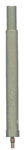 |
AB-591
As did the first military radio to use this thread
(the BC-1000), the PRC-10 family radios have a 3/8 x 24
front panel mount for the long whip antenna (combination
AB-129 antenna base/spring & AT-271
antenna). The PRC-25 family,
PRC-70 & many others use 3/8 x 24 threaded rubber
spring/bases (AB-591) and will accept the same antenna as
the PRC-10's(AT-271). The 9 foot length of the AT-271,
like the 3/8 x 24 thread, is also an industry standard.
Not only this, but it's also the length of a resonant 1/4
wave antenna on the 27 MHz Citizen's Band (CB).
Hence, we again have an abundance of available hardware to
choose from with a cost that will range from very cheep,
to free.
[Brooke's note: when you click on the AB-591 spring base
photo notice that there's a skinny finger below the
threads. It's there to activate a switch in the
PRC-25/PRC-77 (and other) radio telling the radio that a 3
meter (9') whip antenna is installed so the proper
matching circuit is selected (depending on if in the low
or hi band). My Tape Whip
Adapter allows using mil antennas on civilian
antenna bases. The TWA web page has a table of
antenna, base and radio thread sizes)]
|
The PRC-10, PRC-25,
etc.
This trick will work with
virtually any radio that was intended to use the AT-271 sectional whip, or any other similar
antenna of approximately 9 foot in length. Simply substitute the
AT-271 with a CB antenna of any type you wish that has a 3/8 x 24
thread. As a CB antenna is an electrical 9 feet regardless of it's
physical length, it will work! Suitable CB antennas range in
types from 1 to 9 foot fiberglass (continuos or top loaded), &
1-4 foot center loaded. [Note, 102 or 106 inches are the
factory supplied antenna lengths for the 11 mtr (26-27mc Citizen's
Band) dependent on spring use.]
With the PRC-25 class
radios (including the PRC-77, SEM-35
etc) you will realize an antenna system that while not nearly as
long as the standard AT-271 is still considerably more efficient
than the short tape antenna. For instance, I once used a
PRC-25 for a talk-in radio at an indoor hamfest. The short tape
antenna was good for little more than talking to the parking lot,
but the ceiling of the building was too low to allow the use of
the AT-271. A 4 foot center loaded CB antenna was substituted for
the AT-271 resulting in an antenna that was 4.5 feet long vice 9
ft, and an increase in range of over a mile over that of the tape
antenna.
 |
AB-129
Years ago, with
my first PRC-10, I had none of it's original accessories
excepting a handset. I didn't even have the AB-129 rubber
spring/base (itself a very useful item for various
applications)! A standard antenna spring was used as found
on many CB mobile mounts combined with a series of different
antennas lengths dependent on the application. i.e. a 2ft
center loaded antenna was used for short range/portable
work, and a 9 ft whip for stationary/longer range. All were
screwed into the same spring which was affixed to the
radio's long whip connection. It was all an excellent
alternative until the original antennas came along, and
still finds application today. |
PRC-70
Owners of the PRC-70
already know that an acceptable, and almost identical substitute for
it's original antenna is the AB-591/AT-271 combo as used for longer
range with the PRC-25 & -77 among others. They also know that this
is the shortest possible antenna that can be used with this radio
even when it's being operated on 6 meters. It's a real pain in the
ass to be forced to carry this already very cumbersome radio around,
but with the added impairment of a 9 ft antenna it becomes most
unbearable. And when your operating this set on 51 MHz, you really
become irritated!
But fear not! The fix
is very simple and may cost you absolutely nothing. Simply swap
the AT-271 for the CB antenna of your choice & desired length,
and it will work. Even on the HF bands! As the radio's automatic
antenna tuner was designed to work with an antenna of about 9 ft,
and as the CB antenna is an electrical 9 ft, the radio doesn't
know, or care if the antenna is actually only a couple feet long.
Some caution, and
common sense should be exercise however. While the radio may tune
a two foot antenna, it would not be wise to try and use it thusly
on 75 meters. In all cases it's advisable to use the longest
antenna that is practical for the application. Also, as it is
possible that the radio's tuner might see the antenna's load coil
as a trap instead of a resonant part of the antenna, it's probably
best to use an antenna that has it's load located as high up on
it's length as possible. What this means is if you try to
use a center loaded antenna, the tuner may only see the lower half
of this antenna (where the load begins) and try to tune this
portion alone. This may be as little as 1 ft or less on some
center loaded antennas. So it's best to use one of the top loaded
fiberglass types with this radio.
I've use a 3 ft top
loaded fiberglass antenna for use at 51 MHz to great effect. While
the radio did tune this same 3 ft antenna on the HF bands, it
would not be advisable to use anything less than 4ft (better 5 ft)
on the lower frequencies.
The PRC-108
The very same factors
that apply to the PRC-70 also apply to the PRC-108 and like HF
radios that use an non resonant 9 ft whip combined with an internal
(or external), manual (or automatic) antenna tuner. The PRC-108's
original antenna is the standard AT-271 whip affixed to a commercial
(CB type) stainless steel spring, which is in turn screwed on to a
bracket that mounts to the side of the radio. If you are not
fortunate enough to have this side mount bracket, you can fabricate
a resemblance of one if you are reasonably adept with hand tools.
Part III, Resonant Antennas For HF Portables
Forward
Unlike those radios noted
in Part II of this series some of our military and para-military
portables will require a resonant antenna. Of these the HF types
would seem to be the most problematic. Not so! We can have these on
the air in the portable mode with very nearly the same simplicity
and minimal expense as those types already outlined in this series.
For the most part,
resonant(or even non-resonant) whips for backpack portable use on
the HF bands do not exist on the commercial market, and only very
few(& prohibitively expensive) versions were produced for the
military. But a very nice one can be built, and as with most of
the hardware needed in this series of articles, your next local
hamfest will most likely yield everything you need. I'll begin
this part of the series with the construction details for a nearly
universal resonant whip antenna suitable for use on very wide
variety of HF portables. I'll close with just a few of it's
possible applications.
Short HF Reasonant Whip Antennas
Short whip antennas can
be very effective on the HF bands as has been proven over the years
by both the military, and the Ham community. In Vietnam part of the
test for qualification to operate the PRC-74 was to make a long
range contact with it's whip antenna. Many of these resulted in
satifactory links to Australia!
Hustler/Hygain
marketed a very popular HF mobile antenna system to hams for many
years. The system consisted of the same basic mast section
combined with a separate coil & resonator for the band of
choice. These load coils were/are available for all the ham bands
between 160(rather rare) and 10 meters, in both standard &
high power/heavy duty versions. For our purpose the standard
version is more desirable as we don't need the high power option,
it is lighter in weight, has a little less bulk, is far more
common, & is cheaper. Of the highest priority are the 75/80
& 40 meter coils, but if others surface and they are cheep,
get them too because if nothing else they'll provide the hardware
for other projects. Don't bother with the 15 or 10 meter
coils, they are pretty much
useless(except for the hardware).
Many of these coils
when found, especially the larger 75 & 160 meter versions,
will have cracked end caps, or loose threaded ends(where the mast
and resonator screw on), but that's ok this will just make them
even cheaper. This damage was most likely caused by harsh mobile
use, and is in almost every case is easily fixed with more than
ample strength for our application. All the metal used in these
coils in chrome plated brass, you need simply to take a Dremel
& grind away the chrome plating and effect the needed repairs
by soldering. Don't have a Dremel you say? SHAME ON YOU, buy
one! And a good supply of the high speed cut off disk. I
know for a fact that they(or a reasonable facsimile) are available
all over the world. I purchased my second one at a Woolworth store
in Malaga Spain, and my third one at a hobby shop in Naples Italy,
and my fourth one at the PX in Augsburg Germany.
The resonator(stinger)
used on the lower frequency versions of these coils is a bit stiff
for my liking(which accounts for the damage inflected on many of
them). Also the original base fitting dose not allow for much
travel/adjustment. The fix for this is easy & will allow the
antenna to be used in a wider variety of applications with less
probability of damage. The thread used for the fitting on this end
of the coil is also a standard used on nearly all US built
antennas, 1/4 x 20. You can simply replace the original
fitting, & resonator, with one removed from a common CB type
base loaded antenna(resonator cut to length with a Dremel or
grinder). Choose a fitting that is hollow clear through. To
allow greater adjustment/travel of the resonator take a 1/8" drill
bit and drill down through the center of the load coils top
fitting the full length of the drill bit(even into the plastic
form of the coil). This will allow several inches of possible
adjustment to the resonator(stainless steal 'stinger') rather than
the previously had 1".
Other Load Coil Ideas
Alternately a load coil
can be built completely from scrap using PVC fittings or the
hardware cannibalized from CB type center loaded antennas(those
called "Beer Cans" or "Cantennas" built by Antenna Specialist have
many usable parts for HF load coils). Suiteable enameled copper wire
can be canibilaized from old low voltage power transformers.
But winding these, and the possible variations are beyond the scope
of this article.
After you have
gathered the needed coils, and a suitable spring, the next step is
to construct a mast. The original Hustler/Hygain mast will work
but it's too long & heavy for convenient use. Besides, why buy
one when you can make a better one?. The options are endless, and
limited only by your imagination and skill with simple hand tools.
Some Mast Ideas
#1, Take a couple old CB type top loaded fiberglass
whips, strip one of it's heat shrink and wire(save the wire). Cut
it down to about a 2ft length(it's length is not significant &
can be just about anything you are comfortable with). Take the
second whip & remove it's 3/8 x 24 fitting(if you don't have a
supply already scavenged). Affix this fitting to the cut off end
of the 2ft mast you've already prepared. Connect the two ends of
the mast with a piece of the copper wire saved from the original
winding(most effective will be a slow winding with about 2 inches
or more between turns). Now recover your new mast section with
some heat shrink tubing which will most likely be your highest
investment in the entire project(aside from the Dremel I made you
buy).
#2, As has been noted, the AT-271 9ft long sectional antenna is
without exception the most common military antenna ever produced
(it's been in use for over 50 years). As a result there are many
around that have been damaged, some beyond practical repair.
Most of the damage to these antennas has been to the top few
sections which is perfect for us as we only require the bottom
two or so. The possible uses for these remaining bottom
sections, and the methods you may utilize them will again
present several options.(special note, the PRC-74's original
antenna is a modification of the AT-271 with the second mast
section being replaced by a band switched load coil)
Option 2a, If you
only wish to use the first section of the old AT-271 alone you
may simply run a 3/8 x 24 tap into it's end and insert a
standard threaded stud(usually used between a spring &
antenna mount). If you don't have a 3/8 x 24 tap, or a
threaded stud, and don't wish to buy either, you may proceed to
Option 2b and make them yourself.(While one section of the
AT-271 will work, I recommend using both of the first two
sections)
Option 2b, If you
wish to use two sections of the old AT-271, or one of the
alternate mast ideas below, you must make the needed fitting
that will allow mounting of the load coil to the top of AT-271
section. Or, if one of the other mast ideas are used, two
fittings will be needed(one for each end).
What we want is a stud
with about 1/2 inch of threads to mate with the load coil(or
spring/base), and 3/4 to 1 inch of shank to fit the mast section.
The diameter of this shank portion is dependant on the mast section
you wish to use & the method by which you wish to attach it.
Your preference may be a simple & 'permanent' force fit
requiring a few mild whacks with a mallet and no further work. This
will work just fine for any mast section type you use, and might
even be preferred for the last mast section options outline below.
But for the AT-271 modification, you may opt for the 'serviceable'
method which will require a snug fit of the fitting combined with a
small roll pin for final attachment, this method will allow you to
service your antenna in the event you damage it in the future.
Either will work just fine it's all up to you.
Our efforts are again
made simpler by the military's choice of threads as 3/8 x 24 is
not only an industry standard for antennas, but it is also a
standard SAE thread(often called 3/8" fine). You'll need to go to
your local hardware store and purchase a 3/8 x 24 bolt that's made
from as soft a material as possible(brass would be best, aluminum
nice, mild steel will work). The bolt should have an unthreaded
shank(portion between the bolt's head & the threads) of at
least 1.5". While your at the hardware store also buy a matching
nut of hardened steel.
The first step is to
cut off the bolt's head taking care to save as much of the
unthreaded shank as possible. Then chuck the bolt(shank first)
into your Poorboy's Lathe(power hand drill). Screw the nut down
firmly on the bolt as far as it will go. This nut will serve the
multiple purpose of premeasuring & protecting the half inch of
threads you need to keep intact, and help in the next two steps.
The bolt with it's
head removed is now chucked in your drill shank first, and a nut
is screwed down on it as far as it will go. With the drill
running, hold a hack saw blade against the threaded portion of the
bolt to be removed using the nut as a fence(reciprocate the blade
slowly to keep it's teeth clear of shavings). Once you've cut off
the unneeded portion of the threads, remove the nut. This may
alone clean up the ragged edge of the cut threads well enough to
allow use. If not, clean them up with a couple touches of a fine
file(again while the drill is running).
The next step is to
turn down the shank of the bolt to fit the mast section. First put
the nut back on the bolt(it will prevent you from messing up the
threads & provide a guide for the turning process). Then
loosen the chuck and reposition the bolt so as to leave about 1
inch between the face of the nut & the drill's chuck. With the
drill running, use a file, just as you previously did with the
hack saw blade, to turn down this 1" portion of the bolt to the
size needed to fit the mast section. Once you have the bolt turned
down to the desired size, remove the nut(remove it now or you may
be sorry!). The last step is to cut off the unwanted portion of
the bolt using the hack saw blade just as you already did with the
threads.
Your fitting should
now be pretty much finished, but if you screwed up, that's ok, we
can fix it. If you didn't get the fitting turned down enough, you
can put it back in the drill threads first and turn it down some
more, but take care as you'll not have much left for the chuck to
grasp & you may mess up the threads. If you turned the fitting
down too much you have two options(DO NOT crush the end of the
mast section!). First is to use a old Gun Smiths trick, with
a center punch 'stipple' the shank of the fitting(make a bunch of
little dents in it). Each little dent creates a tiny crater with
swelled edges effectively enlarging the diameter of the shank. If
the shank is still too small for this trick to work, you can shim
it with a strand or two of fine copper wire.
[Note the TWA2 Antenna Adapter
has 5/16-24 female threads to accept the military antennas &
AB-591 and 3/8-24 male threads to mate with common ham and CB
antenna bases.]
AT-271 Mast Preparation
If you are using the
first two sections of the AT-271(as you should be) they will no
longer be held together while erected with it's internal spring
tension. If your wish to retain this feature skip this paragraph
& go on to the next. If you do not wish to use the antenna's
internal spring you'll need to provide a tighter fit between the two
mast sections. This can be done by stippling the end of the second
mast section with your center punch(not too much as you still want
to be able to take it apart for storage).
To restore the
internal spring tension feature of the AT-271 all you'll need is a
small role pin obtained from your local hardware or automotive
parts store, & a drill bit to fit it(a small brass or mild
steel pin will also work).
Step #1, Drill a hole about 1.5" from the top end of the
#2 mast section just large enough to fit the role pin. This hole
will be in the brass section of the mast but far enough from the
end to still allow insertion of the 3/8 x 24 fitting without
interference.
Step #2, Fashion a small wire loop. The loop should be large
enough to freely accept the role pin, yet small enough to still
pass through the
trunk of the #2 mast section.
Step #3, Measure the needed length of the string that's
attached to the internal spring of the #1 mast section. This
will be about 2-3" shorter than the distance between the role
pin hole in the #2 mast section and it's bottom end. Tie the end
of the string to the small loop you have made.
Step #4, Prepare a 2ft length of stiff small gage wire(the wire
from a wire welder 'Mig' will be perfect). Fashion a VERY SMALL
hook in the end of the wire. Insert the 'fish wire' through the
trunk of the #2 mast section (bottom to top)leaving about 1" of
the hook end exposed. Now hook the wire loop of the string and
pull it through the #2 section stopping just at the hole you've
drilled for the roll pin. Insert the roll pin through it's
drilled hole, and the string's wire loop(still being held by the
fish wire). You can now unhook the 'fish wire'(best done by
simply pushing it back down through the mast section the same
way it came in).
Step #5, Place the end of the roll pin against a hard surface
and give it's other end a tap or two with your center much. The
idea is to flare the end if the role pin just enough that it
will not readily pass through it's hole. Push the flared end of
the role pin in to where it just contacts the hole. With your
Dremel, cut off the excess roll pin on the other side, then
flare this end.
Step #6, the 3/8 x 24 fitting you've made can now be installed
on the mast you've just finished. If you can never foresee a
need to remove the fitting it can be affixed as noted above. If
you wish to be able to remove it in the event of future repairs
or modification, you can attach it with a role pin. If this is
the case, insert the fitting into the mast and drill through
them both at the same time. Your center punch, and Dremel will
complete the process just as above. But don't flare the ends of
the roll pin too much, if you have a good snug fit you may not
need to flare it at all.
Other Mast Ideas
|
M-422
The
possibilities are endless! I've used MS & AB mast
sections as used on the RC-292,
and AB-15 antenna systems. Fittings & adapters can be
easily made from the ends of the many damaged sections that
can be found*. These will allow elevated use of your basic
antenna while operating in the semifixed station mode. They
will also allow the use of your load coil alone on host of
standard military vehicular antenna mounts. A special
caution is needed on these type of mast sections. NEVER use
anything but your hands to assemble them. NO PLIERS! Always
use a silicone based grease on the threads before assembly.
If you do not heed these warnings you will have a permanent
whip antenna system as you will not be able to get them
appart. *[Fair Radio also
stocks an M-422 adapter ( Stock # 2A168-422) that goes
from the male end of these mast sections to a male 3/8 x 24
stud. A military item, it was designed to allow the use of
standard AB & MS mast sections as an expediant
replacement for the AT-271]
Aluminum
sections can be easily made useing the same basic 3/8 x 24
fitting construction details as explained above, and
tubing robbed from old base Ham or CB antennas.
A very
attractive option is to use automotive steel break line.
This is readily available from all automotive parts stores
in various lengths & diameters. Just fabricate 2 of
the 3/8 x 24 fittings as outline above for a tight force
fit with a mallet into each end of the tubing. Covering
the completed mast section with some dark colored heat
shrink tubing will give an extremely professional
appearance & may prevent you from getting the crap
knocked out of you via an RF shock.
|
Adjustments & Mounts
You might be surprised to
know that the antenna you've just fashioned is almost the exact
equipment used on a number of Para-Military HF Packsets. Some
of which are listed below.
Basic adjustment of
this antenna can be carried out with an FS meter in the same
fashion as outlined previously in this series. If the radio to be
used has an internal antenna tuner(like the PRC-74) you may not
need to adjust the antenna at all. Just having it in the ball park
will be fine because if your using a radio capable of multiple
frequencies(even if they are located in the same band) you will
quickly exceed the antenna's narrow bandwidth. But if you do wish
to align the antenna for peek performance, you should first load
the radio into a fixed 50 ohm load before attaching & aligning
the whip.
If you will be using a
radio that does not have an internal tuner, you will need to get
the antenna as close to the operating frequency as possible. There
were many HF backpack sets that while they had provision for use
with a whip antenna, had no externally accessible means of
adjusting it. Some used a primitive external antenna tuner that
was a part of the antenna's mount apparatus to fine tune the
system. Some of these included the Hallicrafters/OPS TR-9, SBT-18,
SBT-20 etc, Motorola SA-200 series, Galaxy Comm-2, and a host of
early SGC, Racal, Stoner & Spilsbury Products. A simple tapped
coil(toroid) & some adjustable capacitance would probably fill
the bill, and it's size could be kept to a minimum.
Mounts for all these
type radios were simple, and generally included variations on the
same few themes. Some used the hasp type fasteners found on all
military portables sense WW-II(like what holds the case halves of
a PRC-6 together, or an RT-70 to it's
AM-65). Others use studs that are similar to those used on mics to
hang them up on the dash of your car etc. And some used fasteners
similar to those that hold the tube covers on aircraft command
sets. In nearly every case, the needed hardware can be found in a
well stocked junk box(or in my case, Junk Warehouse #1, #2, or
#3).
Part IV, HF Antenna Applications
Forward
This last part of the
series will deal with a few specific radio applications for the
portable HF whip of Part III. Some ideas for it's use in a
semi-fixed station and/or vehiclular role will be presented, and
some possible variations on this same theme (Webster Band Spanner,
& the PRC-74's AS-1887).
Applications
The PRC-74
The most common HF
portable in our arsenal that needs a resonant antenna is the PRC-74.
And it's a good bet that if you own one of these radios, you do not
own the proper center loaded/band switched antenna for it. If you
do, it's another good bet that it cost you a premium! While a
substitute will not be as simple as those outlined in Part II, you
can still get the set on the air while awaiting the appearance of
the proper antenna(and required funds).
The original rubber
spring/base for the PRC-74 is identical to the one used on the
PRC-10 family radios (AB-129) which is far more common. The only
difference is that the spring for the 74 has a wire screwed to
it's base to allow connection to the radio's antenna binding post.
You can simply make the needed jumper by soldering a 3/8" lug to
the end of a piece of wire which is then secured by screwing the
AB-129 down on top of it.
If you do not have the
original side mount antenna bracket you can make one without too
much trouble. You'll need some sheet metal (aluminum, or mild
steel) and a couple hasp fasteners robbed from a 40-50's vintage
military radio. Try to use those as supplied on the RT-70, late
BC-1000 etc as they use dual external springs which will yeild a
little move travel, and are not quite as critical about where you
locate their matching hooks.
Your side mount will
be made in two pieces that should over lap about 1/2" when in
place. Take note of the variant PRC-74 you have! 2-12mc versions
are about 1 inch shorter than 2-18mc versions. Hence you want to
make the two pieces of the side plate longer that is needed for
the 2-18mc version (PRC-74B) so that it may still be used on an
earlier PRC-74. The hasp fastener is screwed to the lower
half of the mount bracket, and it's hook is attached to the upper.
Multiple screw/mount holes for the hook will allow use of the
finished mount on various versions of the PRC-74 (& other
radios). When cinched down, the hasp fastener squeezes the
two sections of the mount together, each end of which is hooked
over the edge of the top & bottom of the radio. Several
Para-Military radios use a similar method for the mounting of
their whip antennas.
The PRC-47
The PRC-47 uses a standard 3/8 (coarse) thread
on it's antenna insulator. All that will be needed to use your
whip is an adapter to allow attachment between the two different
threads. This can be made using a number of different methods, one
of which might include the modification of a spring by re-tapping
it's base & making a threaded stud from a bolt. The
easiest fix would be to make a fitting as previously outlined except
this time use a 3/8 (coarse) bolt & turn it down to mate with a
3/8 (fine) antenna fitting(female all thread) as robber from your
supply of old CB antenna junk. The PRC-47 will use the same
tune up procedure with this whip as is used for operation into a 50
ohm load. It should be every bit as effective with this shorter
antenna as it would be it's normal non-resonant 15ft whip (it's
minimum usuable whip length). The advantage will of coarse be the
minimal length of the antenna which will allow operation under
usually prohibitive conditions. (I should some time tell you all
about my operation of a 47 at a hamfest that was held inside a
National Guard Armory, and the 47's effects on the internal security
equipment of the building.)
Semi-Fixed Station/Mobile Use
Regardless of the mast
section option you used, your whip antenna (or it's load coil alone)
may find expanded application as a semi-fixed or mobile antenna. If
in the mobile mode, you need only the mast section you've already
made, combined with a suitable vehicular antenna mount. I do not
recommend this as a permanent installation, or if your vehicle will
be expected to travel where there will be overhead obstructions that
may damage the antenna. But as an expedient antenna needed for a
quick vacation trip down the highway, it will work great.
The antenna will
really shine as a Semi-Fixed Station antenna where you will be
operating while stationary for a relatively short period of time,
and possibly a little more range is desirable. The distance
between the mount device and the base of the load coil will have
little effect on the resonant frequency of the antenna. I/E, you
can have a mast that's 2ft long for backpack use, or 2-4 ft for
moving/vehicular use, or one that's 10ft or more for fixed station
use, with very little or no effect on the resonant frequency of
the antenna.
The above will hold
true until the length of the mast itself, or the combined physical
length of the mast & coil, approach the resonant length of the
frequency in use. For instance, if your operating on 10 meters
where about 8 ft is resonant, you can't use a length of mast that
could itself stand alone as an antenna then top that with a load
coil/resonator which is also resonant. In this case you'd end up
with an end feed 1/2 wave antenna which would present a very high
impedance.
If you have opted to
make adapters that will allow the connection of your load coil to
standard military MS/AB type mast sections, your in business! You
can stack as many of these mast sections as you feel comfortable
with, with your load coil at their top. The vehicular mount may be
the super common AB-15, or the AB-652 (better for longer HF
antennas). Elevated operation might even be had using the
components of the RC-292. Even standard
civilian ball & spring mounts can be used if you've purchased
one of the military adapters (or made one of your own).
I have used this
system at many a hamfest on such radio's as the GRC-9, PRC-47,
PRC-74, PRC-70, Syncal 30, even a few converted HF/AM 20 watt
marine radios. Today I keep a bundle of these mast sections in my
Old Power Wagon just for this purpose. One of my first mobile
experiences with a GRC-9 was checking in on the 75 mtr East Coast
Military Radio Users Net with it mounted in the back of my old
Chevy van. The antenna was an 50's vintage Webster Band Spanner
(more on it later) being elevated 6 ft (2ea MS mast sections),
secured by an AB-652 base. From southern Missouri (I was parked in
a friend's front yard) to the east coast on a 5 watt AM radio
operating into an antenna that had a total length of about 12ft,
it was GREAT!
Webster Band Spanners
A note on those old
Webster Band Spanners, mine came from a very dear friend who was a
retired Collins engineer (Bob Boller, N0RB). As he told the story,
this particular Webster had been included as factory equipment with
a Collins commercial mobile HF/SSB transceiver (30M1 I believe). Bob
had been trying to use the Webster for years on his boat &
camper with little success. But he'd been trying to use the antenna
as it was originally intended, just screwed directly into a standard
mobile ball mount, and it's true, they do not perform well like
this.
I should explain the
design of these old Webster antennas before proceeding, they are
basically a very long hollow load coil, about 3ft long with a 1
inch diameter (dependant on the particular model). It had an even
longer, very stiff resonator(stainless steel whip). Band/frequency
changes were effected by sliding this whip up/down the entire
length of the hollow load coil wherein it made internal contact to
the windings of the coil. Thusly the antenna could be tuned
for operation between 2 & 30mc(dependant on the model).
Bob's problem lay in that he
was trying to use the antenna as it was intended, as a base loaded
antenna that just had an unusually long base load. As we know,
base loaded antennas are not very efficient. My solution was
simple, use it as a center loaded antenna! Simply inserting
as little as 1.5ft of mast between the bottom of the Webster and
the mount transformed it from a poor base loaded dummy load into a
fabulous center loaded performer. When Bob saw the transformation
of that old antenna he'd been playing with for all those years he
tried to shame me into giving it back. I still have it after
almost 20 years!
Though long out of
production these old Websters can still be found with some
regularity at Hamfest today. If you find one, it's cost will run
from between $40 - $180 depending totally on the seller. Before
making a purchase, inspect the antenna closely as they had a few
minor failings that if combined with owner neglect or stupidity
might yield an impressive looking piece of junk.
As noted, the Band
Spanners have a very long & hollow load coil made from
fiberglass. This when combined with a stainless steel resonator
(with an unusually large diameter), resulted in an extremely stiff
antenna. If the antenna had been used mobile without a spring, or
with a spring that was too stiff, they could be easily broken (as
many of them are). Also, as this load coil is hollow it could fill
with water, and if left on the vehicle in the winter, it would
surely freeze & bust (without exception). So before
purchasing a Webster, closely inspect it for signs of
cracks. As the coil is imbedded in the fiberglass even the
slightest of hair line cracks could render it useless. Though a
very good performer when used as outlined above, the Band Spanners
are a very poor choice for any kind of
permanent installation. So be careful, they are too good to tear
up!
The PRC-74's AS-1887
If you are the lucky
owner of an AS-1887 it too can be use in many applications with, or
without, it's PRC-74. The AS-1887 can be directly substituted for
either the Hustler/Hygain coils, or the Webster Band Spanner, and
used in exactly the same ways(Portable, Mobile, Elevated, &
Semi-Fixed). But as with the Webster's, it's too good (&
expensive/hard to find) to tear up. So please heed some simple
cautions, and use some common sense.
This antenna was
intended for use with a low power radio. I would not be
comfortable trying to use it with any radio capable of more than
20 watts. While it will work very well as a vehicular antenna,
just as with the Webster it will not take physical abuse or
constant exposure to the elements. So use it with some common
sense, then take it down & put it away for the next time.
You will not be able
to precisely adjust the AS-1887 for a specific frequency like you
can the Hygain/Hustler or Webster. So either a simple/small tuner
will be needed, or a radio that has this feature built in.
Conclusion
My purpose with this
series was to present several options, & methods, for getting
your equipment on the air, with, or without, the proper ancillary
items. In doing so you may have noticed a couple of trends in the
design concept of military radios, and in particular those that are
operable over an extended frequency range. These concepts will hold
true whether the radio being observed is of HF or VHF, vehicular or
portable, type.
The length of non-resonant type antennas, usually 'are'
resonant at the upper extreme of the radio's frequency range.
This is done so as to allow a tuning device (either internal or
external) to load this same antenna/length at frequencies
'lower' than the actual resonant frequency of the antenna.The
short tape antenna of the PRC-25 & -77 are nearly resonant
at the upper end of their frequency range. At lower frequencies
the radio provides internal base loading. The same is true of
the PRC-8 (20-27mc) and the AT-271. [Note, the PRC-8 is of the
PRC-10 family radios which were the first to use the AT-271
antenna with this designation number].
- When the above is not true, then a particular antenna &
length combination was chosen as it was a pre-existing form.
Compare the civilian use of a standard 1/4 wave highband/VHF
telescoping antenna on lowband/VHF radios combined with an
internal load coil to make it work. Other examples include the
PRC-70, PRC-104, & PRC-108's use
of the AT-271. Had this style of antenna not been used on the
WW-II BC-1000, it would never have seen service on these radios
either.
And why the AT-271
antenna & 9 feet you ask? In the early days of portable
communications, & radios with tube type design, internal
space, and physical size & weight were of major concern. It
was easier to couple the high impedance of a vacuum tube to a
likewise high impedance thus reducing parts count, size &
weight. A 1/2 wave end fed antenna has a very high impedance
(several K ohms). Hence it was nearly possible to connect the whip
antenna directly to the plate of the radio's output tube. This is
indeed what was done on such radios as the BC-222 & BC-322
(our very first "Walkie Talkies"). The AT-271 family antennas
presented an approximate 1/2 wave at the frequencies the BC-1000
worked at. Ever wonder why such a tiny radio as the BC-222 needed
an antenna nearly 18 ft long when operating around 27mc ? Now you
know.
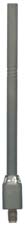
SOURCES; Low band & PRC-127 Rubber
Duckies
Of the several companies that make rubber duckie type antennas for
low band VHF radios (30-50 MHz) Centurion is the only company that
makes a viable product. Though they produce several variants
(including Deluxe & Heavy Duty) there is only one model that is
worth consideration (and it's not the expensive one).
What makes this antenna unique among low band duckies is that
it's field tunable. A field strength meter and a standard plastic
tuning wand (supplied) are all that's needed to make this antenna
operable on any radio, or frequency you wish. This is accomplished
by simply removing the plastic cap at the top of the antenna,
inserting the tuning wand, and adjusting a slug. It works great.
At about 10" long, the antenna outwardly seems identical to those
made for the CB market about 10 years ago (supplied with many HT,
& emergency type CB's). I have been using these antennas for
years, and have found absolutely nothing that even approaches
their quality & performance.
As the catalog I have seems to have the pictures &
descriptions inverted I'll not give you the model number of the
antenna. And as it's available with every conceivable connector
style it wouldn't do much good anyway. I believe that what
your after is the Style
'L' < note this link is NOT to the field tunable
version, working on it, Brooke> field tunable 30-50 MHz.
Neoprene shrink sleeve. Do not get the injection molded version as
it is base loaded/tuned, not as efficient, looks like a miniature
Saturn Rocket, is more expensive, and is only slightly more
flexible than a broom handle.
If you are a user of a PRC-68 family
radio, you know that it is capable of using a 6" duckie (not
worth a shit!), long rubber helical (pretty good), and tape
antenna similar to, or even the same as that of the PRC-25/77. You
may not know that it can also be used with a standard 50 ohm load.
The problem is, that to swap between any of these options the
radio must be taken apart & retuned. With the Centurion Rubber
Duckie you can align the 68 for use with a 50 ohm load, and swap
between it & the Duckie (once properly adjusted) at will
without the need of retuning the radio. The performance of the
Duckie will be far better than the original 6 incher, and on a par
with, if not better than the 1.5 foot rubber helical.
Centurion is also the company that makes the distinctive antenna
used on the PRC-127 & I've been using them for years (even
before the PRC-127 existed). This is listed as their Style "H" broad band.
If you need a new antenna for your PRC-127 (or any other high band
VHF or 2 meter radio) here you go. You can buy them direct
from the OEM for less than they go for on Ebay! They will
make a 2 watt VHF radio think it's a 5 watter (if it's using a
standard 6" duckie)!
If you have a low band HT that was intended to use a high band
telescoping antenna, wish to use a rubber duckie, and do not want
to mess with removing radio's internal load coil, this is the one
for you (I use it on my RCA/Comco/Repco clones)!
Centurion International
http://www.centurion.com/
P.O. Box 82846
Lincoln Nebraska 68501
USA
USA & Canada
Voice 1-800-228-4563
Fax 1-800-848-3825
International
Voice 402-467-4491
Fax 401-467-4528
You might check to see if they yet have a web site, or e-mail
capabilities. If they do, let me know.
If there is a lot of interest we may investigate a quantity
purchase as a group. Again, let me know.
Dennis Starks; Collector/Historian
Midwest Military Communications Museum
Box 95, Cross Timbers Mo. 65634 USA
email: military-radio-guy@juno.com
Back to Brooke's PRC68, Products for Sale, Military Audio, Squad
Radio, Military Information,
Personal Home page
Page created 10 June 2001.