Background
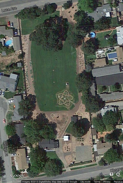
Within a year or two of moving to Ukiah (early 1990s) I saw a
street sign "Observatory Ave." and turned onto it searching for
an observatory and found a roll off roof observatory. The
local historical building had a little information about
it. This web page is about the Ukiah latitude observatory
(Wiki)
part of a half dozen identical observatories all located at the
same latitude all around the world.
Official Ukiah Latitude Observatory facebook
web page.
History
See Wandering Pole, Wobbling Grid (Reference5
) for some history.
Euler's (
Wiki)
paper
Theory of the Motions of Rigid Bodies in 1765
predicted the wobble of the Earth (
Wiki)
which is in addition to the precession (
Wiki)
that takes about 26,000 years for one cycle.
From the
Wiki
page on Stellar Parallax:
"
James Bradley first tried to measure stellar
parallaxes in 1729. The stellar movement proved too insignificant
for his telescope, but he instead discovered the
aberration of light,
[5]
the
nutation of the Earth’s axis, and
catalogued 3222 stars." In 1729 the precision of angle
measurements (see:
dividing
engines below) was not adequate to the task.
Nutation is related to the angle of the Earth's spin axis relative
to the plane of the Earth's orbit around the Sun. It is not
related to the latitude of an observatory.
From the Wiki page on James Bradley:
"Bradley's discovery of the
aberration of light was made
while attempting to detect stellar
parallax.
[5]
Bradley worked with
Samuel Molyneux until Molyneux's
death in 1728 trying to measure the parallax of
Gamma Draconis."
German astronomer Karl Friedrich Küstner (
Wiki)
discovered Polar Motion of the Earth (
Wiki) in
1888.
1890 - Progress of Astronomy by William C. Winlock (see short
article below in Dividing Engines
section) data showed the latitude problem
Wandering
Pole, Wobbling Grid by Trudy E. Bell, 2016 - Interesting
scientific history that lead up to the Latitude observatories.
|
Side Bar - Brooke's speculation:
Aberration of Light
This may have been related to measurements made to
better understand Aberration of light (Wiki,
Wiki2).
This was a scientific problem that lasted from
about 1758 until Einstein's (Wiki)
theory of special relativity (Wiki)
in 1905 that talks about moving and fixed
reference frames.
For example the position of a star (for example
the North star) observed from the Earth in, it's
orbit around the Sun, will vary because of
aberration (Wiki: annual
aberration). The constant of
aberration is about 20.5 arc seconds and the
amount of change in a stars position depends on
the declination of the star and the latitude of
the observatory. So the wobble of the Earth
would introduce an error in measurements of these
small angles.
A common example is the idea of standing still in
the rain where it falls straight down (no wind)
compared with standing up in a convertible moving
forward. When standing still the rain
appears to come from straight overhead and when
moving it appears to come down at an angle.
In a similar way the light from a star appears to
come from different places depending of the the
movement of the Earth.
|
This means that the location observatories in relation to
the spin axis of the Earth are also changing. The
next year a handful of observatories measured their
latitude for a year and found a variation. As would
be expected observatories close in longitude would have
the same latitude variation (top 3 plots) and an
observatory on the opposite side of the Earth would be out
of phase (bottom plot).
Ref: On the contribution of the Geodetic Institute Potsdam
to the International Latitude Service, Joachim Höpfner,
Paper presented on the occasion of the centennial of the
first observations of the International Latitude Service
in 1999
Note that one division on the vertical axis is 0.1 arc
seconds and the total variation over a year is about 0.5
arc seconds.
Even today it's far from a trivial exercise to measure
angles this small. The GPS in a cell phone can not
do this yet (2015).
|
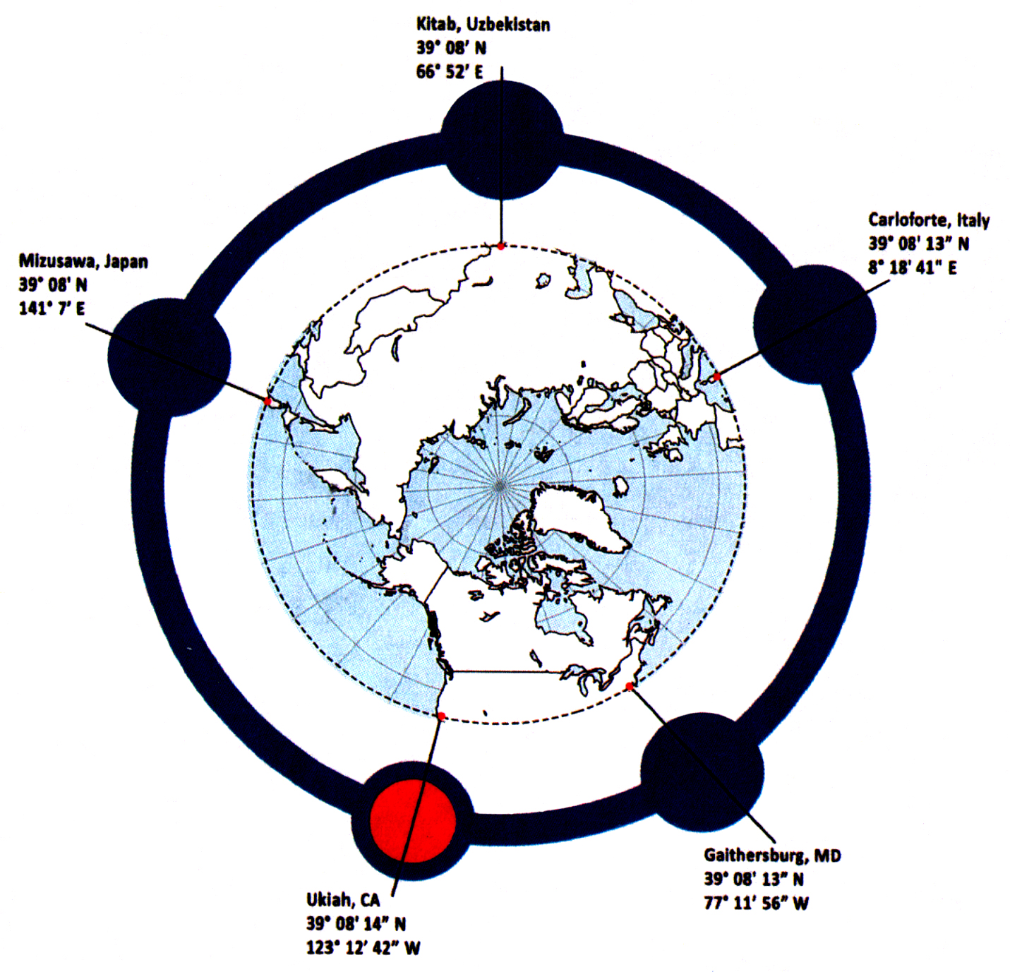
Starting
in 1899 observations were made to determine the location of the
Earth's rotational axis, i.e. finding the latitude. To do
this a handful of observatories were spread pretty much equally
around the globe at 39 degrees 08 minutes North Latitude.
They sequentially observed the same set of about 60 star pairs
each night measuring the zenith distance and time of meridian
crossing using a Vertical Zenith Telescope (VZT).
[Brooke's note:] It may have been called finding the latitude
because of the effort from 1730 to 1770 to find the longitude.
The book
Latitude by Carter & Carter ( ISBN
1557500169)
has a good description of the problem of finding the Latitude and
the brilliant work of Chandler and Newcomb. Ukiah was the
location of one of the small number of Latitude Observatories (
Wiki)
which measured their latitude (and longitude) nightly in order to
help define the wobble of the Earth's poles. The
observatories were started in 1899 and decommissioned in 1982.
Finding the Longitude was a separate but related problem since
Longitude (
Wiki)
and Latitude (
Wiki)
are the coordinates used to locate a place on the Earth.
The book Longitude
by Dava
Sobel describes the 40 year effort (1730 - 1770) that John
Harrison (wiki)
went through to develop the marine chronometer (Wiki).
There's also a movie based on the book called Longitude.
What
Harrison accomplished is fantastic both in terms of a marine
chronometer but also in terms of horology (Wiki).
For example he was the inventor of the temperature compensated
pendulum (Wiki).
But once accurate balance wheel clocks or better quartz clocks
or GPS navigation receivers are available the problem of finding
the longitude goes away.
Alfred L. Loomis (wiki)
got half a dozen of the Shortt precision pendulum clocks (Wiki) and
discovered that they were effected by the Moon's gravity and was
the first to publish this limitation of pendulum clocks (Wiki)
in 1931. The book Tuxedo
Park by Jennet Conant has details of that. Some
details of the Moon and Sun gravity tides is on TVB's web page Lunar/Solar
Tides and Pendulum Clocks. Also see Earth Tides and Lunar Ranging.
The movement of the North pole caused by the wobble of the Earth
was a much larger problem that took longer to solve than the
longitude problem. Many astronomical observations can not be
made without a knowledge where the North pole is located (i.e.
where the spin axis of the Earth is pointing in space). The
Latitude Observatories operated for almost a century. It's
only been very recently that a connection with El Nino and the
wobble has been found. The problem with the wobble is that
it's not predictable as of 2007.
The
Wiki
page for Chandler Wobble Measurement mentions earthquakes
but I think Plate Tectonics (
Wiki)
is a more likely explanation that includes earthquakes and
movements of gigantic mass thus effecting the angular momentum of
the Earth. This may be a way to account for the timing of
the ice ages (
Wiki)
There are a number of modern ways that the orientation of the
Earth is currently being measured. This is coordinated by
the
International Earth
Rotation & Reference Systems Service in
France. They make use of such methods as laser range finding
to Earth satellites (
Wiki)
and the Moon (
Wiki)
(
Lunar Ranging below) and Very Long
Base Line Interferometry (
Wiki).
In the 1977 NOAA report (See References below) they say "Probably
no other project in modern science has continued for so long
unchanged in purpose, equipment, or technique and has managed to
produce such a large volume of high-quality data."
When reading old papers about the Earth's wobble, like for
example: Leaflet No. 111 - May 1938, The Variation of Latitude by
William F. Meyer, UC Berkeley, you need to remember it was written
prior to plate tectonics (
Wiki)
which really became the current accepted science starting in the
early 1970s. From 1912 to the early 1950s there was the idea
of continental drift (
Wiki)
which was controversial during all that time, so papers written
between 1912 and the late 1950s may or may not mention continental
drift and so far I haven't seen any that mention plate
tectonics. In the book
Annals of the Former World by
John McPhee written in 1998 there are still disputes about where
plate tectonics may and may not be the real answer to
observations, so even now we don't have a firm grip on all the
details.
Prior to GPS (
Wiki)
the maps of each country used a datum in that country, that's to
say there was no model of the Earth. While the World
Geodetic System of 1984 (Wiki:
WGS84)
was not the first, it's the default system in today's GPS
receivers. I mention this because knowing the latitude and
longitude prior to 1984 involved a reference datum that was unique
to each country. So when the Lon and Lat of an observatory
are mentioned in the old literature remember it's a local
measurement.
The basis of each countries datum was probably a meridian circle (
Wiki)
for observing stars, but the location of those stars was not well
known. I expect the position of stars is an on going
refinement and in the late 1800s and early 1900s the star
positions were not well enough known to detect the wobble by
observing any star and using it's "catalog" (
Wiki)
location. In fact the reason that the latitude observatories
were located at 39 deg 8 min North was so that all observatories
would look at the same stars and so could both determine the
latitude and as part of that process develop an accurate
declination value for those stars.
A short YouTube video about the Maryland latitude observatory:
NEWSLINE: Gaithersburg Latitude Observatory
Telescope Site Visit
About a meeting of surveyors in Nov 2014.
Causes and Types of Polar Motion
There are forces acting on the Earth
that cause it to orbit the Sun and translate in space that are not
related to to the latitude problem. They result in the
precession (
Wiki)
and nutation (
Wiki)
of the poles.
The unbalanced forces that can effect the latitude come about
because the distance between the North and South poles is shorter
than the diameter at the Equator. This gives rise to a Euler
period of about 300 days if the Earth is assumed to be rigid or
the period Chandler predicted of about 305 days. Chandler
Wobble (
Wiki)
is added on top of the Euler spiral and is caused by the
circulation of air and water, earthquakes, continental drift (the
old name for Plate Tectonics) and changes in the Earth's interior
(2014) and
El Niño (
Wiki) ocean
currents.
If
El Niño has an effect then maybe global
warming will show up as a perturbation of the Earth in a way
that can be seen using precision astronomy or time? For example when a large
volcano erupts it changes the distribution of mass on the Earth,
in a way that's similar to an ice skater extending her arms,
that causes a change
in the period of the earth's rotation. See my Stellar Time web page for ideas
on how to measure the period of the Earth's rotation.
Conclusion: it may not be possible for someone measure the
Earth's rotational period in a backyard. That's to say it
takes some very expensive equipment to do it.
The Chandler Wobble (
Wiki)
amounts to about a 30 foot change which is about 1/3 of an arc
second.
Photographic Zenith Tube (PZT)
This is a zenith telescope where
part of the optical system is a pool of Mercury that reflects the
light from a star, through a lens system who's node is filled with
a glass photographic plate that's moved on a track at the sidereal
rate. After making 4 exposures the plate is read in a X-Y
measuring machine and from that the sidereal time of the exposure
can be determined to better than one millisecond.
It was replaced by atomic time in 1972 since an atomic clock keeps
much more uniform time that does the rotation of the Earth.
See my
Rb and
Cs
atomic clocks.
On some of my other web pages there's information about the PZT
but in reference to it's use to determine the time based on the
Earth's rotation. But in the D.O.C. U.S. Coast and Geodetic
Survey Special Publication No. 27, 1915 "Latitude Observations
with Photographic Zenith Tube at Gaithersburg, MD." is a
report on the use of the PZT. (
atitudeo00uscouoft.pdf)
In this paper problems with earlier observation methods are
described.
The Royal Observatory -
PZT
has a photo of the PZT.
The PZT was found to be no more accurate than the zenith telescope
and much larger, more complex and expensive so the Latitude
Observatories did not switch to using it.
2384666
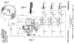
Astronomical camera,
Donald
L Wood,
Eastman
Kodak Co, 1945-09-11,
356/148; 356/249;
396/322; 396/332; 396/429 - appears to be a mini PZT.
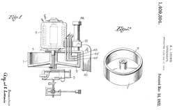
2968228
Zenith and level recording camera and level, Everett
L Merritt, PHOTOGRAMMETRY
Inc, 1961-01-17
Patent Citations (12)
Publication
number Priority date Publication date
Assignee Title
US1378011A *1921-05-17
Telegraphic Register Receiving Apparatus
US1533941A *1924-10-25
1925-04-14 Nl Tech Handel Mij Giro
Gyroscopic apparatus having a means for indicating the
inclined position of an airship or the like
US1653585A *1926-03-05
1927-12-20 Maurice R Pierce Camera sextant
US1880960A *1929-06-03
1932-10-0 4Jr Charles F Keale Aerial camera
US2047070A *1927-02-22
1936-07-07 Horner Erich Device for
photographic survey from aircraft
US2231378A *1941-02-11
Motion picture printing machine
US2352644A *1942-07-15
1944-07-04 Jr Garrett B Linderman Apparatus
for estimating ranges
US2375356A *1942-09-011
945-05-08 Bausch & Lomb Optical
instrument
US2402216A *1946-06-18
Means for securing improvements in
FR948680A *1947-07-01
1949-08-08 Indicator and recorder gyroscopic
vertical
US2671388A *1948-07-27
1954-03-09 Leo N Brubaker Method and
apparatus for determining tip and tilt in aerial survey
photography
FR1079027A *1952-07-28
1954-11-25 Kollsman Instr Corp artificial
horizon
Cited By (11)
Publication
number Priority date Publication date
Assignee Title
US3037284A *1960-10-17
1962-06-05 Gen Precision Inc Self-contained
celestial navigation device
US3052169A *1959-12-14
1962-09-04 Voigtlaender Ag Viewfinder for
single lens reflex cameras
US3166623A *1960-12-29
1965-01-19 Link Division Of General Prec
Spherical lens imaging device
US3197782A *1961-12-27
1965-07-27 Cordis Corp Optical recording
system
US3236167A *1963-12-16
1966-02-22 Rosemount Eng Co Ltd Underwater
camera
US3628027A *1969-12-17
1971-12-14 Sulzer Ag Beam deflecting and
focusing means for photoelectric monitoring, counting or
control apparatus
US4889409A *1988-02-16
1989-12-26 Ball Corporation Hemispherical
retroreflector
US5367407A *1990-12-13
1994-11-22 Karl Friedrich Angstenberger
Apparatus for supporting an aiming and orienting
appliance useful in reflector systems
US5392112A *1992-03-11
1995-02-21 Nikon Corporation Inclination
angle metering apparatus
US20070293847A1 *2002-03-29
2007-12-20 Codman & Shurtleff, Inc.
Optical Height Zeroing Device
US20130100536A1 *2009-02-06
2013-04-25 Ems Technologies, Inc. Shaped
gradient lens
2995992
Zenith camera system, Everett
L Merritt, PHOTOGRAMMETRY
Inc, 1961-08-15, 396/50; 356/148; 356/249; 359/557; 359/665;
396/12 -
3001290
Gyroscopic compass, Rellensmann
Otto, Stier
Karl-Heinrich, Lear Inc,
1961-09-26, 356/148; 33/275G; 33/285; 33/315 - North Finding
The
new CCD Zenith Tube IAU No. 248, 2007 - to replace the
1969 PZT made by Carl Zeiss, Jena
History of Photographic Zenith Tube (PZT) -
looking
for information by
Julien Gressot
-
Video, 24:24 -
requires giving them access to your contact list.
Related
Navigation
Stellar Time
Keeping
Surveying
MD1 Astrocompass
Pendulum
Astrolabe
Theodolite
Time &
Frequency
Plate Tectonic Motion (Wiki)
One of the first indications that "Continental Drift" (Wiki)
existed was from archeology (Wiki) in
relation to Fossil Distribution (Hyper
Physics). This evolved into tectonic plate motion.
"
The
secular variation of longitudes and plate tectonic motion"
describes how the data from the Latitude Observatories were used
to test the plate theory. This implies that the time of star
meridian crossing was measured along with the zenith angle.
Zenith angles would give latitude variations but to also see
longitude variations time observations would be needed.
Brooke's theory - Plate tectonics may be the cause of the
wobble. That's because very large masses are moving around
on the surface of the Earth thus changing it's center of mass
hence the spin axis.
Note that tide gauges (
Wiki), used
to measure sea level are anchored to tectonic plates and so really
do NOT measure sea level, but rather the difference between the
elevation of the gauge and the level of the water. Some tide
gauges, like the one in Eureka, are moving upward as the Pacific
Plate (
Wiki)
pushes on the Juan de Fuca plate (
Wiki)
(in the Pacific North West) causing the Western edge of the Juan
de Fuca plate rise. Therefore tide gauge data needs to be
corrected for the vertical motion of the plate. Modern tide
gauges are coupled with GPS receivers and
gravity meters to back out the
movement of the ground under the gauge.
Ukiah Astronomers
I've tried to compile some information on who the astronomers
have been here in Ukiah.
No.
|
Ukiah
Years
|
Astronomer
|
References
|
1
|
1899 to
1903 |
Frank Schlesinger (Wiki)
|
Cal
Micrometer
|
2
|
1903 to
907 |
Sidney D. Townley (Wiki)
April
10, 1867 - March 18, 1946
|
San Francisco Earthquake
damage in Ukiah: 5:12 AM - April 18, 1906
Assistant Professor of Applied Mathematics at Stanford
in 1907 - 1946
charter member & Editor of
Seismological
Society of America 1911 to
1929
|
3
|
1907 to
1912
|
James D. Maddrill
|
American
Astronomy: Community, Careers, and Power,
1859-1940 By John Lankford, Ricky L.
Slavings, 1997
"James D. Maddrill (1880 - ?) illustrates a unique form of
failure. I know of no other case in which the
doctorate (1907) was conferred before the
dissertation had been completed. Just how Maddrill
convinced William Wallace Campbell and the graduate dean
at Berkeley to enter into such an arrangement is
unclear. In any case, Maddrill assumed the post of
director of the Ukiah International Latitude Observatory
with a Ph.D. but still had to complete the dissertation in
astronomical spectroscopy. Campbell continually put
pressure on Maddrill, who responded with excuses that
included physical and mental illness as well as the
distraction of a failed love affair. Maddrill
apparently made little progress and in 1912 left Ukiah for
Berkeley where he hoped to complete his theses. It
is not clear whether this was ever done. At all
events, Maddrill's astromonical career came to an end and
he disappeared from view."
|
| 4 |
1912 to 1922
|
U. F. Meyer
|
|
5
|
1922 to 1946
|
H.
G. Wrocklage
|
|
6
|
1946 -
1972
|
Leonard F. Caouette
|
1988
star pairs observed (1611 in Gaithersburg)
|
7
|
1972 -1982
|
Robert Pettey
|
|
Latitude Observatories
The observatories built specifically
for the International Latitude Service were all located very near
39 degrees 8 minutes North Latitude. The observation method
was as developed by Talcott in 1834 which requires observing pairs
of stars where the distance is balanced on the North and South
(East & West?) sides of the zenith and the time of culmination
is reasonably close. This allows making better measurements
than prior methods. It requires that the observatories be
located all around the Earth and very close to the same latitude
so that they are looking at the same star pairs thus allowing for
error corrections. Note when this program was started the
proper motions (
Wiki) of
the stars was not known so the actual star locations needed to be
determined along with measurements of each observatories latitude
and longitude.
At the time that a decision was being made about where to locate
the observatories Japan was very concerned with geology because of
the Nobi earthquake of 1891and wanted to be part of this system
thus fixing the latitude of 39:08 North for the rest of the
observatories (
Ref 5). Note that
earthquakes are also related to the Ukiah observatory by the work
on seismometers by Townley (
See above).
Equipment
Needed Accuracy
The wobble is on the order of 30 feet. A rule of thumb is
that one arc second of angle change along a line of constant
longitude (i.e. changes in latitude) is about 100 feet, then the
total magnitude of the wobble is about 0.3 arc seconds. It
would be good to measure at least to 10% of the thing being
measured or better 1% so the accuracy of the final measurement
should be on the order of 0.03 or better 0.003 arc
seconds. If many measurements are made and then averaged
the improvement goes as the square root of the number of
readings. Until I learn more about how the measurements
were post processed it's hard to say how good an individual
measurement needs to be.
To check plate tectonics in say 1965 there would be 66 years of
data. If observatories were moving 2 inches per year then
in 66 years there would be a change of about 132 inches or 11
feet. Since 11 feet is in the same order of magnitude as
30 feet plate motion should be detected and it's direction
determined. This would require that the observed transit
times be converted into Lat and Lon.
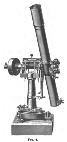
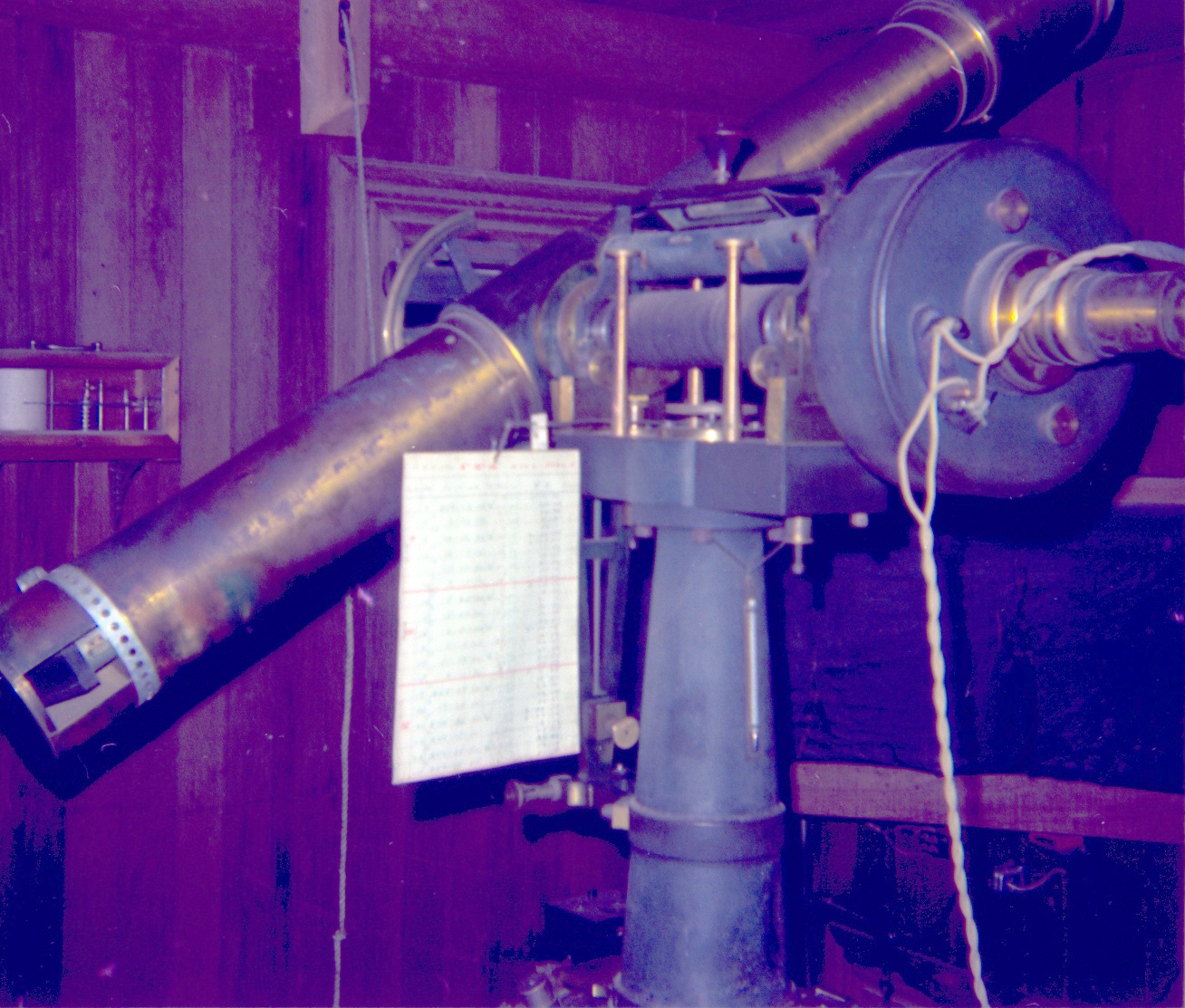
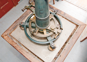
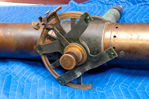
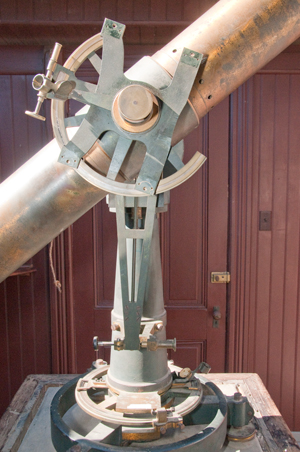
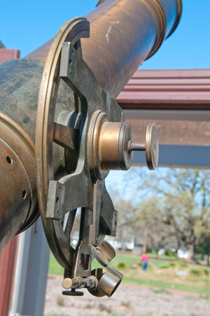
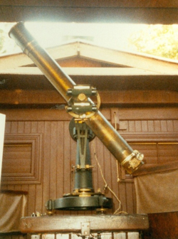
Zenith Telescope (Wiki)
The telescope is made specifically
for measuring the angle between straight up and a star near the
zenith. Or more accurately said to measure the difference in
declination of a star pair where both stars have about the same
declination but are on opposite sides of the zenith. This is
done using an eyepiece micrometer. That means the scale
factor depends on the actual focal length of the telescope.
To measure that I'm guessing double stars were measured or better
a test target on the ground was measured.
American History -
Zenith
Telescopes -
Julius
Wanschaff made the Ukiah scope. 108 mm ( 4 1/4")
aperture and 1300 mm (51.8") focal length (f12).
This is a much higher quality instrument than the earlier
Troughton & Simms zenith scopes. I've heard that the
angular accuracy was good to 0.1 arc seconds (or better).
This is orders of magnitude higher than today's high end
telescopes. The key difference is that this high precision
is limited to the specific type of measurement. If the
zenith telescope telescope was asked to point to a random star it
would do a much poorer job than a modern scope that has maybe a
few arc seconds accuracy.
A Meridian circle (
Wiki) is
a telescope with a single horizontal axis. They are used to
measure the time when a star crosses the local meridian
(North-South line).
The maximum useful magnification (power) of a telescope is on the
order of 50x to 100x for each inch of objective diameter, so for
this 4-1/4" objective the power is in the range of 212x to
425x. That means the focal length of the eyepiece needs to
be in the range of 1/4" (6mm) to 1/8" (3mm).
Note that Wild patented a
theodolite
in 1907 and by 1926 was making 1 arc second theodolites (
T2) and later made the T4
good to 0.1 arc seconds. But the Ukiah observatory may have
been making measurements good to 0,01 arc seconds in
1899! A feat that even today is fantastic.
The astronomer would press a button when the star crossed the
horizontal line to mark the chronograph. But the key
operation would be to adjust the pointing of the scope to measure
the zenith angle of the star as it rises to maximum height and
then recedes.
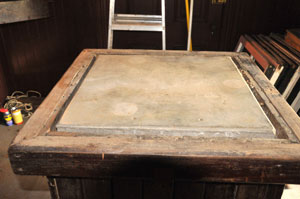
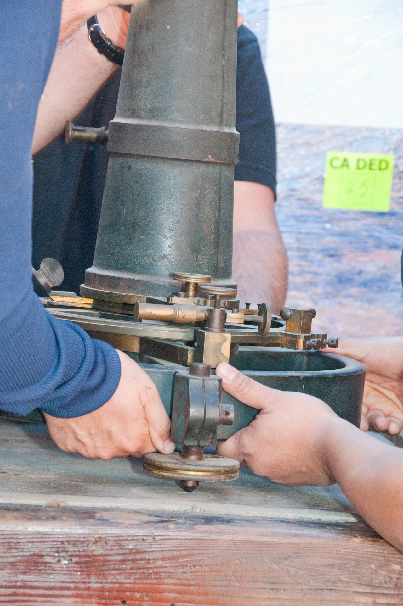
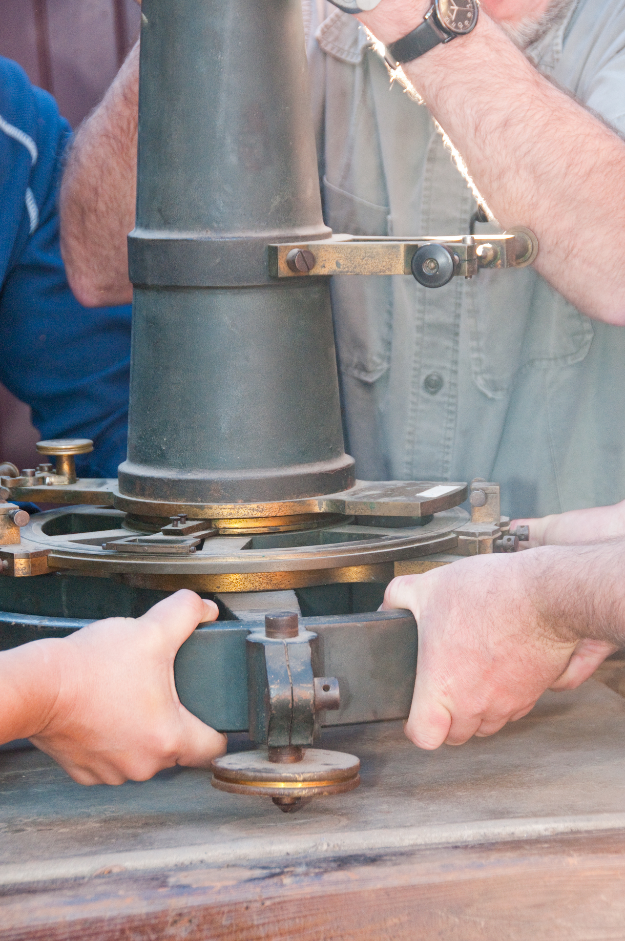
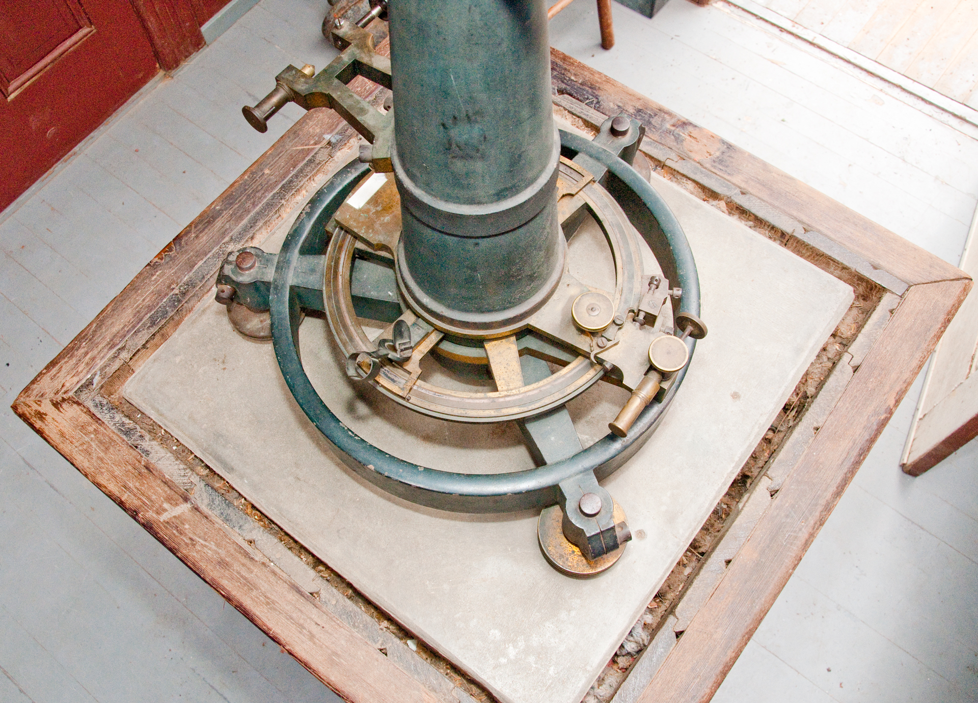
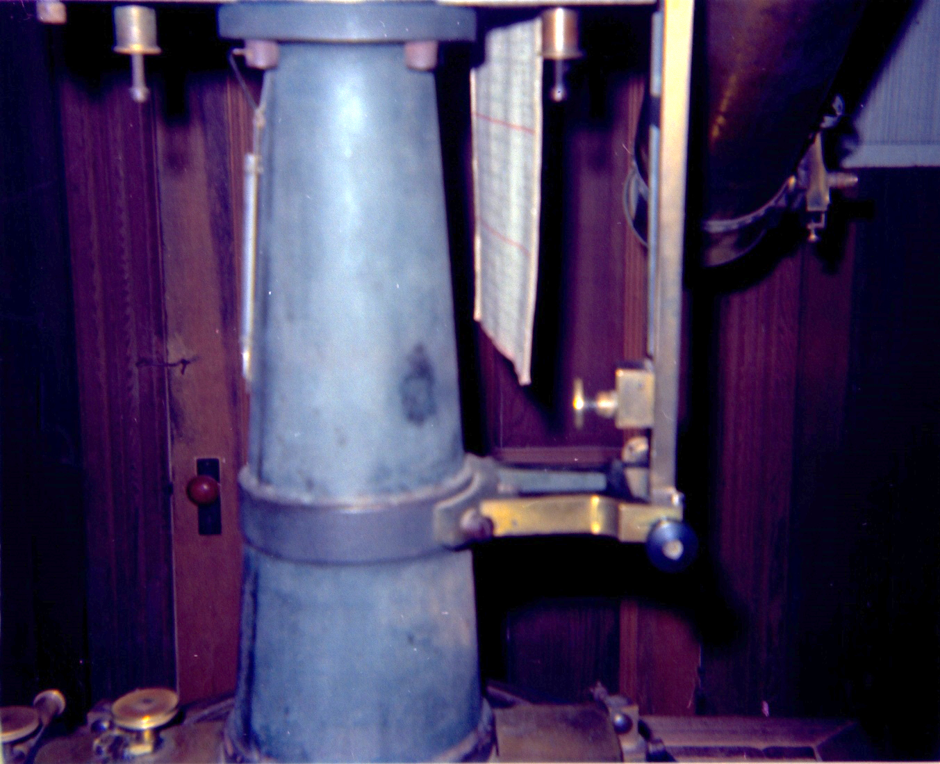
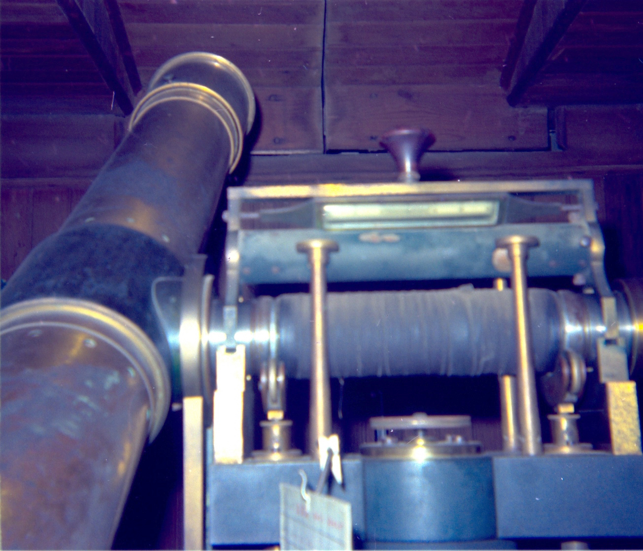
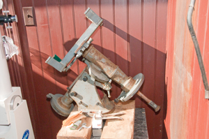
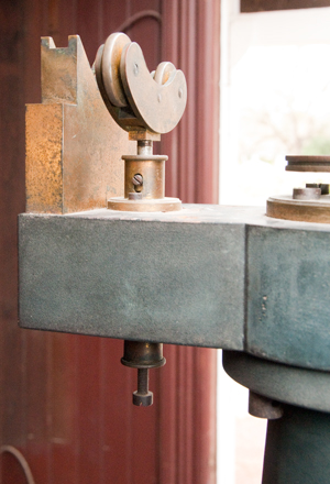
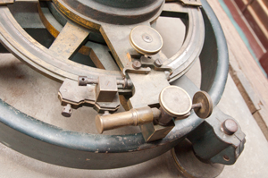
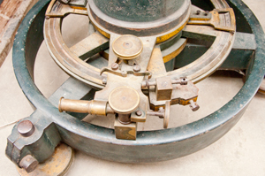
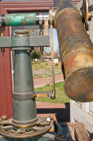
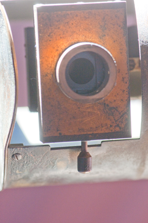
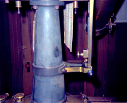
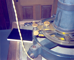
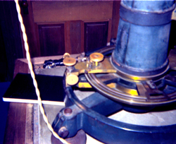
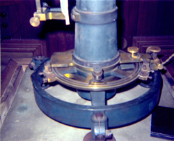
This is the concrete
pier for the vertical zenith Telescope. It's a waist high
concrete pier surrounded with wood that matches the interior
walls. You can see three light colored circles where the
feet of the telescope sat. The observer sat in a chair and
looked into an eyepiece that was maybe half a foot above the
concrete. In front of the observer was an electrical switch
that when activated would make a mark on the chronometer paper.
You can see three circles and when looking closely in each circle
there are three indentations in the concrete that may be been
small (about 1/32") on the bottom of the three coasters that were
between the telescope mount and the concrete.
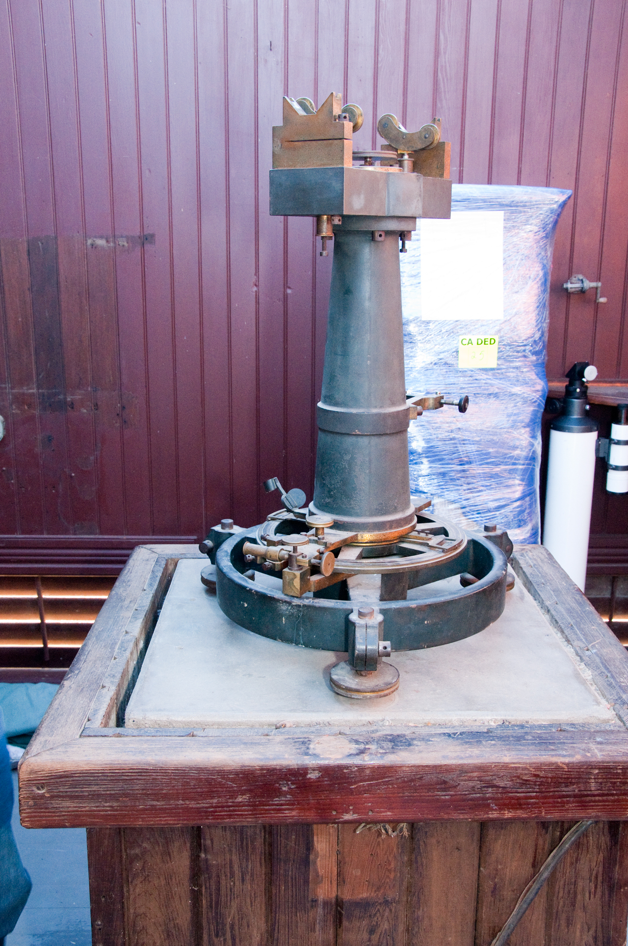
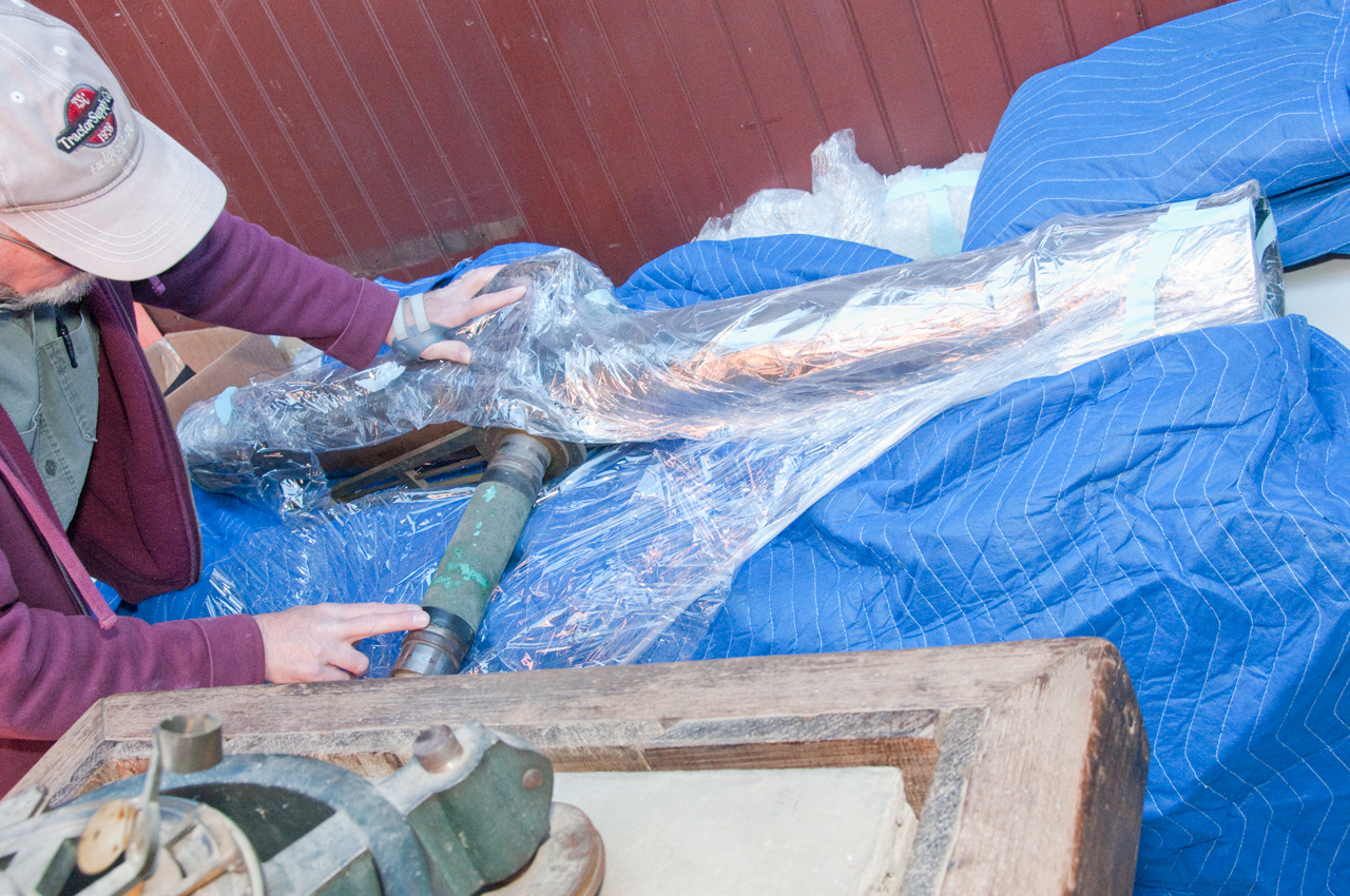
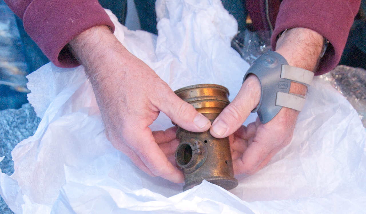
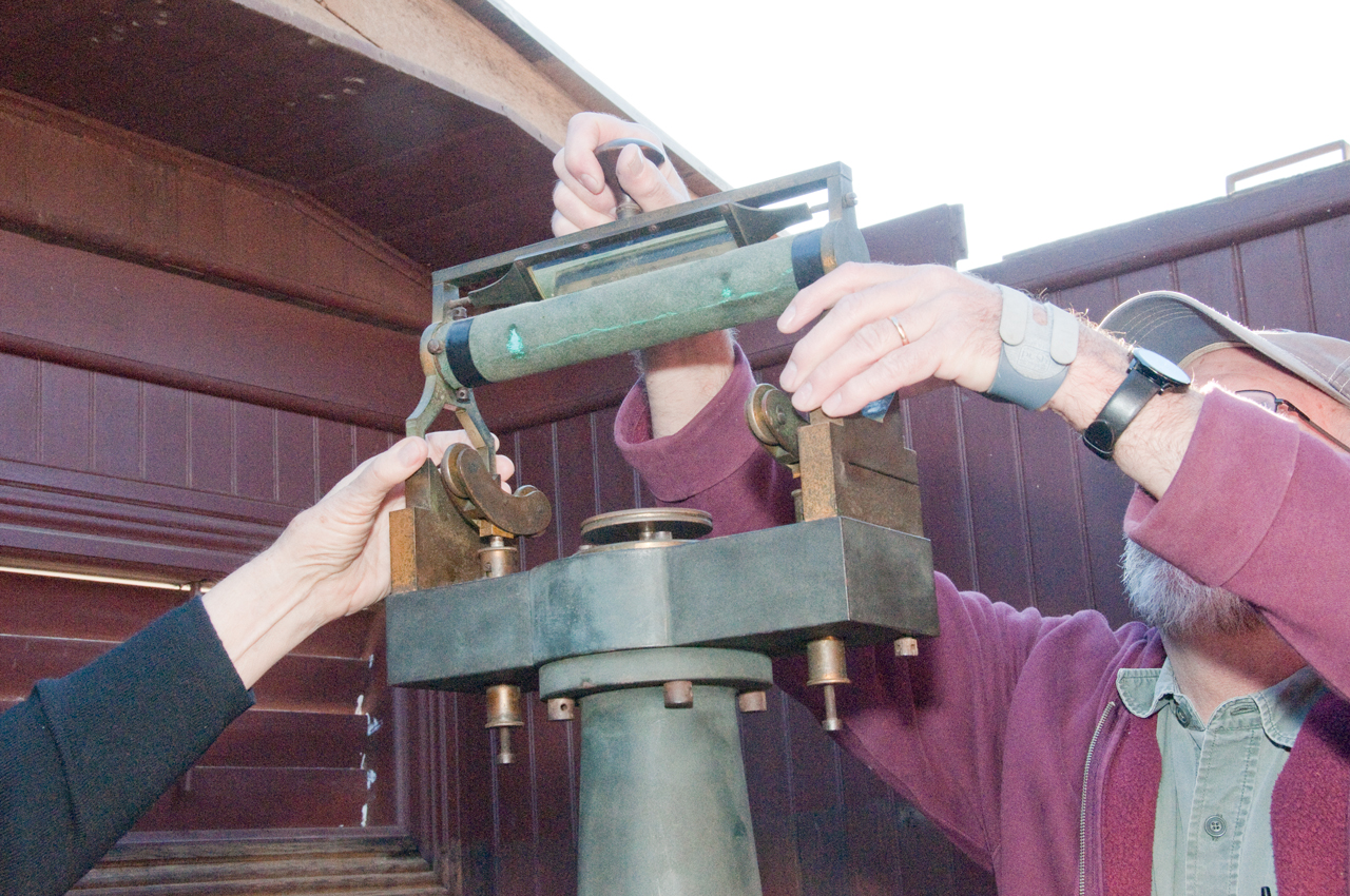
Zenith Telescope back in Ukiah 31 Jan 2015
Unpacking (UP Fig) figures in order taken. Photos by
Brooke Clarke.
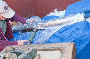
UP Fig 1 as installed by the movers the
mount is not positioned with the axis of the ways left
right in this photo
The microscope to read the vernier scale (Wiki)
is missing.
Blue shrink wrapped package in background is the sidereal
pendulum clock. Not unwrapped yet, will be in
interpretive building.

|
UP Fig 2 marked: J. Wanschaff, Berlin
|
UP Fig 3 The target building as seen from
the observatory
|
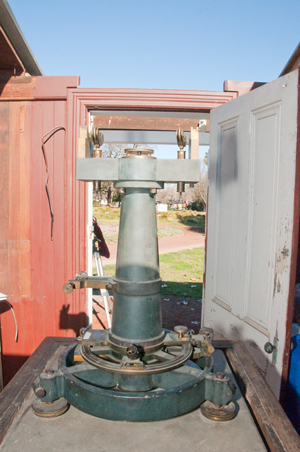
UP Fig 4 top of the mount with the "Y"
supports typical of a transit instrument (Wiki).
Note a surveyor's Wye level (description
on external page) has a provision to remove the
telescope tube from it's mount and reinstall it
reversed. This allows canceling some errors thus
making a more accurate measurement. I'm sure this
was done here too, probably at initial alignment and maybe
once every so many years for alignment checks.
|
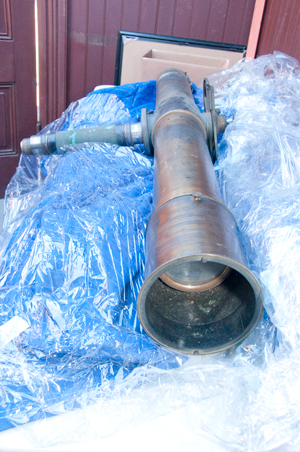
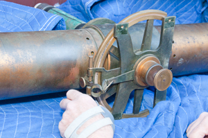
UP Fig 5 telescope tube
|
UP Fig 6 telescope tube
|
UP Fig 7 Light house. attaches to
counter weight

|
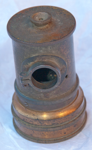
UP Fig 8 Light house. opening for
lamp. Thumb nut at top holds parabolic reflector.
I've heard that this electric lamp housing replaced a
similar one that used Calcium Carbide in Observatories
where there was no electricity. But Ukiah had
electricity from the beginning so didn't use that one.
|
UP Fig 9 Hole in shaft for light from
lamp house. Threads for counter weight.

|
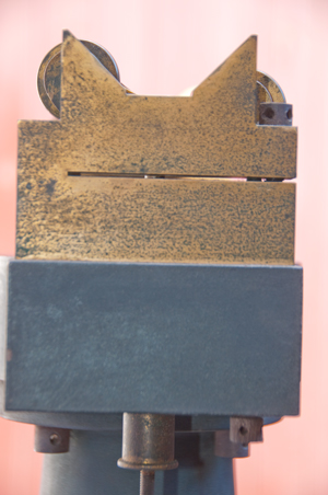
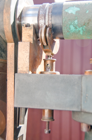
UP Fig 10 "Y" support on left has
slot allowing up/down adj.
"Y" support on right is solid metal.

|
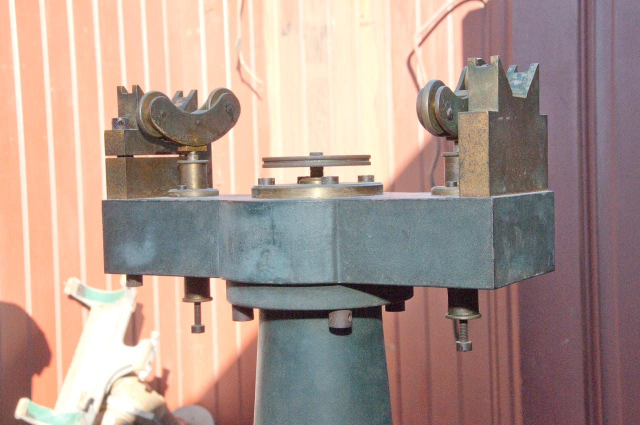
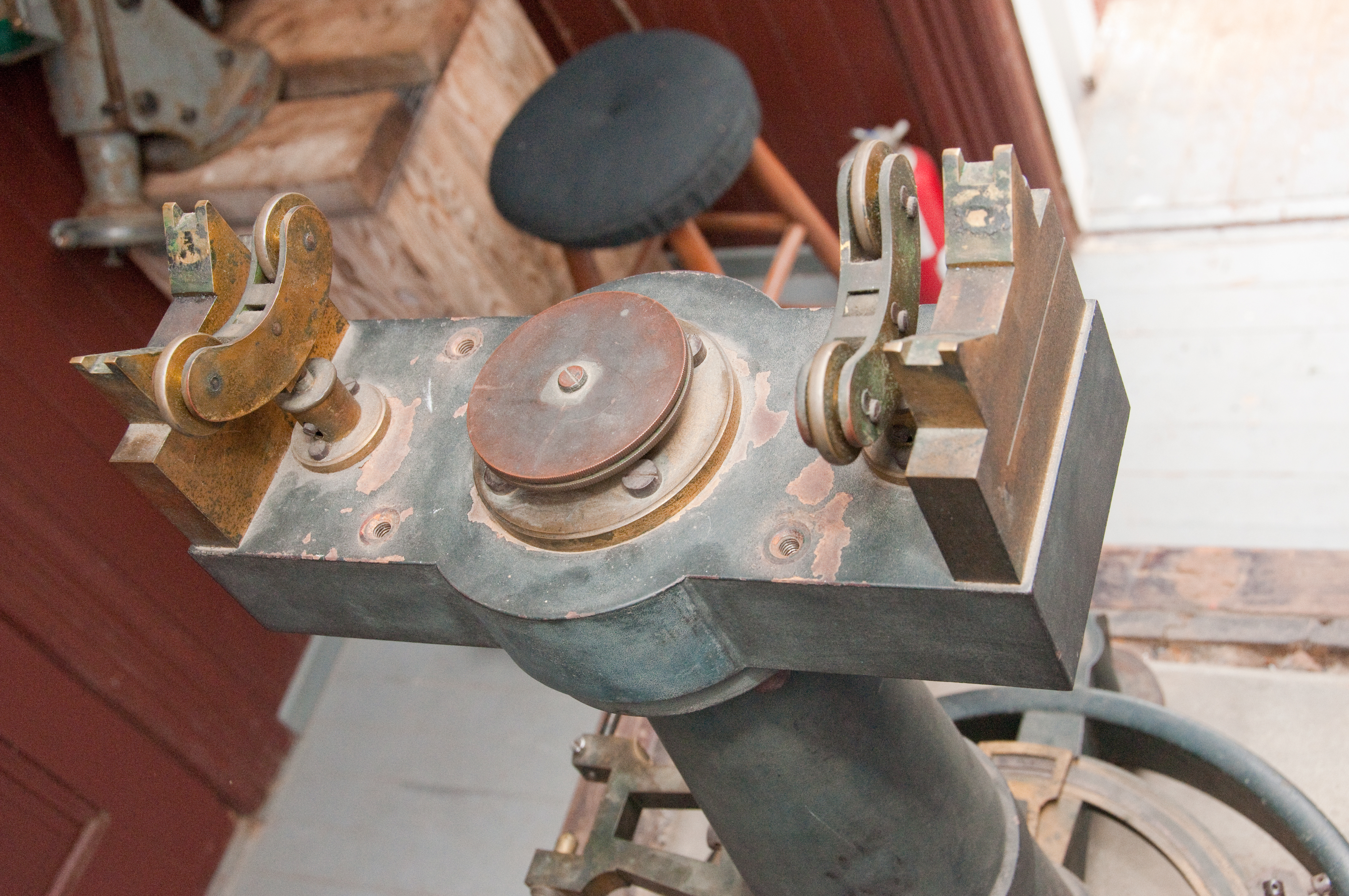
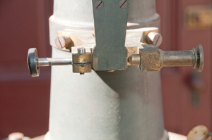
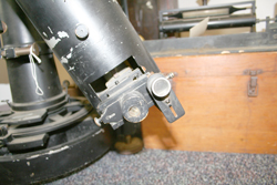
UP Fig 11 Arm on right has adjustment screw
for zenith angle adjustment. One vernier microscope
holder is installed, but the opposite holder is missing,
but it's 2 mounting screws are there.
|
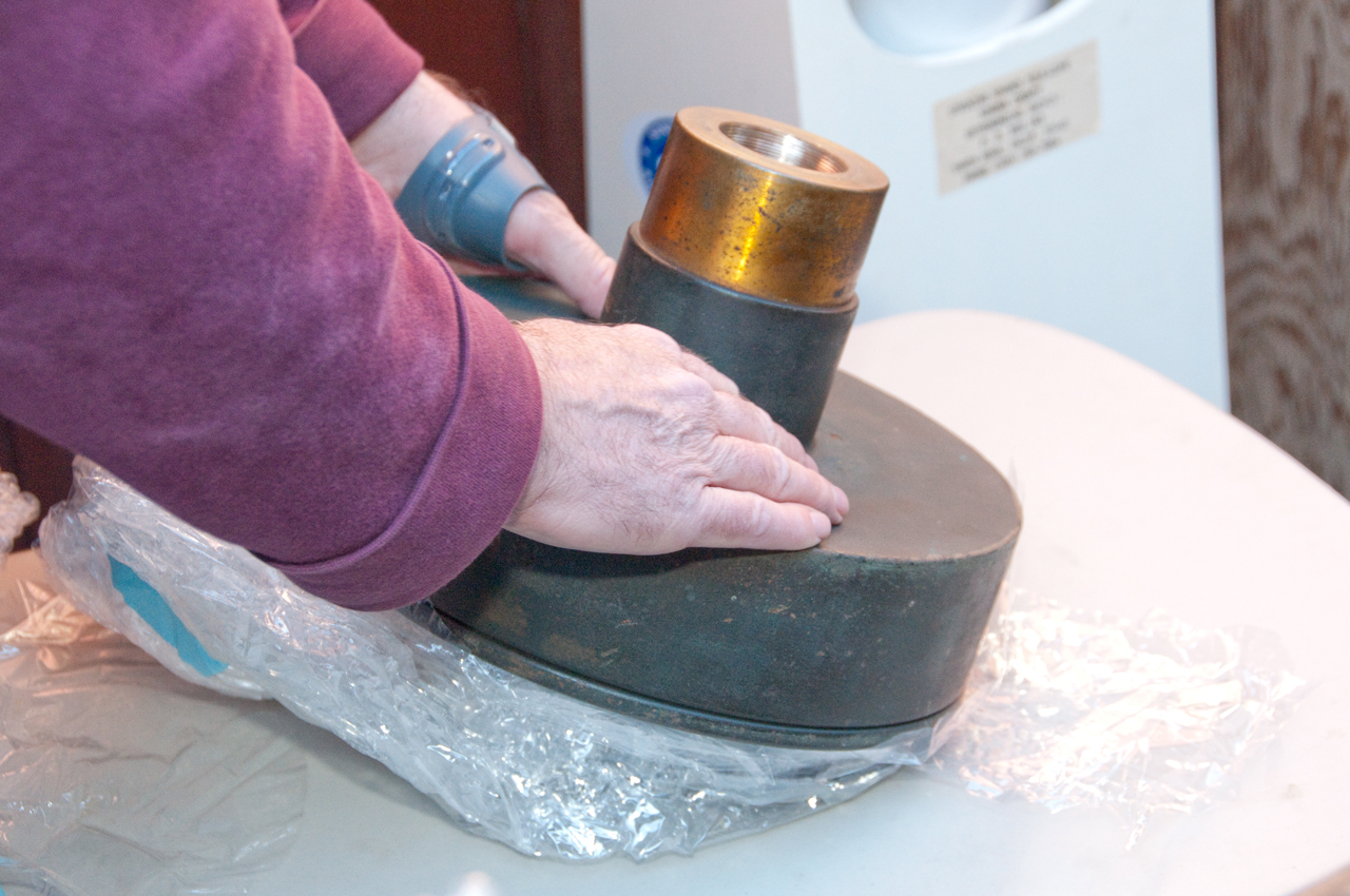
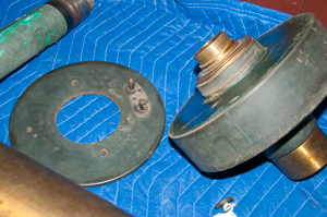
UP Fig 12 Counter weight
|
UP Fig 13 counter weight. Don't know
what the two thumb screws are for.
|
UP Fig 14 terminals on counter weight for
lamp house wiring
|
UP Fig 15 striding level. The 4 rods
that trap the striding level are missing.

|
UP Fig 16 striding
level.

|
UP Fig 17 striding level shown on telescope
bearing surfaces
|
UP Fig 18 target building
|
UP Fig 19 Behind door of target building,
hinged sheet metal panel at top closed.
|
UP Fig 20 Sheet metal panel opened showing
place holder wooden target bar.

|
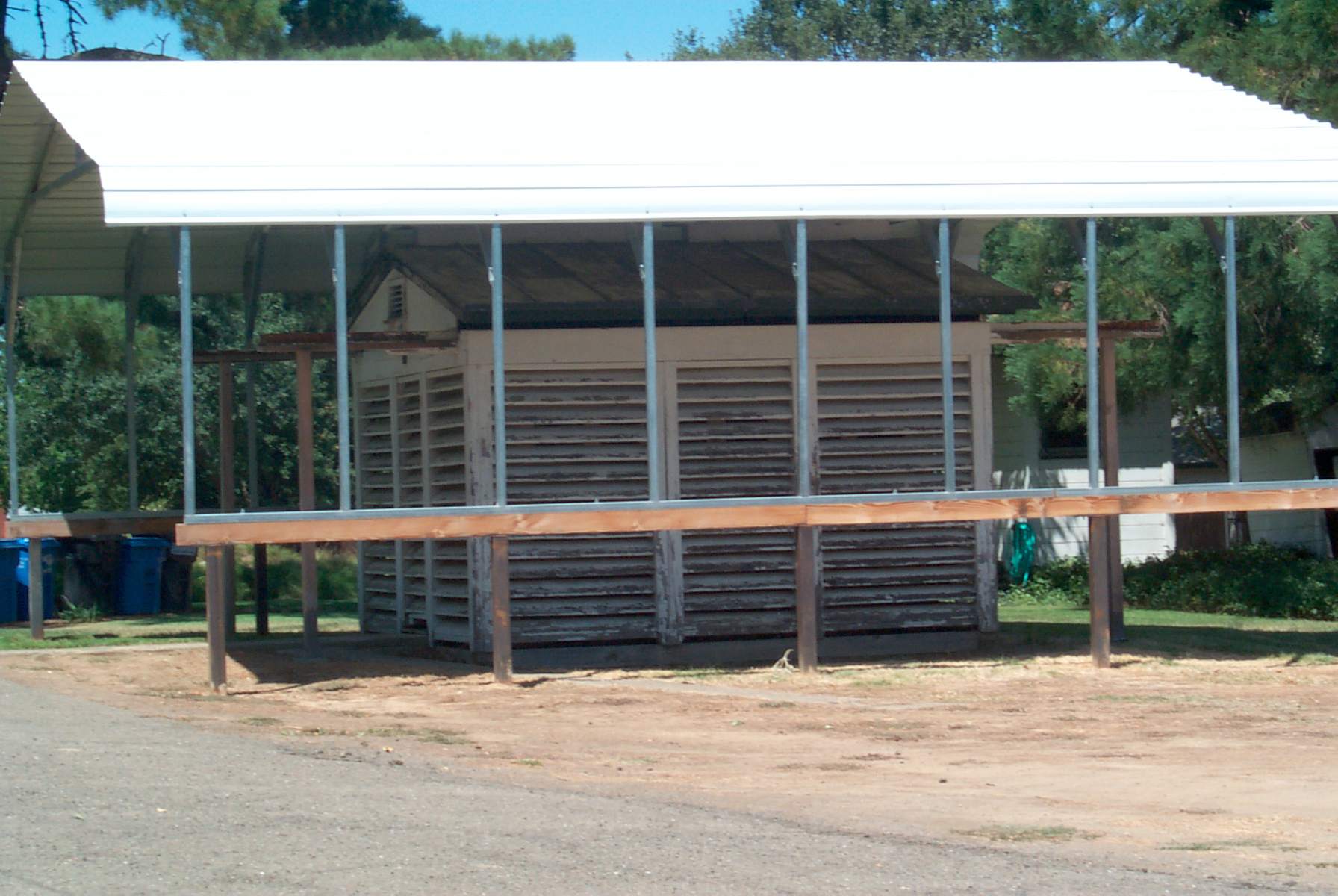
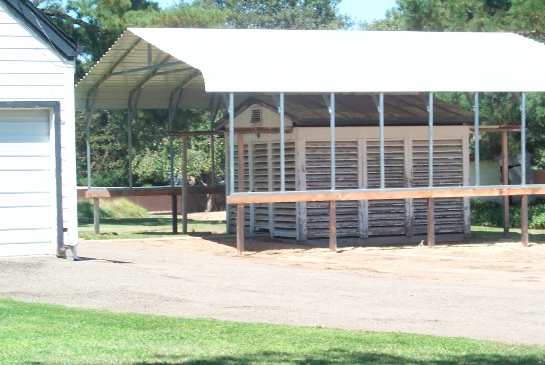
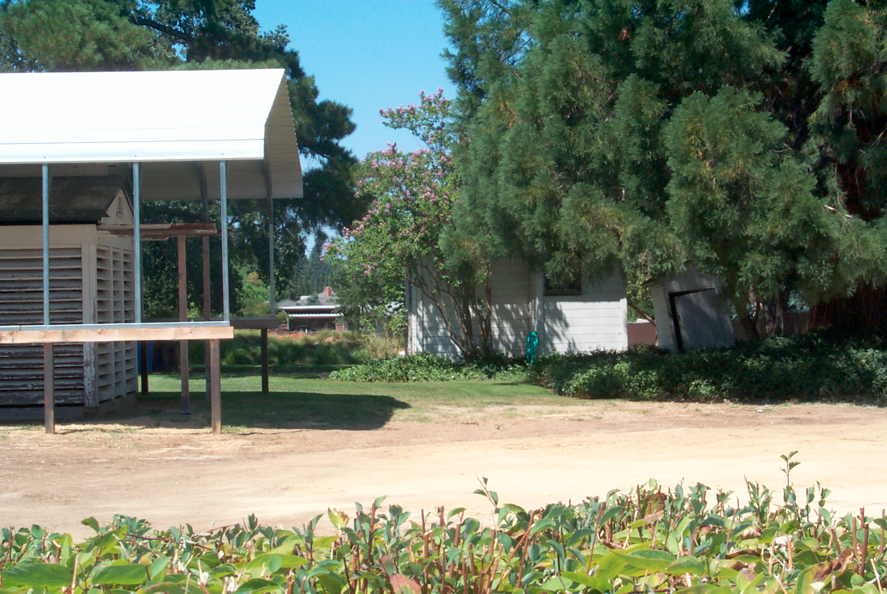
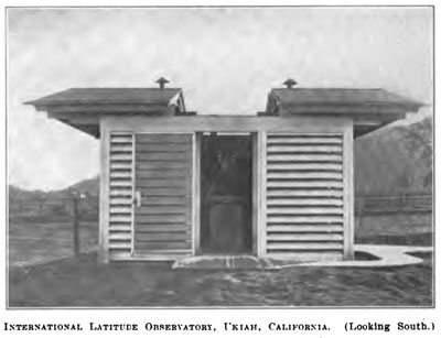
UP Fig 21 Roll-Off roof observatory
|
UP Fig 22 heating/cooling unit in
interpretive building
|
UP Fig 23 Target bar in interpretive
building after unpacking
Both targets can be independently adjusted to precisely
match the telescope offset.

|
UP Fig 24 right target
It's not clear why the left positioning bolt is
retracted.
Maybe after the target bar was removed someone was making
measurements or ???
|
UP Fig 25 left target
|
UP Fig 26 Target bar sitting in target
building.
Mystery vertical slit in the sheep metal. It was
copied from the original vertical slit see UP Fig 35 below
|
UP Fig 27 close up of target building.
Since there's no hole in the top of the sheet metal the
roof vent probably was to cool the building rather than
vent fumes from an open flame.
|
UP Fig 28 eyepiece end of telescope tube,
missing filar micrometer. (Wiki)

|
UP Fig 29 Vertical circle. vernier
microscope holder present, but the reading microscope is
missing.
|
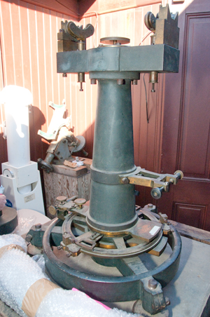
UP Fig 30 Rotating the mount to align
the "Y" axis.

|
UP Fig 31
Rotating the mount to align the "Y" axis.

|
UP Fig 32 Donated Equatorial mount (Wiki)
for another scope.
|
UP Fig 33 Target (Meridian) building seen
from properly rotated mount.

|
UP Fig 34 Target building seen from
properly rotated mount.
Note telescope can be aimed horizontally at target then
rotated 180 degrees in azimuth and 180 degrees in
elevation and look at the other target.
|
UP Fig 35 The origional target house sheet
metal box.

|
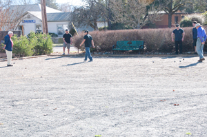
UP Fig 36 Pétanque
(Wiki)
court between the observatory and Observatory Ave.
Redwood
Empire Boules Club (UDJ
article)
|
UP Fig 37
The wheels are spring loaded, tension adjusted by screws
below.
Note screw in slot showing limit of motion.
|
UP Fig 38
View from above. Vernier microscope holder as about 7:00.
Two screw holes for another vernier microscope holder at
about 2:00.
|
UP Fig 39
The pully in center locks (CW) or unlocks (CCW) azimuth
movement.
|
UP Fig 40 3 of 7 package stickers
|
UP Fig 41 4 of 7 package stickers
|
UP Fig 42 azimuth locked CW
|
UP Fig 43 azimuth locked CCW
Knob at bottom center drives radial rod and clamps circle.
Works like clamp knob on vertical circle.
Knob above clamp knob is select/release (about 90 deg
motion) for latches at 0 and 180 degrees.
|
UP Fig 44 Close up of striding level scales
Hard to photograph, see UP Fig 49
|
UP Fig 45 Wiring for meridian (target)
light
(Wiki: Knob-and-tube
wiring) 1880 to 1930.
|
UP Fig 46 vertical circle missing two
levels. The central knob/pulley does not want to
turn.
Maybe because scope is resting on circle. Try again
when on mount.
|
UP Fig 47 Counterweight
It was thought that it was a box and that the two thumb
screws allowed opening the box to change the internal
weights. But that's not the case, the weight is a
single part.
The cover seems to only be a holder for the electrical
terminals and maybe the removable plate was made in
different weights as a fine adjustment for balance?
|
UP Fig 48 counter weight
|
UP Fig 49 striding
Level
one division is 2.2 arc seconds.

|
|
|
24 Feb 2015 Photos taken after
telescope is sitting on mount
It's not yet clear how the controls are used on the vertical
circle.
UP Fig 50 The 2 sensitive levels are
missing
level mounts are way off level.
|
UP Fig 51
 |
UP Fig 52
 |
UP Fig 53 There is
a Vernier scale for focus or to set scale scale factor for
the filar micrometer?
45 degree angle for pirsm (or mirror).
 |
UP Fig 54 The Vernier scale on both the
horizontal and
vertical circles is very faint.
Holder for scale viewing microscope is empty.
Magnifying glass and 45 deg reflector to light scale.
 |
UP Fig 55 Large handle loosens cap, you can
see the gap.
This allows moving the levels but not the telescope.
Notice holes in outer telescope tube for cooling.
Level mounts rotated to closer to level.
 |
UP Fig 56 This is a
fine control of the vertical angle of the telescope.
 |
UP Fig 57 Are the grooves the support
wheels run in
because of wear or were they put in from the beginning.
The roller on the right is jammed in the up position and
is
tipping the horizontal axis to the left. That's why
the adjusting
arm on the right has it's lower end to the right of where
it should be.
 |
UP Fig 65 Eyepiece hole (no eyepiece) but
with close focus
lens engaged as used to look at meridian targets.
|
UP Fig 66 Eyepiece
hole (no eyepiece) but with close focus
lens disengaged as used to look at stars. This way
no change is needed to any of the star viewing settings.
 |
UP Fig 61 Main clamp. Knob on back side
moves the central
rod to clamp telescope to horizontal axis. Once
clamped screw allows adjusting angle.
There's a similar rod and clamp knob for the horizontal
circle.
|
Fig 73 Adjustment bolts at right top and
bottom work
against each other to control height of Wyes on one side
to match height of Yye on other side.
|
Fig 70 Left side support wheels
The marker screw is at bottom of slot, but wheel is
holding
axle up off of Wye. Needs adjustment.
|
Fig 71 Right side support wheels
Bottom screw not run in to take up more weight, yet.
|
|
Zenith Telescope Procedures
Calibration
The Striding Level is used to adjust the three feet of the
mount to plumb the mount. Done by rotating the telescope.
The horizontal circle zero is set by sighting the North star
(Wiki) at a time when it's true north. This happens at two
times each day that are 12 sidereal hours apart.
There's a good chance that it can be done in the daytime.
The horizontal motion stops need to be set so that the scope is
in the North - South meridian when at either stop by sighting
the North Star at the correct time.
Then the meridian house targets need to be adjusted so that they
are each on the meridian. Once this is done the horizontal
circle is typically not read, the scope is used either to the
West or to the East of the pier at a stop.
Horizontal Movement
To make a horizontal move the clamp screw is loosened.
See UP Fig 16 for the knob at the top
center of the mount. The scope rotated 180 degrees.
Vertical Movement
When the arm clamp screw, see UP
fig 61 is loosened the telescope is free to be moved up or
down and if the vertical circle is clamped, see UP Fig 55 then the vertical circle moves
with it.
Measurement
So the procedure to move to a new star would be to:
- Zero the filar micrometer
- loosen the vertical circle clamp and set the V. circle to
the next star's declination.
- clamp the vertical circle.
- unclamp the telescope and center the two sensitive bubble
levels. This will get you within about 10 arc seconds of
the correct location and the star should be visible in the
finder within some TBD time prior to the scheduled meridian
crossing.
- As the star is getting near crossing, the fine vertical
position knob, see UP Fig 56, is
adjusted to bring the star to the center hair of the filar
micrometer.
- Press a button to log the sidereal time of meridian crossing
- read the two sensitive levels to correct the vertical circle
setting that was made initially.
- loosen the horizontal clamp (UP
Fig 16), unlock the latch, rotate the scope horizontally
180 degrees, set the latch and set the horizontal clamp.
At this point the scope will be at the same declination as
before only on the other side of the meridian.
- as the second star of the pair comes into view only the
filar hair is moved.
- Press a button to log the sidereal time of meridian
crossing.
- Record the filar setting and the two sensitive level
readings.
- get ready for the next star pair.
Stars are measured in pairs where one star will be on the North
side of the zenith and the other will be on the South side of
the zenith.
There is two ways to do it, for example the star that's North of
the zenith could be measured with the telescope on the East or
the West of the pier and the other star in the pair measured by
rotating the scope 180 degrees about the vertical axis.
Is it always done the same way or done differently on different
days?
1982 Photos
These photos were taken at the time the telescope was being
packed in order to ship it to the Smithsonian for storage.
From the Estate of David Pettey, Ukiah
Latitude Observer 1972 to 1982
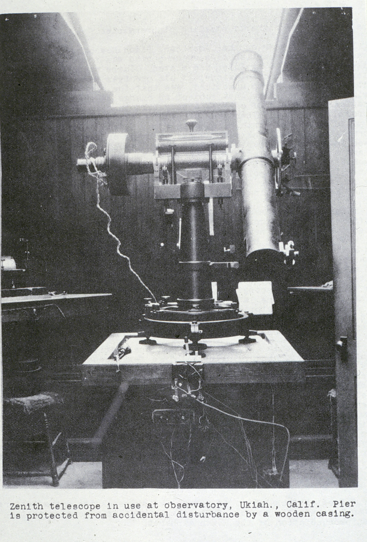
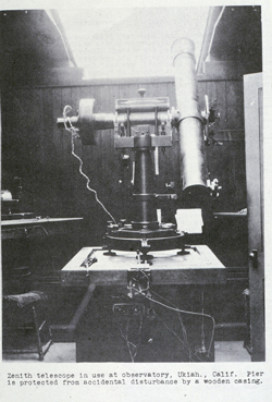
1982 Fig 1 "Zenith telescope in use at
observatory,
Ukiah, Calif. Pier is protected from accidental
disturbance by a wooden casing."
SPDT knife switch near electrical box.
What does it do?
In later photos appears to be an on/off switch,
which would be for lamp house.
|
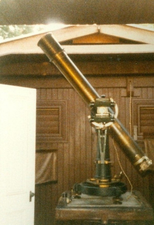
1982 Fig 2
 |
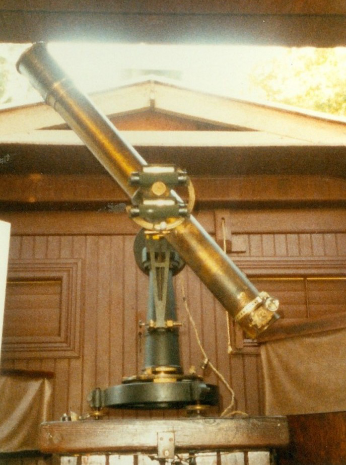
1982 Fig 3 Note plumbers tape holding
something
near eyepiece. What is it?
 |
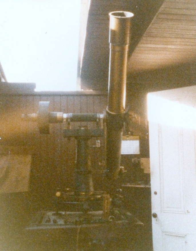
1982 Fig 4
 |
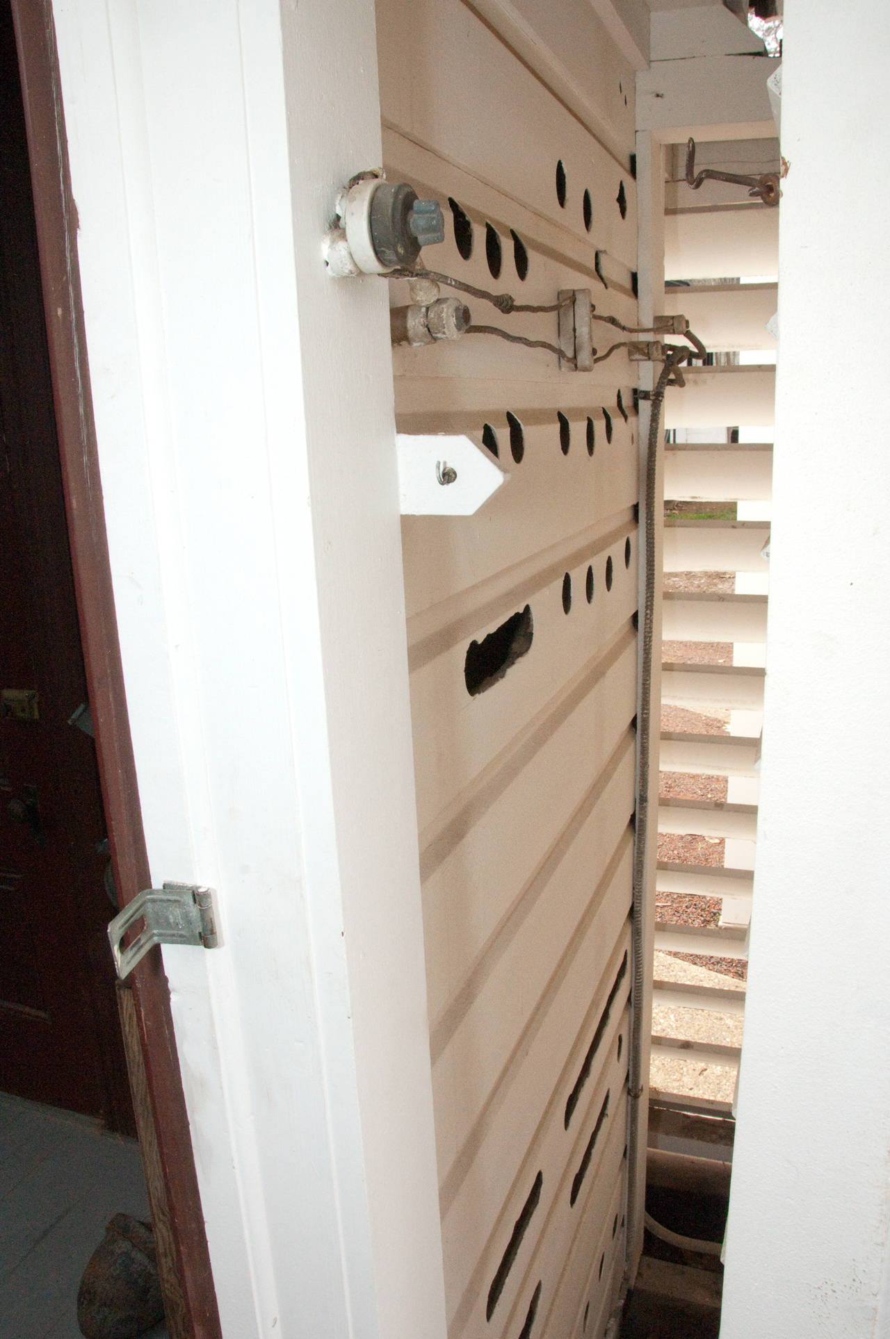
1982 Fig 5 Wiring for lamp house
Recording thermometer (barometer?) at left on wall.
 |
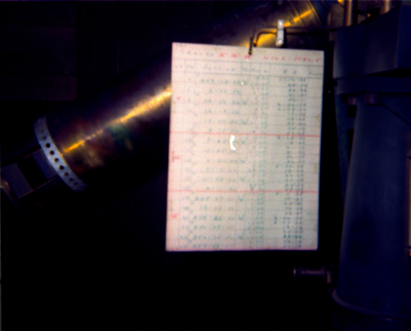
1982 Fig 6 List of star pairs
So far I have not been able to get this list.
 |
1982 Fig 7
 |
1982 Fig 8
 |
1982 Fig 9
 |
1982 Fig 10 Note vernier reading
microscope.
 |
1982 Fig 11 Rods form cage around striding
level.
 |
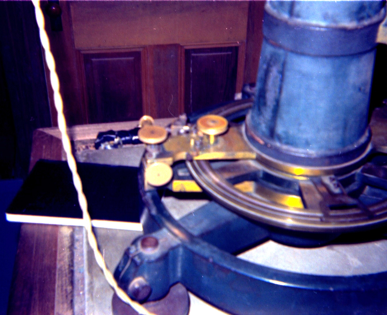
1982 Fig 12 Mount, after scope removed.
 |
1982 Fig 13 Note: (metal?) disks where
mount sits.
Bakelite on/off switch for lamp house.
Mount on floor at right.
 |
|
|
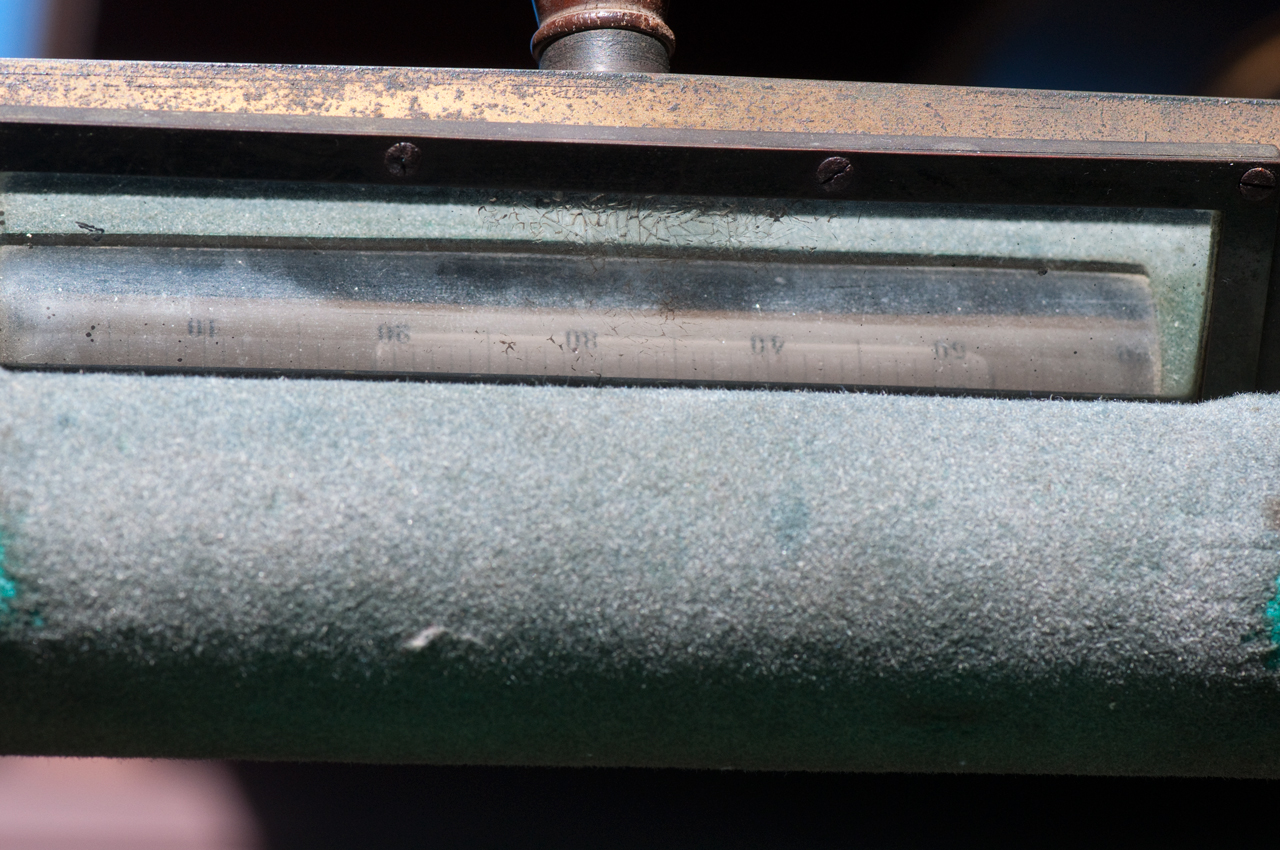
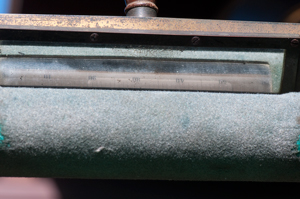
Striding Level
Fig 49 Striding Level
one division is 2.2 arc seconds.
|
Fig 64 Striding level numbers every 10
divisions.
bubble is 33 divisions long
|
|
|
|
|
This is the most sensitive level and sits at right angles to
the vertical axis of the mount. It is used to plumb the
vertical axis of the mount by adjusting the three leveling
feet and rotating the mount about it's vertical axis.
Note that part of the calibration process is centering the
bubble in the striding level relative to it's feet. This
can be checked by turning the level 180 degrees and seeing if
the bubble remains centered.
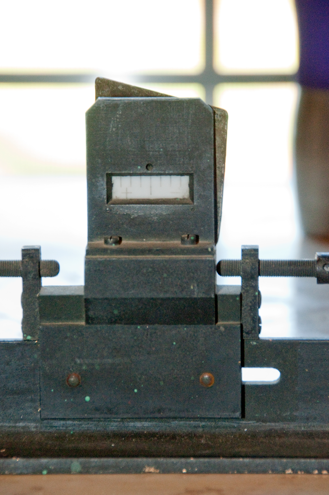
One division corresponds to about 2.2 arc seconds of angle.
Ref: Science, Vol XXIII, No. 593, 1913 pg 756 "The California
Earthquake at Ukiah", by Sidney D. Townley. The last
paragraph of this article mentions that the latitude levels
have a sensitivity of 1.0 (with no units specified, but I'd
assume that to mean 1 arc second per division, but that's
strange since this pair of levels are smaller than the
striding level.
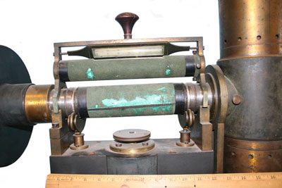
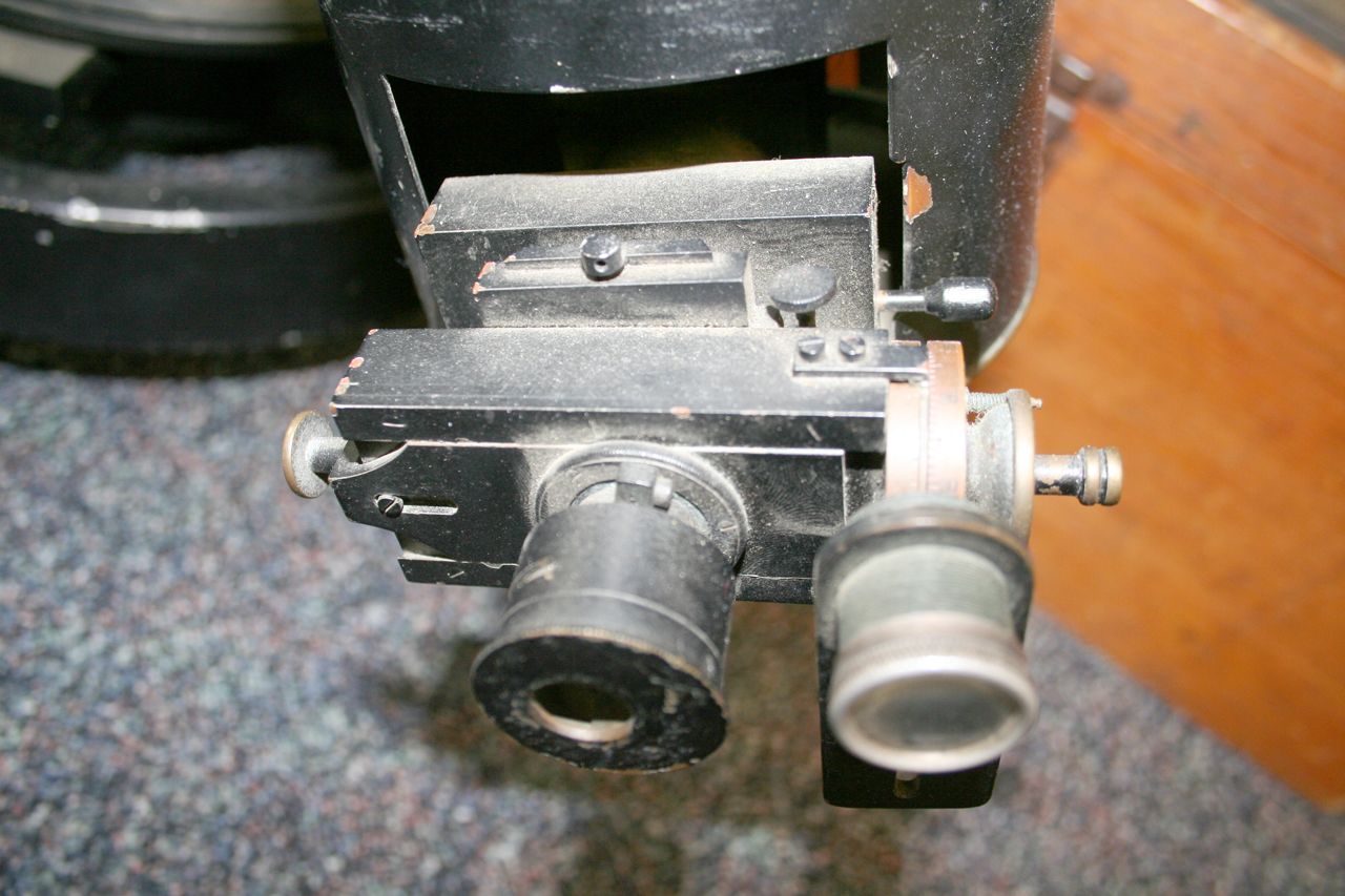
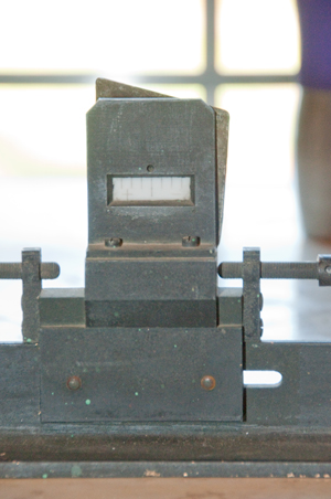
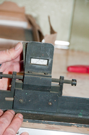
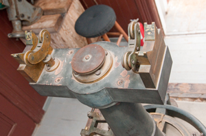
Filar Micrometer
This eyepiece coupled with the the pair of levels on the
vertical circle are the key elements in making the star zenith
angle measurement.
As of Feb 2015 we have not received this as well as a number
of other items this size and smaller.
A method was developed to check the repeatability of the
filar mechanism by taking readings on each division of the
targets in the meridian house.
Photos of another filar micrometer courtesy of the City of
Ukiah taken on the East Coast.
A Method for Determining the value of an average space of a
latitude-level in terms of a micrometer-turn by Frank
Schlessinger, 1901 shows that one micrometer turn is 40 arc
seconds on angle. Based on meridian star observations
and the telescope levels.
Fig EP 1 this one has a magnifying glass
built in.
Photos of the Ukiah observatory show a hand held
magnifying glass

|
EP 2
|
|
|
|
|
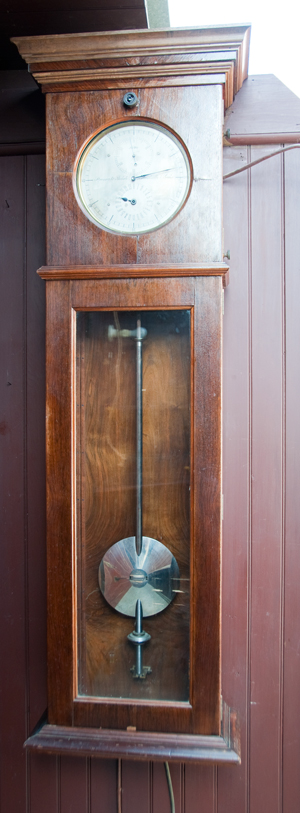
Clock
Most clocks tell time based on the Sun, where at true Noon the
clock shows 12:00. A sundial would show some time within
plus or minus 15 minutes of the actual time because of the
Equation of Time (Wiki)
and because the sundial may not be located on the centerline of
the time zone.
Sidereal time is based on when a star (other than the Sun)
crossed the local meridian (Wiki)
at midnight. The rate of a clock telling sidereal time is
slightly faster than a clock telling civilian time. In the
case of a pendulum clock the rate can easily be set to sidereal
by moving the pendulum up from it's normal position. The
rate can be checked by noting that when a given star crosses the
local meridian should be the same sidereal time every
night. The location of a star (Wiki)
is specified by it's Right ascension (Wiki: RA)
and Declination (Wiki).
The RA can be specified as an angle between 0 and 360 degrees,
or as hours: minutes: seconds of sidereal time.
So the astronomers can regulate the rate of their clock by
checking what time each known star crossed the local meridian,
but also can set their clock because the right ascension of all
the stars they are looking at is known and
tabulated.
A Local Mean
Sidereal
clock is used to know which stars are on the local meridian.
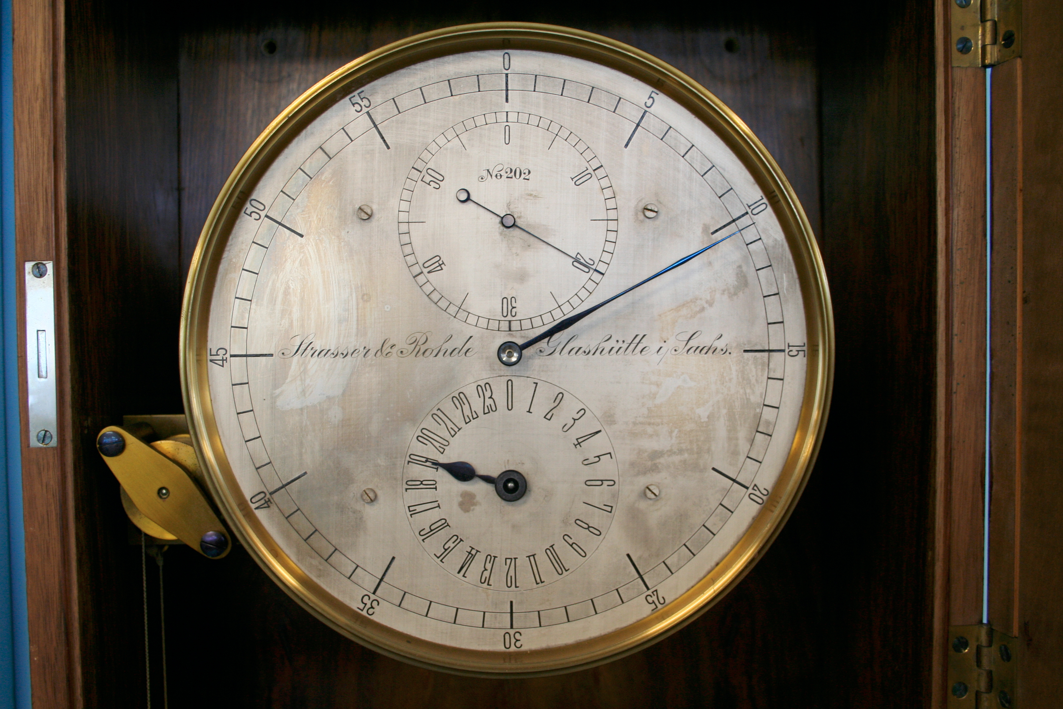
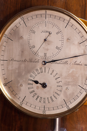
Strasser & Rohde 599 (
German
collector web page) most likely an Invar rod pendulum with
temperature compensation with lens shaped bob.
The small top hand is seconds, the sweep hand is minutes and the
bottom hand is a 24 hour hand. Set to run at sidereal time
not standard time. The purpose of the clock is to know which
star will be visible next. The clock would have an
electrical switch that would close for a short time once each
second used to make seconds ticks on the drum chronograph.
Later the
Heathkit
Most Accurate digital clock was used (photo in old local
newspaper at Historical Society). Note that the clock is to
tell the astronomer approximately when a star needs to be observed
and then to record the actual meridian crossing time as well as
zenith angle. Note that the position of the stars was not
well known then because no observatory knew it's latitude because
of the precession (
Wiki,
axial
precession) and wobble of the Earth (Wiki:
Chandler
Wobble,
Polar
Motion). By having all the latitude observatories
observe the same star pairs the location of those stars could be
refined. Note of each star pair one star was to the East and
the other to the West of the meridian.
Sidereal Time (Wiki)
Sidereal time is based on star meridian transits instead of solar
transits which are used for standard time. Since both are
based on an observer on Earth the difference between the two time
scales is exactly one day per year since the Earth is revolving
around the Sun and it's own axis.
Local Sidereal Time (
Wiki)
is adjusted for the longitude of the telescope.
The location of a star is commonly specified by it's Right
Ascension (
Wiki)
and declination (
Wiki).
The R.A. is the local sidereal time when the star transits the
meridian.
So for a night of observations there will be a
star list ordered in R.A.
For example the star Vega is a magnitude 0 star R.A.
18:27:12, dec 37 deg 47 min 18 sec North so when the
sidereal clock says the time is 18 hours 27 minutes and 12 seconds
it will be very close to directly overhead in Ukiah, CA. On
21 June 2007 at 1:54:32 local time Vega will be very near the
zenith. It's expected zenith angle will be 0 deg 29 min 0
seconds and to the South of the meridian.
Unpacking
Clk Fig 1 Face
Time shown: 19 hours (bottom hand), 12 minutes (long hand
off right side), 36 seconds (top hand).
|
Clk Fig 3 Clock was shipped with pendulum
attached.
Might have been better to remove it for shipping.
an example of damage
done by pendulum.
Two holes at left and right just above top of dial used to
anchor clock to wall.
|
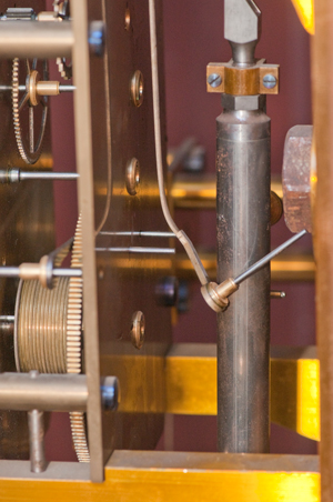
Clk Fig 5 The arm that couples the pendulum
to the escapement
appears to be bent.
|
Clk Fig 6 Key still in shipping wrap.
|
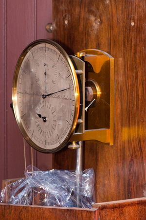
Fig 7 Clock on Wall
Pendulum has: main adjustable bob,
smaller adjustable lower bob,
Weight shelf near top with up/down adjustment.
Cage at bottom locks pendulum at center.
|
|
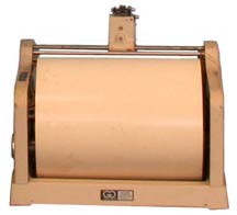
Chronograph
This is just a drum with a length
of paper. The drum turns at some known speed and when a
button is pressed when a star crossed the meridian a mark is
made on the drum. The sidereal clock makes a tick mark on
the drum once each second. So that sidereal time when an
observation was made can be determined. Since the right
ascension of a star is a fixed number there are a small number
of reasons that the observation would not be at the exact time
of RA.
- A blunder where the wrong star was observed
- the clock is either not set correctly or is running at the
wrong rate
- the longitude of the observatory has changed
Note that the drum speed does not matter.
4 Jun 2009 - The NOAA May 1977 paper on polar motion mentions
that the latitude observatory data was used to see if they
changed longitude. That implies that the time of meridian
crossing was recorded. Up until the mid 1960s that could
be done using the Western Union time service (see my
Self Winding Clock Co web
pages) and after the mid 1960s by using
the
Heathkit GC1000 radio
clock. Since neither the WU time service nor the
Heathkit GC1000 are sidereal
time pieces they would be used to set the local pendulum clock
which might have kept sidereal time. Or, if it kept
regular time a mathematical conversion would be made.
After reading Circles, Clocks, Ships, and Wires: Meridian
Circles within Innovative Assemblages in 19th-Century America
(Ref 7) looked for patents on recording chronographs. They
were used for seismography, tide gauges and many other
applications.
|
816767
Chronograph, Meyer
Wildermann, Robert
Ludwig Mond, 1906-04-03, -
This may have been used with a seismometer.
|
|
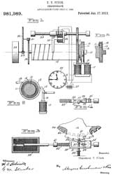
981989
Chronograph, Theodore T Fitch, 1911-01-17, -
The drum allows comparing pulse per second hacks from
master clock with event hacks.
Very similar to the application at the observatory.
|
|
1376890
Chronograph, Alfred
L Loomis (Hw Clocks, Wiki),
Paul
E Klopsteg (Wiki),
Paul
G Agnew, Winfield
H Stannard, 1921-05-03, - capacitive discharge
through step up coil causes spark to make pinhole in
paper record. The application is measuring the
speed of a projectile, i.e. ballistics.
|
|
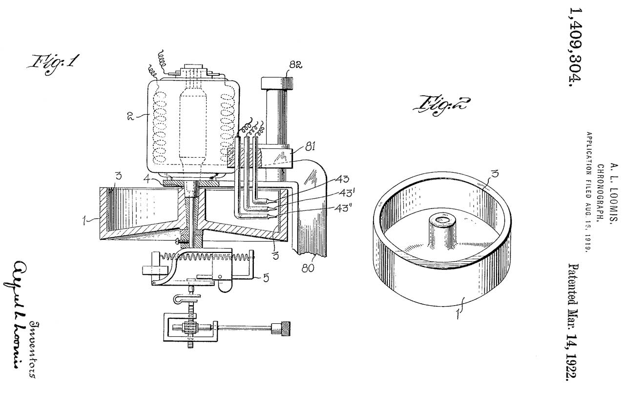
1409304
Chronograph, Alfred
L Loomis (Hw
Clocks, Wiki),
1922-03-14, -
|

|
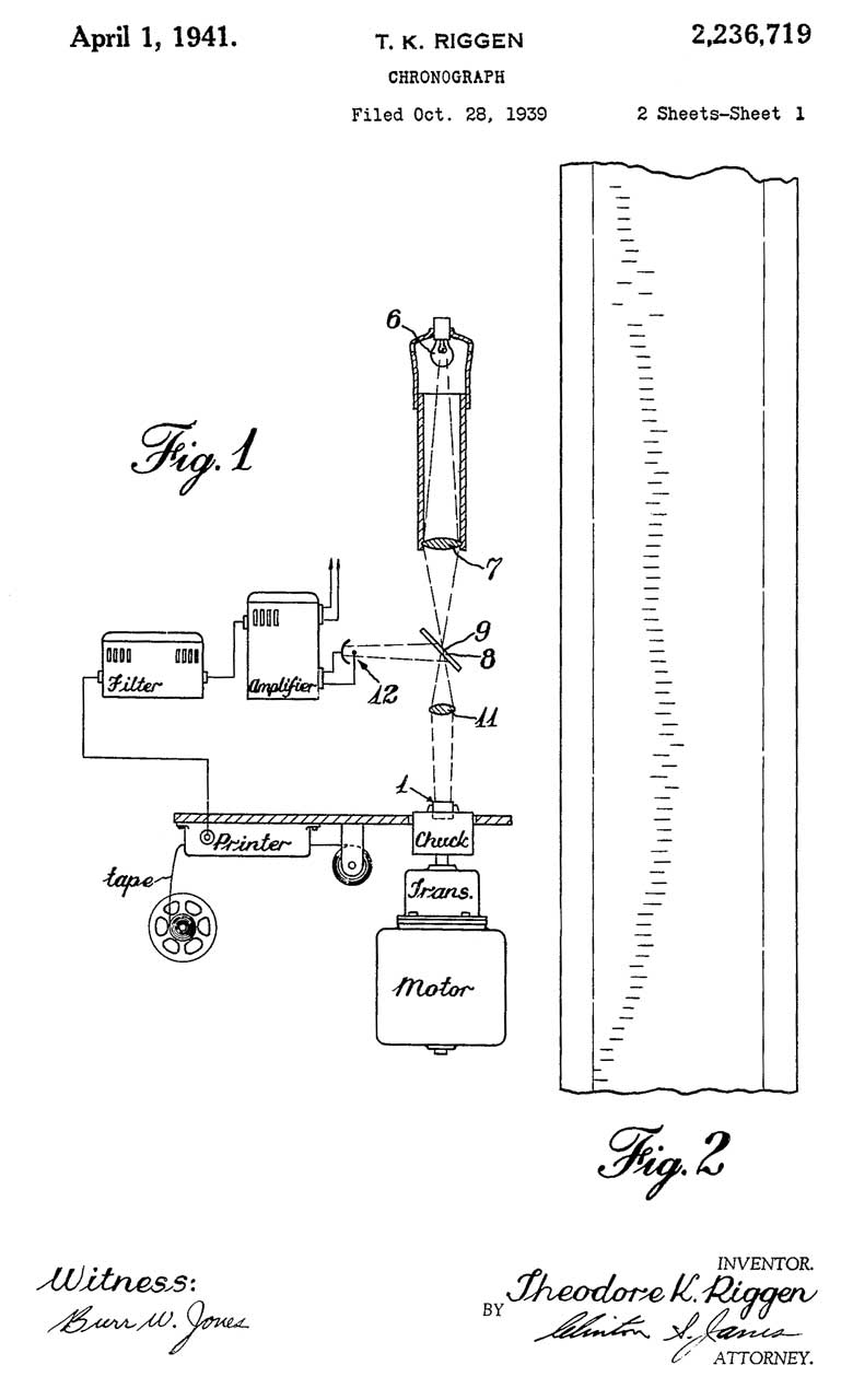
2236719
Chronograph, Theodore
K Riggen, Bendix
Aviation, 1941-04-01, - for testing weapon
clockwork fuzes.
Uses paper tape instead of a sheet of paper on a
drum. Most likley paper tape from a teletype
machine.
Riggen holds a number of related patents.
|
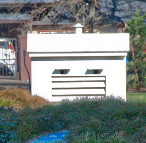
Observatory Building
The buildings for all the latitude
observatories may be the same (very similar) in design. In
any case the Ukiah building and the Gaithersburg were made from
the same set of plans but the as built configuration was
different and changed over time.
A large part of the building design relates to how it cools when
the roof is rolled back and how it heats during the daytime when
the roof is closed. This is extremely important since
thermal gradients will effect the accuracy of the
telescope. There was a thermometer on the wall of the
observatory and a chart for converting between F and C.
Measurements would not be made until the equipment temperature
stabilized.
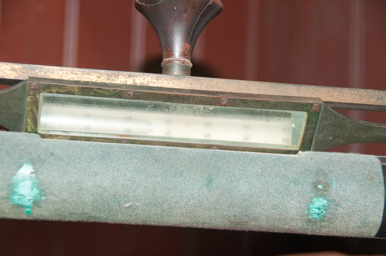
Thermometers
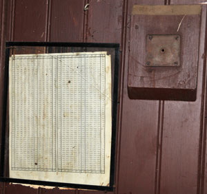
In the observatory.
The bracket probably held a thermometer and to it's left is a
conversion chart between F and C. The chart was not typed
with the minus signs, but they have been added by hand. It
also is missing the decimal point for the tenths of a degree C
making it awkward to read. There were also thermometers
outside on either side of the building that were recorded at about
the center of the observation run each night.
Photo by PaulK 30 May 2009
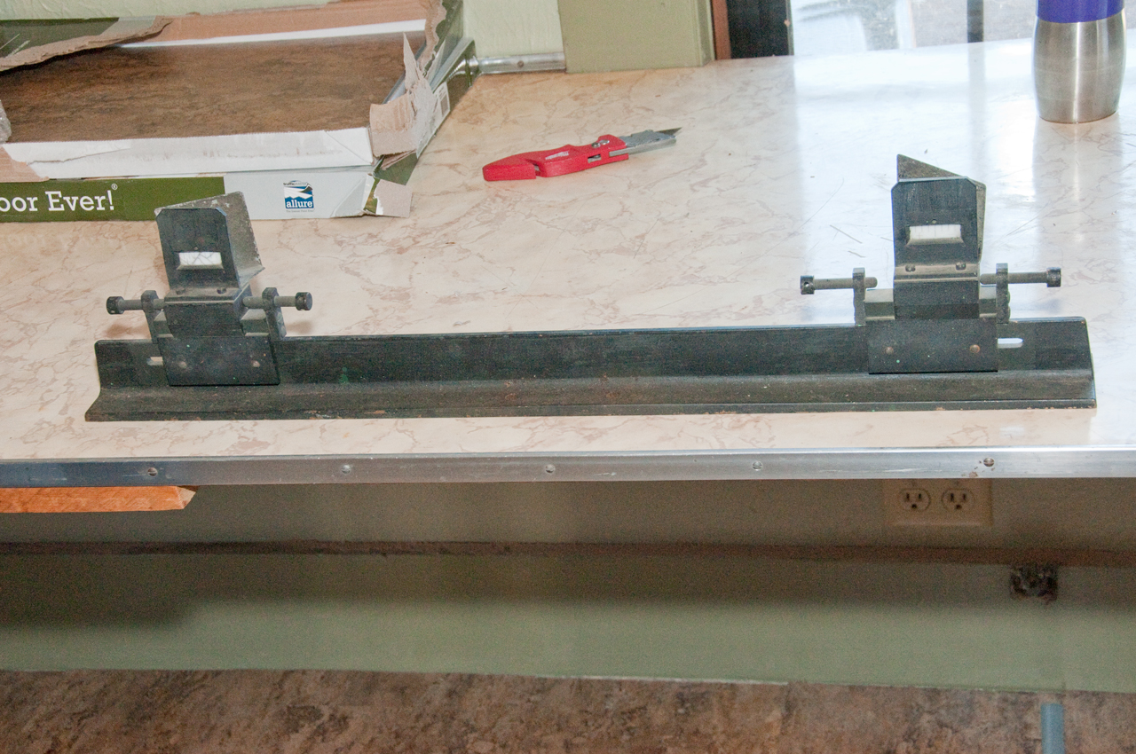
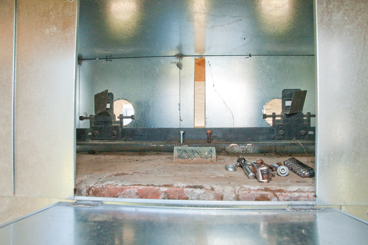
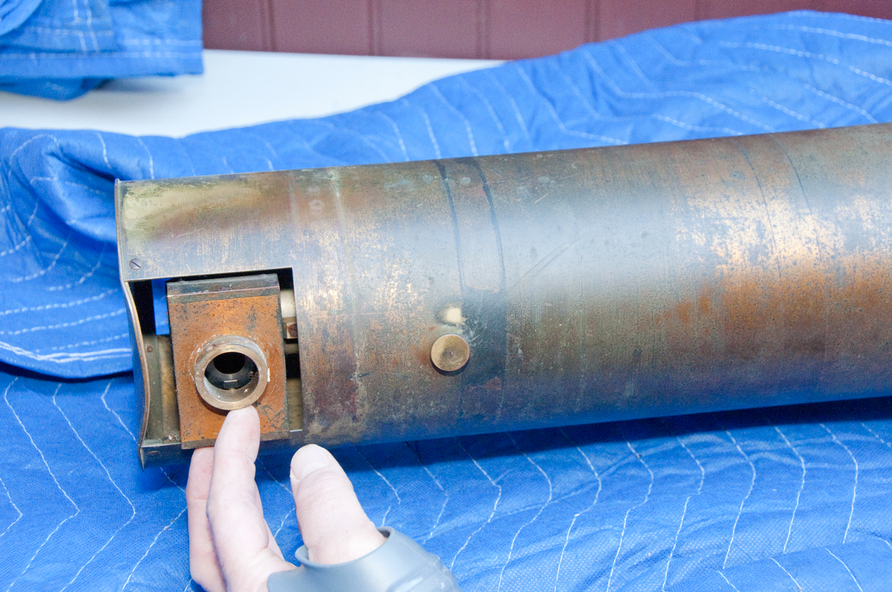
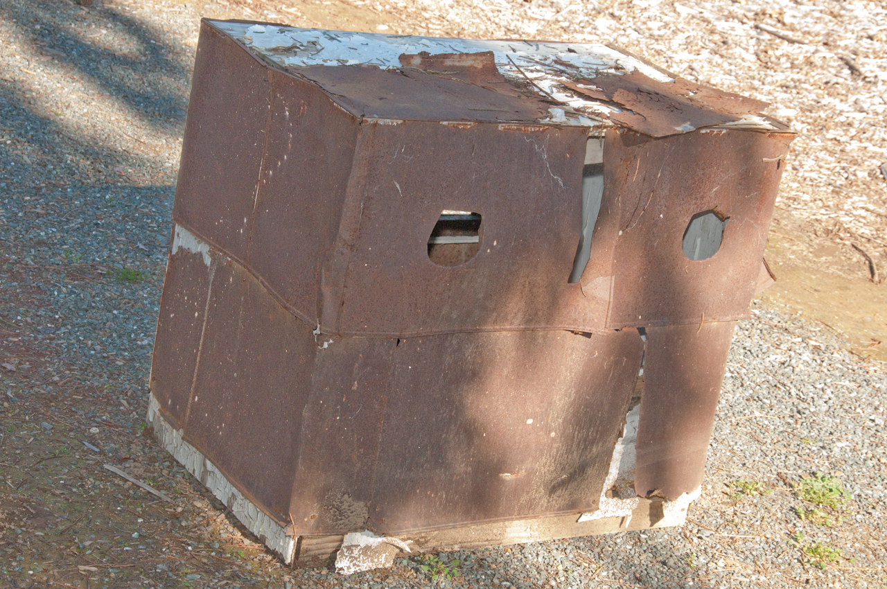
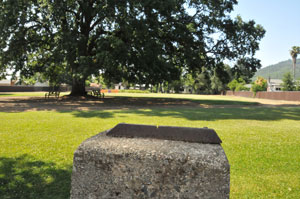
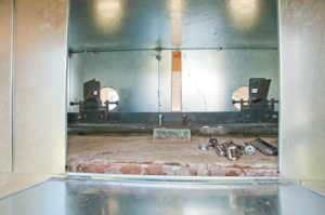
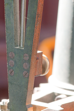
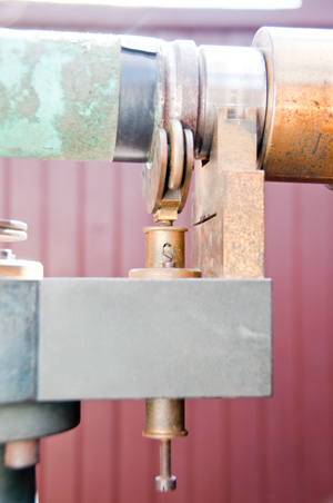
Target Building (aka Meridian Alignment
Building)
Exactly North of the zenith telescope are a pair of
targets. They are sitting on a masonry pier that's about
three feet on a side and four feet tall. The masonry is
surrounded with a sheet metal box with a hole for each of the
targets, a vertical slit between the targets (reason unknown)
and a vent hole at the top which would be necessary for the
carbide lantern which was the first light source, but not
needed when they switched to an electric lamp.
The purpose of the targets is to zero the azimuth (North)
direction. By using two targets the telescope can be set
to North when it's on either side of the mount.
As seen from zenith telescope
|
Target bar sitting on bench.
There are two translucent scales with ruler marks.
Behind each scale is a light reflector at about 45
degrees to
back light the scales using either the early calcium
carbide
lantern (Wiki)
or the soon to be installed electric light in the
center.
The sheet metal may be been there to prevent fires?
|
Original sheet metal box
|
Target bar sitting in house.
|
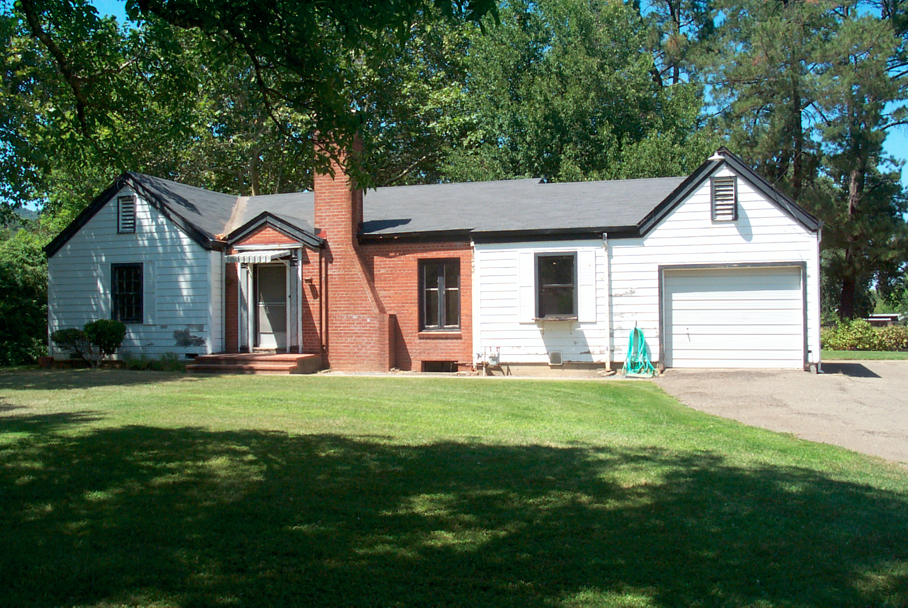
Office Building (aka Interpretative
Building)
Sidney D. Townley (
Wiki)
was the resident astronomer at the Ukiah Latitude Observatory on
April 18, 1906 and felt the San Francisco earthquake. I'm
guessing it made a big impression on him because when his
assignment at Ukiah was up he moved to Stanford University and
in 1911 was one of the founding members of the
Seismological Society of
America acting as the editor of their key publication.
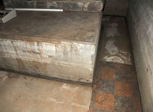
In the basement
of the astronomers house there's a room maybe 16 by 14 feet and
in the rear corner of the room the top of a concrete block
about 8 x 8 feet on a side is sticking up from the floor
about two feet. There is a gap between the concrete mass
and the building floor to isolate it. It was used for
developing seismometers. (Photo by PaulK 30 May 2009)
H. G. WROCKLAGE,
Installation of McComb-Romberg tilt-compensation
horizontal-component seismometers at the International
Latitude Observatory, Ukiah, California
Bulletin of the Seismological Society of America,
January 1, 1934; 24(1): 69 - 71.
Arnold Romberg (
Univ.
of Texas)
"The concrete peir is 6-1/2 x 8 feet base by 5-1/2 feet high,
the base being three feet below the normal surface of the soil."
patent
2293437
Force Measuring Device, Aug 18, 1942 " zero-length spring"
Provisional result of the work of the international latitude
service in the North Parallel + 39° 8’ during the year 1933
History
of the Seismological Society of America -
My
seismometers web page.
STA      LAT      LON 		ELEVATION 	STANAME
UKI      39.1372  -123.2106     0.199 Ukiah, 	NEIC
Is this the  Latitude Observatory?  The Lat is the same (39.1372 vs. 39.137294) so yes.
The USGS shows UKI as an open seismic station, probably a typo.
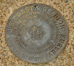
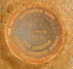
Magnetic Repeat Station
The Plot Plan shows a number of survey markers that suggest that
a Magnetic Repeat Station was located at the observatory
site. There are magnetic observatories where the
instrumentation is permanently installed and there are repeat
stations where the instruments are brought to the site once
every few years.
IAGA
Guide for Magnetic Repeat Station Surveys, by L.R. Newitt,
C.E. Barton, and J. Bitterly, 1997, ISBN: 0-9650686-1-7 -
Note because the latitude observatories were probably the places
on Earth where their location was known to an extremely high
precision I expect they would also be home to other scientific
investigations where they need to know the location.
I would have expected there to be a GPS reference station here,
but that's not the case.
Plot Plan
The plot plan made in 1991 shows the
boundaries, North-South direction and a number of
survey markers.
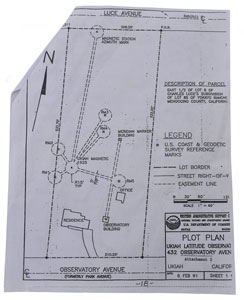 |
Magnetic
Station Azimuth Mark
|
RM 3
KT2024
|
Meridian House (being restored)
Marker
Brick masonary pier under blue plastic.
|
USGS
Magnetic Station
|
RM4C
|
RM5 NGS
Data Sheet
PID
- KT2010
|
RM1
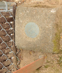
|
Magnetic
Station Azimuth Mark
|
|
|
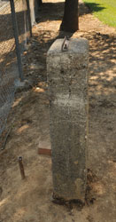
The Northern most marker is a concrete post with an angle iron
bracket at the top and labeled "Magnetic Station Azimuth Mark".
This establishes true North by using the main magnetic
monument. They are about 100 meters (328 feet) apart.
Much further than the distance between the observatory and the
meridian target separation of about 180 feet.
Note that along a North-South line through this marker is the
"Ukiah Magnetic 1925" marker and a notation showing a fifteen foot
nominal radius. There are 5 other survey markers all
radiating out from the Ukiah Magnetic 1925 marker labeled: RM1,
RM2, RM3, RM4 and RM5. Maybe for Relative Magnetic?
Marker photos by PaulK.
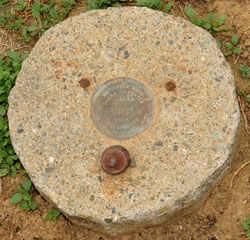
NGS Data Sheets at the Ukiah Latitude Observatory
PID
---------
KT1197
- NAD 83(1986)- 39 08 15.06464(N) 123 12 43.35952(W) AD(1984.00) 2
STAMPING: 651.928 B 105 1932
The magnetic marks are listed on this data sheet.
KT1198
- NAD 83(1986)- 39 08 14.10437(N) 123 12 42.15978(W) AD(1984.00) 3
The top
and extreme northwest corner of the concrete base supporting the
zenith telescope and about 4 feet above the floor.
PID    Reference Object                     Distance      Geod. Az
                                                          dddmmss.s
KT2010 UKIAH MAGNETIC AZ MK                 99.828 METERS 00000
	NAD 83(1986)-  39 08 18.30181(N)    123 12 43.35939(W) AD(1984.00) 2
KT2024 UKIAH MAGNETIC RM 3                  42.632 METERS 01959

KT2023 UKIAH MAGNETIC RM 4                  31.887 METERS 02829


KT2025 UKIAH MAGNETIC A POINT               29.822 METERS 10237


KT2011 UKIAH LATITUDE 1925                  41.413 METERS 13547


KT2001 UKIAH MUNICIPAL AIRPORT BEACON ON H APPROX. 3.0 KM 2223614.1


DB6008 UKIAH MAGNETIC RM 1                  15.193 METERS 22349


DB6009 UKIAH MAGNETIC RM 2                  15.925 METERS 30730
Community Facility
Some years ago the grounds were developed with a walking path
and native plant maze. On Saturday 31 Jan 2015 when there
to take photos of the unpacking of the telescope there were
maybe a dozen groups of from 1 to 4 people walking, walking
their dogs, exercising or playing Pétanque
(similar to Bocce ball Wiki)on the
grounds.
Talcott Method
Talcott's method took into account that the star catalogs then
available (maybe a hand full) had errors for some stars. By
observing a group of stars (maybe a couple dozen) in a night and
by pairing the stars so that one was North of the zenith and the
other was South of the zenith not only instrument errors but also
star catalog errors could be detected and corrected.
The same star list was used by all the observatories. This
allows for further error detection and reduction and is why all
the latitude observatories are very close to 39:08 N.
The stars are in pairs where each star in a pair is very close to
the same zenith angle. The scope is set for the average
zenith angle of the pair using the vertical circle and vernier and
the scope is set East or West depending on which star culminates
first. When that star crosses the meridian the micrometer
eyepiece is set to measure how far from the central angle the star
is. Then the scope is revolved 180 degrees about the
vertical axis and when the second star crosses the meridian the
micrometer eyepiece is again used to read how far it is from the
central angle of that pair. The micrometer readings are much
more accurate than an angle read from the vertical circle and is
the key benefit of the Talcott method.
Description of observation using Talcott method from Leaflet No.
111 - May 1938, The Variation of Latitude by William F. Meyer, UC
Berkeley
By this method the latitude is determined by observing
with a micrometer the difference between the nearly equal zenith
distances of two stars which pass the meridian within a few
minutes of each other, one north and the other south of the
zenith. The Zenith telescope is set to the proper zenith
distance for the first star with the bubbles of the delicate
level, which is attached to the telescope, adjusted and read.
After the star has been observed, the telescope is reversed on
its vertical axis without altering the position of the level.
The telescope can now be adjusted to point to the same zenith
distance as used for the first star. Since the stations have
nearly the same latitude, the same stars can be used at each,
thus assuring homogeneous results.
Equation
From Popular Science Monthly, Vol LXXV, No. 5, Nov 1909.
Φ = ½(δn + δs)
+ ½(mn - ms)*R + ½(ln
+ ls) +½(rn - rs)
where:
subscript s means to the south, and n to the north
Φ = latitude
δ = measured star declination from vertical circle
m = micrometer measurement
R = micrometer to angle conversion factor
l = reading of vertical circle levels
r = refraction correction as
a function of telescope zenith distance
If the two stars are at exactly the same
declination δ and the instrument is
reversed without disturbing the pointing, then the m, l and r
terms become zero and the latitude becomes δ
star zenith angle.
Note the declination (Wiki) of
a star is measured the same way as latitude. So for an
observer on the equator looking at a star with zero degrees
declination would look straight up, zenith angle of zero.
For an observer at 39 degrees North a star with a declination of
39 N would be straight up.
Need to determine how the vertical circle is calibrated.
Is straight up zero or can it be set to 39:08?
Weather
In the same Popular Science article referenced above on the
equation there is a discussion about the impact of weather and
incomplete measurements.
Historically, averaged over all the observatories, on 46.5% of
the nights there is good weather. The odds of all six
observatories to have good weather on the same night is about
one in a hundred.
When making a measurement on a given star if a mistake is
made you can not turn back the sky and make the measurement
again, it's a missed measurement.
Although Ukiah averaged about 60% of all possible measurements
the other observatories were not that good and they averaged
about 50%.
So the odds of measuring all the stars at all stations on the
same might are about 1/4096. Estimated once every 20
years.
Star List
Twelve groups of stars (I to XII), each containing eight
pairs total. Six latitude pairs not more than 24 degrees
from the zenith and two refraction pairs about sixty degrees
from the zenith were selected for observation. Eight
pairs per group total. Each star in a latitude pair is
within 16 minutes of arc and the refraction pairs are within 5
minutes of arc [Ref ASoP1899]. So the filar micrometer may have a
range of plus and minus 20 minutes of arc?
The brightness (astronomical magnitude (Wiki,
my magnitude
web page) ranges from 4.0 to 7.4. Note the common
navigation stars are much brighter (Wiki).
The time interval between culminations vary between 4 and 16
minutes.
Ref: letter of 11 April 1947 from DOC to Miss Marian R.
Marvin, Librarian, Ukiah Public Library.
fact check: 24 hours (1440 minutes) divided by [ (12 groups *
(6 pair + 2 pair) *2= ] 192 stars = 7.5 minutes between stars
on average.
As of Feb 2015 I'm still looking for the list, but did find
out a little more about it from the article:
[Ref ASoP1899] Program for the International Geodetic
Association for Observing Variations in Latitude by
Frank Schlesinger, Publications of the Astronomical Society of
the Pacific, Nov 20, 1899.
The refraction (Wiki)
pairs allow determining if a anomaly is caused by refraction
(the effect gets larger as a star gets closer to the horizon)
and a parallax error which would be the same for observatories
on opposite sides of the Earth.
Group
|
R.A.
|
From
|
To
|
Duration
|
Overlap
|
I
|
0h
- 2h
|
Sep 23
|
Dec 6
|
74
|
na
|
II
|
2h
- 4h |
Nov 2
|
Jan 4
|
64
|
35
|
III
|
4h
- 6h |
Dec 7
|
Jan 30
|
55
|
29
|
IV
|
6h
- 8h |
Jan 5
|
Feb 24
|
51
|
26
|
V
|
8h -
10h |
Jan 31
|
Mar 21
|
50
|
25
|
VI
|
10h
- 12h |
Feb 25
|
Apr 15
|
50
|
25
|
VII
|
12h
- 14h |
Mar 22
|
May 11
|
51
|
25
|
VIII
|
14h
- 16h |
Apr 16
|
Jun 8
|
54
|
26
|
IX
|
16h
- 18h |
May 12
|
Jly 9
|
59
|
28
|
X
|
18h
- 20h |
Jun 9
|
Aug 13
|
66
|
31
|
XI
|
20h
- 22h |
Jly 10
|
Sep 22
|
75
|
35
|
| XII |
22h
- 24h |
Aug 14
|
Nov 1
|
80
|
40
|
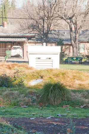
|
|
|
|
|
40
|
Dividing Engines (Wiki)
The quality of dividing engines may have been a factor in
choosing who made the telescope since the quality of the
vertical circle is the prime specification for this telescope.
Both the horizontal and vertical circles can be read directly to
10 arc seconds. The filar micrometer increases the angular
resolution maybe 100 times to 0.1 arc seconds.
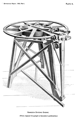
|
In order to mark a ruler or protractor with
divisions that are accurate some type of mechanism is
needed to eliminate errors caused by variations caused by
humans. Jesse Ramsden (Wiki)
developed a dividing engine 45" in diameter with 2,160
teeth (6* 360) on it's circumference. In order to do
that he also invented a screw cutting lathe using change
gears custom made to the pitch needed. Note: A
screw with notches filed into it was used to cut the big
wheel. Then the big wheel was measured and corrected
and then tested. Over a number of cycles of cutting
and measuring the quality of the dividing engine was
improved.
Note that the problem was getting a precise division of
the circle that then could be used to mark other circles.
The photo at left is from the Annual
Report of the Board of Regents of the Smithsonian
Institution, July 1890.
It was in 1890 that the Ramsden dividing engine was
donated to the Smithsonian.
The first 45" Ramsden dividing engine was made in 1775 and
was capable of dividing to 1/2 minute (30 seconds) of arc.
As part of his award from the commissioners of longitude
he made public his design not only for the dividing engine
but also for the screw cutting lathe that was needed to
make the dividing engine.
A Ramsden engine was used to improve the 8 foot radius
scale on Halley’s
8-foot (radius) Iron Mural Quadrant at
Greenwich.
That web page shows a lot of similarity with the latitude
observatories.
As time went on the diameter of the circle needed to get a
specified accuracy (say 1 arc minute for the 45" Ramsden
engine, or 1 arc second for the 5" Wild T2 theodolite) has
decreased with time.
But I still need to examine the dividing on the vertical
circle of the zenith telescope to see how precisely it can
be read. See Figures below.
|
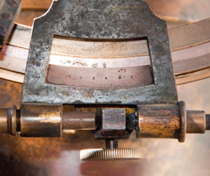
UP Fig 58 Vertical circle has numbers every
5 degrees.
Large divisions every 1 degree.
Small divisions every 10 minutes.
The vernier divisions are 10 arc seconds each.
Filar micrometer to read
finer angles.

|
UP Fig 60 Horizontal circle has numbers
every 5 degrees.
Large divisions every 1 degree.
Short divisions every 10 minutes.
The vernier divisions are 10 arc seconds each.
|
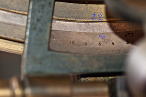
Close UP of Vertical vernier
Marked 10 8 6 4 2 0
(minutes)
Each minute is divided into 6 parts
each of which is 10 seconds
|
Progress of Astronomy by
William C. Winlock
In another article in the same 1890 report titled:
Progress of Astronomy by William C. Winlock there's
information about the Earth's latitude:
"The EARTH-Variat'ion of latitude.-The subject of the
change of terrestrial latitudes, to which allusion has
been made in previous reports, continues to receive
considerable attention from astronomers and geographers.
The following results have been obtained by Dr. Kiistner,
in continuation of his former researches, from 7 pairs of
stars at three different times of the year:
| Epoch. |
Latitude of Berlin. |
1884.32
|
+520 30'
16". 73-0.82dA |
| 1884.70 |
16.96"+0.83dA
|
| 1885.31 |
16.52-0.85dA
|
where dA represents the correction to the assumed
constant of aberration. The direct
inference from these figures is that in 7 months the
latitude of Berlin decreased 0".44. Polkowa showed about
the same time a similar change:
Epoch.
|
Latitude of Polkowa
|
1882.31
|
+59o46"18".52
|
1883.51
|
18".54
|
1884.70
|
18".63
|
1885.23
|
18".31
|
1885.31
|
18".30
|
a decrease of 0".33 from 1884.70 to 1885.31.
The general agreement of these results certainly calls for
further investigation; and to test the matter Mr. Preston
has been sent out by the U. S. Coast Survey, and Dr.
Marcuse by the International Geodetic Commission, to
Honolulu, which is at the opposite end of the earth's
diameter from Berlin, and by simultaneous observations at
these two stations it is hoped the question will be
settled.
It is quite possible that the origin of the apparent
change at Berlin in 1884-1885 is meteorological, a view to
which Dr. Foerster inclined in bringing' the matter before
the Association Geodesique in 1888. The whole question is,
then, whether there are changes in the disposition of
atmospheric strata sufficient to account for the facts
observed, or the axis of rotation and the axis of inertia
of the earth are not sensibly coincident.
A complete resume of the subject is given by M. Tisserand
in the Bulletin Astronomique for 8eptember, 1890.
Mr. Ricco has experimented with a somewhat novel
demonstration of the rotundity of the earth. At the
observatory of Palermo, which is situated at a distance of
1-1/4 miles from the Mediterranean and 236 feet
above sea level, a great number of photographs of the sun
reflected from the surface of the water have been taken a
few minutes after rising or before setting, and they show
that the diameter in the plane of reflection is less in
the reflected image than in the direct. This deformation
is due to the fact that the surface of the water forms a
cylindrical mirror, with axis horizontal and normal to the
plane of reflection. The amount of the observed flattening
accords well with that demanded by theory.
|
A back of the envelope calculation.
Vertical circle is about 9" diameter, 28-1/4"
circumference.
There are small divisions every 10 minutes.
There are 21,600 (360 * 60) minutes in a circle, or
2,160 each 10' small divisions.
28-1/4" / 2,160 = 0.013" between small divisions.
|
Vernier scale (Wiki)
I think the length of the vernier scale is 10 degrees
on the circle or 60 small (10 arc minute) divisions, or
600 arc minutes long. But a vernier scale divides
the smallest division by the number of of divisions on
the vernier so in this case 10 arc minutes (600 arc
seconds) are divided into 60 parts or 10 arc seconds per
division on the vernier.
The key idea is that a vernier divides the smallest
division on the circle by the number of divisions on the
vernier.
While the commonest vernier has 10 divisions, more can
be used, 60 in this case. In the case of a full
circle the vernier might be made to cover 1/2 or 3/4 of
the circle resulting in much higher resolution, but how
accurate would depend on the quality of the dividing
engine. Also the more divisions in the vernier the
longer it takes to read it.
|
Dividing Engine Patents
14082
Dividing Engine Dial, William H. Brown, 1856-01-15,
343980
Dividing-engine, Amos H. Brainard, 1886-06-22, - a fancier version
of the Economy
Indexing Jig.
398504
Dividing-engine, James B. Faucette, 1889-02-26, -
686266
Dividing-engine, Adolph
L De Leeuw, 1901-11-12, -
GB191117408
(eSpaceNet)
Dividing Engines or Machines for Marking Thermometer Tubes or for
the like purposes, Edgar T. Perken, Perken
Son & Co, 1912-07-25, - linear scale
1067682
Dividing-head, Oswald
Roessler, 1913-07-15, - integrated into milling head
1172778
Angular spacing and feeding mechanism for dividing-engines and
machine-tools, Herman
W Falk, Percy
C Day, Falk
Co, 1916-02-22, - for gear cutting machines
1206006
Dividing apparatus, Johan
Oscar Lifflander, J
& Cg Bolinders Mek Verkst AB, 1916-11-28, - a version of
the Economy
Indexing Jig.
2487314
Indexing device for optical projection comparators, Roger
E Coles, IBM,
1949-11-08, -
2524538
Indexing device, Alan
H Pearson, Pearson
Inc, 1950-10-03, - more accurate and easier to use on
milling machine.
2610551
Indexing device, Frederick
W Riedel, United
States Steel, 1952-09-16, - a version of the Economy
Indexing Jig.
2723461
Roundness measuring and/or recording apparatus, Reason
Richard Edmund, Rawstron
George Ormerod, Taylor
Taylor and Hobson Ltd, 1955-11-15, - for measuring
roundness, not for indexing
2795973
Indexing device, Molitor
Arvid Axel, 1957-06-18, - energy management for faster metal
working
3072014
Photographic apparatus for producing curved lines, Rawstron
George Ormerod, Rank
Precision Industries, 1963-01-08, - "This invention relates
to an apparatus for manufacturing an optical cam device..."
The
Dividing Engine in History -
YouTube: Machine
Thinking: The HIDDEN Screws of
PRECISION, 19:53,
Coordinates of North Pole
Lunar Ranging
This is a modern part of determining the period of the
Earth's rotation as well as other astronomy. The idea is to
measure the time it takes a pulse of laser light to go from the
Earth based observatory to one of the retro reflectors on the Moon
and come back.
It turns out that, just like the latitude observatory, great care
is needed to make precision measurements. In the case of the
lunar ranging the Earth's gravity tides that cause the ocean water
level to move up and down also cause the bedrock at the top of
mountains to move up and down (Wiki).
Love Numbers (Wiki)
are a measure of how stiff the Earth is at a given location and
allow calculating how much it wall move as gravity changes because
of the Sun, Moon, &Etc.
There are a couple of ways to measure the movement of the
telescope used to make the lunar distance measurements:
1) precision GPS - but it also measures all the changes, not just
the change due to earth time
2) a gravity meter, like that GWR that's used for
the APOLLO system, allows correcting the telescope position to
account for the earth's tide.
3449956
Force
measuring instrument, Goodkind
John M, Prothero
William A, Jun 17, 1969, 73/382.00R, 73/514.18
5204568
Superconducting
bearing for borehole and survey gravimeters, Robert
L. Kleinberg, Douglas
D. Griffin, Richard
J. Warburton, Gwr
Instruments, Apr 20, 1993, 310/90.5, 33/366.11, 324/346, 73/382.00R -
Apache
Point Observatory Lunar Laser-ranging Operation (APOLLO)
The
Basics of Lunar Ranging
Wiki- Lunar Laser Ranging experiment
ScienceShot:
Decades-Old Soviet Reflector Spotted on the Moon
YouTube: Why this
observatory fires lasers at satellites, 3:16 -
Donated T. Cook & Sons, York Telescope
While taking photos of the unpacking of the zenith telescope I
discovered a donated mount (see UnPacking
Fig 32 above). Martin Bradley posted photos of these
parts on the Antique
Telescope Society Yahoo Group photos section about 12 Jan
2014. Photo Courtesy of City of Ukiah
I have placed thumbnail photos Fig 1 to 19 from that
posting below.
Photos York 20 and up I took.
Fig York 01
Very large eyepiece hole to accept filar micrometer
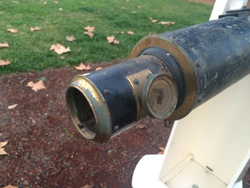
|
Fig York 02
Mount on Peir
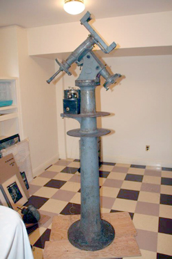
|
Fig York 03
Filters for filar illumination
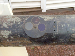
|
Fig York 04
T. Cook & Sons 1871
|
Fig York 05
Clockwork for RA drive
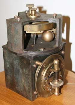
|
Fig York 06
Telescope tube
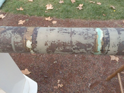
|
Fig York 07
Objective marked:
Mounted by
GRU68-Parsons
C.T.S. ?????
71 1/4" Focus
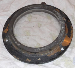
|
Fig York 08
Telescope tube
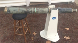
|
Fig York 09
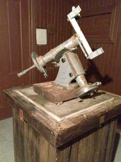
|
Fig York 10
Lower light is from EP hole.
Upper light is from 45 deg mirror.
|
Fig York 20 T. Cook & Sons 1871 mount
|
Fig York 21 T. Cook & Sons 1871

|
Fig York 22 pier for T. Cook & Sons
1871 mount
|
Fig York 23 telescope tube
|
Fig York 24 light from EP hole coming out
filter
|
Fig York 25 degree wheel hours in roman
minutes in numerals.
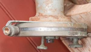
|
Fig York 26 "T. Cook & Sons 1871" mount
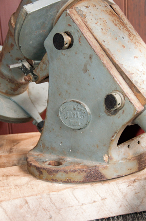
|
|
|
|
Porter Garden Telescope
I'm putting this here because I'd like to see one of these at
the Ukiah Observatory Park.
The first one made by Garden Telescopes
was the reflector version, but as of 2015 they are starting work
on a version that can be configured as either a reflector or
refactor. As of 2020 I don't see any mention of the
refactor version. This is made from machined metal
castings and is a work of art. Russel Porter made the
first on around 1920
YouTube:
Telescopes
of Vermont: Porter Garden Telescope
Reborn - Telescopes of Vermont has three other
videos about the PGT
1468973 Reflecting telescope, Porter
Russell W, Sep 25, 1923, 359/364 - Reflector (mirror)
1651412 Telescope, Porter
Russell W, Dec 6, 1927, 359/429,
248/181.1 - Refactor
(Lens)
Time Line
1610
Gailleo (Wiki)
discovers the moons of Jupiter (Wiki) The idea
that another planet can have moons violated Aristotle's cosmology
(Wiki).
By measuring the Occultation (Wiki) of
Jupiter's moon Io at different times of the year (different
distances between the Earth and Jupiter) the speed of light (Wiki)
can be calculated.
1630
William Gascoigne (Wiki)
sees a spider web inside a telescope where it's focused. He
invented the telescopic sight. He also developed the filar
eyepiece where a hair moved by a screw allows measuring the
diameter of the image, or refining the angle the telescope was
pointing. Note this filar eyepiece is different from the
later and improved filar micrometer (Wiki).
PS In an earlier version of this web page I used the term filar
eyepiece when I meant filar micrometer, now fixed.
1666
Isaac Newton (Wiki)
writes THE book on modern Optics (Wiki: History,
Optics) (my web
page on optics) and believes in a
corpuscular theory (Wiki),
i.e. light is made up of particles.
1725
James Bradley (Wiki)
tried to measure the distance to a star using stellar parallax (Wiki).
Note: At this time there was still debate about whether or not the
Sun rotated about the Earth. Heliocentrism
(Wiki)
was still being questioned and stellar parallax was part of that
debate.
But the dividing engine had not been invented and he could not
make the measurement. But in the process he discovered the
aberration of light (Wiki,
Wiki).
To make the parallax measurement you need to observe a star at two
times six months apart (with the Earth on opposite sides of the
Sun) to get the longest baseline. The exact two days of the
year depend on the location of the star.
The annual stellar aberration (Wiki)
is given by:
k = Θ - Φ ~ v/c
k is the constant of aberration (20″.49552)
Θ is the arrival angle of the light
Φ is the declination of the telescope
v is the speed of the Earth in it's orbit around the Sun (29,780 m/s)
c is the speed of light (299,792,458
meters/second)
1775
Jesse Ramsden (Wiki)
invents the geared screw cutting lathe (Wiki)
in order to make a precision screw to match a worm gear for a dividing engine. The 45"
diameter engine has one tooth per minute of angle and a dial on
the worm screw (Wiki)
probably could be read to 10 seconds of angle.
By the end of the 18th century angles could be measured using
Vernier scales on engine divided circles to 10 seconds of
arc. Star positions could be further refined by using a
filar micrometer to better than one arc second. Today we can
measure fractions of a milli arc second (0."0001).
1838
Friedrich Bessel (Wiki)
measures the parallax of 61 Cygni (Wiki: RA 21h 06m 53.9434s,
Dec +38° 44′ 57.898″
Note the declination) using a Heliometer (Wiki) which
was designed to measure the diameter of the Sun, but also can make
precise measurements of angles. Wiki says the Heliometer was
better than a filar micrometer (Wiki)
in handling atmospheric turbulence (Wiki),
I don't understand why. Note the the "seeing" gets worse as
the size of the telescope objective gets larger, so for telescopes
under 6 inches seeing is not much of a factor, but for scopes over
one foot diameter it's a real factor, so for Astrometry (Wiki) you
don't want large diameter telescopes. Hence the 4" objective
diameter of the Latitude Observatory telescopes.
1845
James Clark Maxwell (Wiki)
publishes his equations (Wiki)
that describe electromagnetic radiation and treat light as a
wave. The speed of light can be calculated from the
permittivity (Wiki) and
Permeability (Wiki)
of the medium the light is traveling through. Since both
these numbers were known for a vacuum the speed of light was
calculated and checked against the then known value and it
matched.
But there was a debate about the nature of light, was it a
particle or a wave and there were experiments that gave both
answers.
1887
The Michelson–Morley experiment (Wiki)
is published. They were trying to measure the speed of light
in the aether (Wiki)
but failed. They published their negative result (this takes
a lot of guts to stand up and say you were wrong, even
today).
1889
Getting the constant of aberration to better than an arc
second was critical. Also note the use of observatories at
35o 16' north and south to measure zenith
distances. Note this is tied up with measuring the speed of
light. It was not yet clear if light was a wave or
particle. [Ref 3]
1890
Dr. Kiistner reports a
problem in that the latitude of his observatory is changing. [Ref 2]
1905
Albert Einstein publishes the Special Theory of
Relativity (Wiki: History,
TOR)
References
1. Optics by Eugene Hect
& Alfred Zajac, 1974, ISBN: 0-201-02835-2 - used for the Time Line
2. Progress of Astronomy
by William C. Winlock, Annual
Report of the Board of Regents of the Smithsonian Institution,
July 1890
3. Annual
Report of the Board of Regents of the Smithsonian Institution,
July 1889
Michelson's Recent Researches on Light
by Joseph Lovering pg 449 (Wiki)
- Talks about various ways the speed of light had been
measured. Michelson's early experiments used a revolving
mirror, but had a flaw. The final experiment was done
using a interferometer (Wiki).
"As late as 1872, Le Verrier thought that a new measurement of
tbe velocity of light by Fizeau very important in tbe
interest of astronomy; and in 1871, Cornu wrote that tbe
parallllx of the sun, and hence the size of the earth's orbit,
were not yet known with the desirable precision. In 1875,
Villarceau made a communication to the Paris Academy on the
theory of aberration. He says that the parallax of tbe sun by
astronomical measurement is 8".86. Foucault's velocity of light
combined with Struve's aberration makes the sun's parallax
8".86. Cornu's velocity of light gives the same result only when
it is combined with Bradley's aberration, which differs from
that of Struve by 0".20. Villarceau thinks that there is an
uncertainty about the value of aberration on account of the
motion of the solar system. 'In 1883, M. O. Struve discussed
seven series of observations made by his father, Nyren, and
others, with various instruments and by different methods, at
the Observatory of Pulkowa. He was certain that the mean result
for the value of aberration was 20".492, with a probable error
of less than 1/100 of a second. This aberration, combined with
the velocity of light as deduced from the experiments of Cornu
aud Michelson, made the parallax of the sun 8".784; differing
from the most exact results of the geometric method by only a
few hundredths of a second. Villarceau proposed to get the solar
motion by aberration; selecting two places on the earth in
latitude 35o 16' north and south, and after the
example of Struve, observing the zenith distances of stars near
the zenith. The tangents of these latitudes are ± 1/SQRT(2) so
tbat they contain the best stations for obtaining the constant
of aberration, and the three components of the motion of
translation of the solar system."
The article on pg 749 Geographical Latitude by Walter B. Scaife
is about the non ideal characteristics of the Earth, not about a
problem measuring precise values.
PS. There's an article about a tower by a guy named G.
Eiffel and another by W.A. Eddy. 984 feet (300 meters)
tall compared to the Washington monument at 555 feet.
4. Annual
Report of the Board of Regents of the Smithsonian Institution,
July 1894 - contains a number of inetesting articles
On the Magnitude of the Solar System
by William Harkness pg 93- luminiferous ether is mentioned as
are the parallax of the Sun & Moon. Says 1639 was the
introduction of the micrometer eyepiece. Angle
measurements to better than 0".1 are needed for the parallax
measurements.
Variation of Latitude by J.K. Rees, pg 271 -
"This was the state of the investigation when Dr. Kiistner, of
the Berlin Observatory, published the results of his
observations made in 1884-85. Dr. Kiistner undertook some
observations for the trial of a new method for the determination
of the constant of aberration. On reducing his observations he
obtained resnlts which were not at all satisfactory. A careful
examination of his work led him to make the announcement that
the unsatisfactory valne for the aberration constant was due to
a comparatively rapid, though very small, change in the latitude
of the Berlin Observatory-" that from Augnst to November, 1884,
the latitude of Berlin had been from 0.2" to 0.3" greater than
from March to May in 1884 and 1885."
"The lecturer threw on the screen illustrations of several forms
of zenith telescopes, and described the new form made by
Wanschaft; of Berlin."
5. Tau Beta
Pi - Wandering
Pole, Wobbling Grid, 2016 by Trudy E. Bell (Home page)
A history of the latitude observatories along with a
number of the people involved (and their portraits).
Ref 6.
Notes
on Polar Alignment Methods - Observatory Class Telescopes -
Ref 7.
Circles, Clocks, Ships, and Wires: Meridian Circles within
Innovative Assemblages in 19th-Century America, Trydy E. Bell, 1
June 2023, (ahierscfv-3950.pdf)
Links
Flickr - survey
marker photos -
National Parks Service -
Astronomy and Astrophysics - Gaithersburg
Latitude Observatory -
NOAA (National Oceanic and
Atmospheric Administration) -
Gaithersburg
International Lattitude Observatory - Wendy Woodland
Martin
Bradley - The person most responsible for saving the
observatory - photo
sequence of THE oak tree with star background - Telescope
used in Ukiah -
Paul K - Photos
taken during 30 May 2009 tour of buildings.
California's
First Observatories. By Peter Abrahams. Ukiah
observatory had determined it's latitude and published it in 1897.
Flamsteed
Astronomy Society -
NWAC - Precision
Regulator Clocks Gallery - Strasser
& Rohde
Popular Science Monthly - Nov 1909 "The
Shifting of the Earth's Axis" by Dr. Sidney Dean Townley
(Stanford univ) - mentions Euler's formula of 1765 giving a 306
day period if the Earth was rigid. The actual period is more
like 427 days. But the axis does not repeat period to
period. As a possible explanation:
"Ah see by de papers dat de urf's
axis am a wobbling an' dey dunno wat fo'. But ah know wat
makes de urf's axis wobble. Do you see all dis oil dese
men am a takin' out of de urf? Well wat do you spose de
good Lord put dat oil in dere fo'? Wy to grease de axis
wif, of course, an' when dey take it all out, wat else can de
axis do but to wobble." Attributed to a Preacher in the oil
region of Texas, but probably the Townley's humor.
39315 Altitude Instrument, March 29, 1881, S.C. Chandler,
Jr. - aka Chronodeik or Almucantar - a telescope coupled to a
pendulum so that it points straight up.
"The Observatory" of the Royal Astronomical Society, 1899 (Vol
XXII) - pg 445 - Book Review "A Treatise on Instruments" published
in German 1899 mentions the Chronodeik is in the book along with
typical data.
The SAO/NASA Astrophysics Data
System - The Astronomical Journal - No.
1180 page 219 " - report for year: 1 Jly 1948 - 30 Jun 1949
Systems for the Determination of Polar Motion, May 1977,
NOAA - Continuing the Lat Obs operations mainly as astronomical
& navigational reference frame also may link to/from
earthquakes. Plan to continue for 50 or 100 more
years. In 1898 the International Geodetic Association (IGS)
created the International Latitude Service (ILS) (the name changed
in 1962 to International Polar Motion service (IPMS)) of 6
stations all located at 39:08 North to observe 12 groups of 12
stars. Later the stations at Cincinnati dropped from the
service and Tchardjui was replaced by Kitab. Gaithersburg
was non operational from 1916 to 1932, but Misuzawa, Ukiah, and
Carloforte gave almost uninterrupted service. Also starting
in 1962 more observatories were added at various latitudes
bringing the total to about 50 observatories observing not only
stars but also the Moon, artificial satellites and quasars using
optical, laser and radio methods.
The observatory locations given in this paper differ from those
shown above probably due to the reference frame used. The
paper was pre global navigation and GPS so used an older less
accurate country specific reference frames.
The National Museum of American History - Wanschaff
Zenith Telescope
Theory of the Motions of Rigid Bodies 1765 Euler (Wiki:
Euler angles)
Yahoo Group: Antique
Telescope Society - web page: Antique Telescope Society
Stellar
aberration due to the orbit of the earth (around the sun)
= 20.5 arc seconds, around the Earth = 0.32 arc seconds.
Frank
Schlesinger testing of automatic Zenith Camera at Allegheny
Observatory
Special thanks to the Mendocino County Historical Society and the
Held Pouge Librar
Back to Brooke's PRC68,
Astronomy, Binocular, CCD Astronomy, Star Magnitude, Personal Home
page
page created 31 July 2007