8" Mini Shear Break
© Brooke Clarke 2006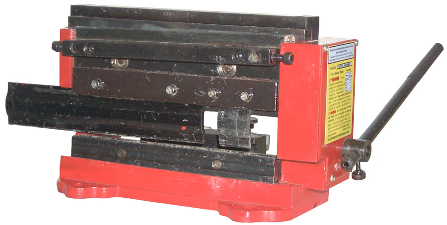
Description
Shear
Missing Accessory
Guide
Shear Blades
Break
Upper Dies
Lower Die
Applications
Hints
What goes Wrong
Suggested Improvements
Sample Sheet Metal Packs
Phosphorous Bronze
Tin Snips
Brooke's other Metal Working web pages
Links
Description
This is a combined 8" sheet
metal shear
and an 8" bending break. It's sold by Harbor Freight as
their SKU
number 90757
and by Northern
Tool
+ Equipment as Item
#
143361. The Harbor Freight version is painted red
and the
Northern Tool version is painted blue, but otherwise they seem
to be
the same. The Micro-Mark 83213
is painted White and includes the cutoff guide (Missing
Accessory on
the other two versions). The Micro-Mark Manual
has some different information from the Harbor Freight manual.
This may also be called a pan and box break because it can bend metal that already has prior bends. Also called a press break, which is different than the folding type of break. The Harbor Freight 18" break 39103 is similar to a flat table top with a hinge. To use it you need to trap the metal using the supplied bar with C clamps then pull up on the handles. But this type of break can not make a box where there has already been a prior bend.
This is made by Sieg, the same company that makes the Mini Machine Tools.
There is a Profiform version that comes in two widths called the 200 (8") or 320 (12"). It's manual goes into some detail about setting the cutting tools. When properly set you can cut typing paper. This version has many accessories available that would also work on the Harbor Freight version.
The 12" Bench Top Hand Shear does the job I was trying to do with this product, i.e. cut Printed Circuit Boards. Plus it can cut other things, like paper to make business cards.
Shear
The shear is at the top and
consists of
a horizontal top cutting bar and a sloped lower cutting
bar.
There is a gap in the top of the casting that's less than 2
mm
0.079" deep that limits the thickness of material that you can
cut (1.5
mm spec = 0.059"). 1/16" printed circuit board material
(0.0625)
just fits and is easily cut. It would be better if the
casting
was sanded to knock off the high spots (mainly paint but also
casting
bumps). This was my application.
4 Jun 2007 - The shear will cut the ExpressPCB Mini boards (2.5" x 3.8") where typically the first cut is about 1.25" with no problem. But if you're cutting a board that has 3 or more inches under the blade then it's very difficult. I've found using a scribe to weaken the board on the top and bottom prior attempting to shear it helps. For really large boards I still use the scroll saw that bolted under a table in the garage.
27 Oct 2007 - The Harbor Freight 38413 Throatless Shear may be a better way to cut printed circuit boards? If you have one let me know.
A 3 foot floor mounted sheet metal shear that's foot operated will cut a 12" PCB like it was butter, but they are big and cost more than what I want to spend for this.
I think the problem is the design of the mechanism that drives the blade. There's not enough leverage and with more leverage the drive pins will snap. But I haven't done any calculations to see what the stresses are in the shear and frame. If they are low for say a 5" wide 1/16" double sided PCB then it would be worth looking at a better drive system, like a hydraulic ram.
Missing Accessory - Cutoff Length Guide
The Lower Blade Support Bar (Item 8) has a couple of 8 mm
holes in each
end and there are a couple of pinch bolts that are intended to
hold
something. As of 16 Feb. 2006 I think the missing
accessory is a
right angle cutting guide. When installed the guide
would allow
you to align material on the guide and then make a cut 90
degrees from
the guide. This would allow squaring up material that
started out
with only one straight side. But I have not seen anyone
offering
this useful accessory. As it is now if you cut out a
piece of
metal that's small enough to fit into this mini shear using
tin snips
or a power sheet metal cutter (Harbor Freight 92148
electric sheet metal shear) it will not be square. So
without the
missing guide you need to do layout and marking of the work
piece just to get it square. With the missing guide it
would be a
snap to square it up.Guide (Item # 16)
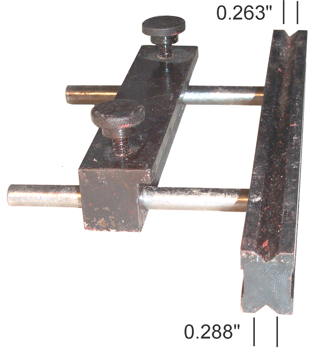 The
Guide
(16)
has a couple of thumb screws that pinch on the two 8
mm rods coming out of the lower "V" groove die. The
purpose of
the guide is to both set the length of metal to be bent and to
keep it
parallel to the bending line. The Guide has a lip that
must be
positioned on the top side and facing the bending dies.
It would
be wrong to feed the metal below the lip and above the rods
because
doing so would not allow the metal to move upwards as it's
bent.
So the tip of the lip must be the intended stop for the
metal.
But the amount of lip protrusion is only 4.83 mm
(0.190"). This
is about the length of the flat on top of the lower die, but
it is not
long enough to be over the bending line. If it was half
(0.311")
of the lower die width (15.71 mm or 0.622") then when
closed the
length of the material to be bent would be zero. If the
guide was
moved 0.25 inches away from the lower die the material that
was bent
would be 0.25" , etc. making setting the positon of the guide
easy.
BUT that's not the case. So was the guide made
improperly,
or is there some reason for the strange lip protrusion
distance?
The
Guide
(16)
has a couple of thumb screws that pinch on the two 8
mm rods coming out of the lower "V" groove die. The
purpose of
the guide is to both set the length of metal to be bent and to
keep it
parallel to the bending line. The Guide has a lip that
must be
positioned on the top side and facing the bending dies.
It would
be wrong to feed the metal below the lip and above the rods
because
doing so would not allow the metal to move upwards as it's
bent.
So the tip of the lip must be the intended stop for the
metal.
But the amount of lip protrusion is only 4.83 mm
(0.190"). This
is about the length of the flat on top of the lower die, but
it is not
long enough to be over the bending line. If it was half
(0.311")
of the lower die width (15.71 mm or 0.622") then when
closed the
length of the material to be bent would be zero. If the
guide was
moved 0.25 inches away from the lower die the material that
was bent
would be 0.25" , etc. making setting the positon of the guide
easy.
BUT that's not the case. So was the guide made
improperly,
or is there some reason for the strange lip protrusion
distance?Also, how to determine which "V" goove in the lower die should be used?
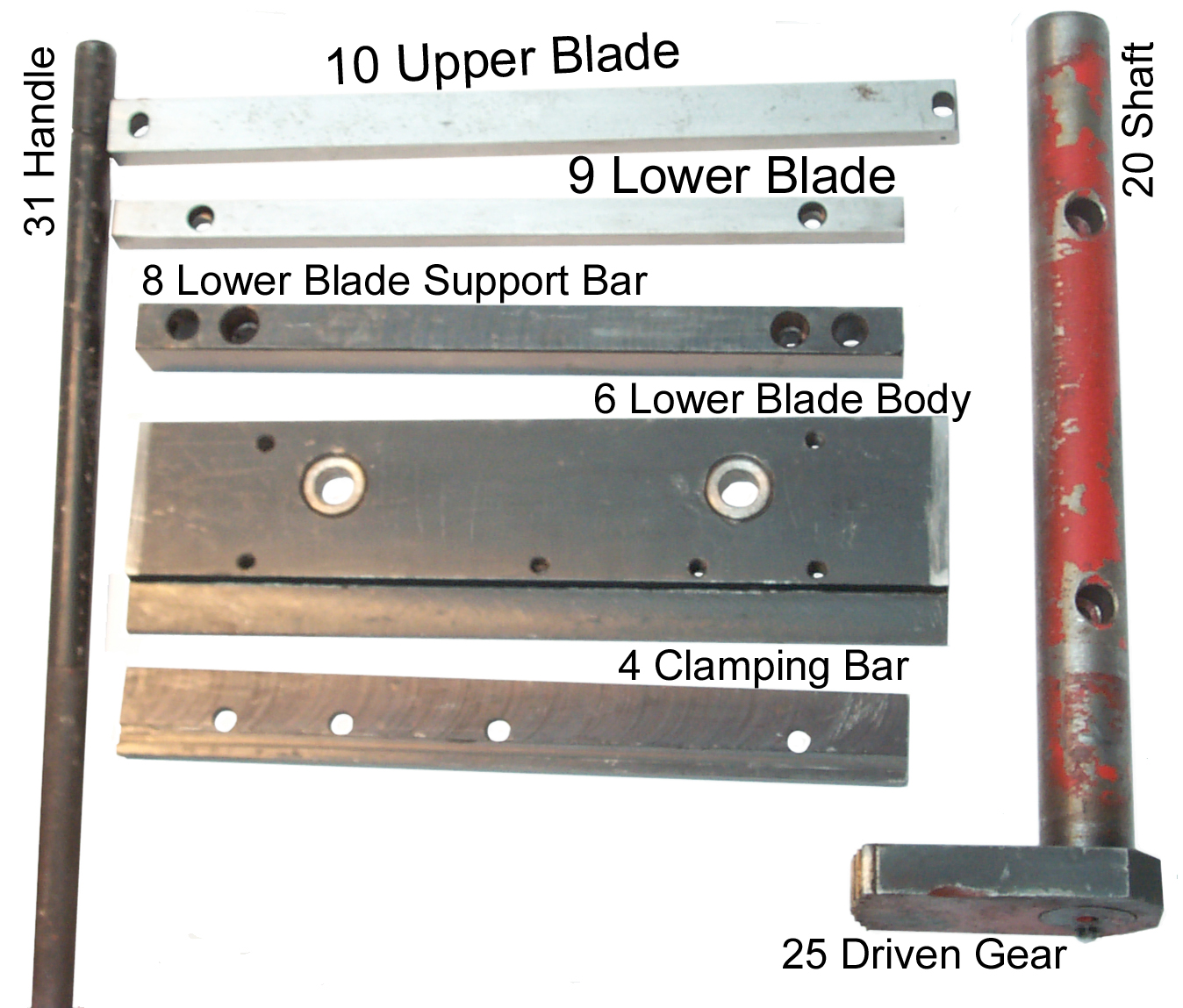
Shear Blades (9 & 10)
The blades are rectangular in
cross
section so that they can be installed 4 different ways, each
of which
presents a new cutting edge.
Break
The break is at the bottom of
the
tool. It is of the type that has a lower die shaped
like a "V"
block and an upper die that has a 90 degree "v" point.
When the
upper die is pressed down on sheet metal it's bent into a 90
degree
angle if the die is pressed home.
Upper Dies
The tool comes with an 8
inch wide top
die installed, but also supplied are four narrow dies of
different
lengths. This
allows setting up the break to bend a number of different
widths.
Lower Die
The lower die is a bar with
a "V"
groove on the top side and another "V" groove on the
bottom side.
The grooves are of different depths to accommodate
different material
thickness. Swaged into this die are a couple of 8 mm
rods that
extend back to a "Guide" that has a couple of thumb screws
for pinching
it to the rods. This allows setting the length and
squares of the
metal prior to bending.
Applications
- Cutting Printed Circuit Boards - I received an email
saying that
the 8MSB they received would not cut a 1/16" PCB out of
the box.
I'm guessing this particular unit got mis-aligned during
shipment
and/or has a number of surfaces that are painted instead
of smooth and
greased. TBD.
- Making Zero Gauss Chambers (mini boxes made from Mu-Metal)
- Prototype sheet metal work
- Learning what can easily be done and what's impossible
Hints
Bending Metal
In the above photo the top 8 inch die has been repositioned to the left and a couple of the small top dies have been installed on the right. The hope was to have just one setup, but for a mini box that's 1 x 1 x 3 3/4" it did not work. After some bends you need to remove the top dies to get the part out of the break.I'm making drawings and printing them at 1:1. Taping the drawing onto the metal and cutting the metal to the drawing.
Do not use scissors or shears to cut the notches. It will cause the metal to get bent (not flat). Do use a nibbler which does not bend the metal then with a vise and file clean up the edges. I tried using the 18 Gauge Electric Metal Shear 92148 but the thin metal was very distorted after cutting.
Klein makes a nibbler very similar to the one I have.
Maybe after a lot of practice my precision will improve, but for now some tolerance needs to be part of the design. Even better is to make one half of the box, measure it then make the other drawing to fit the existing part (selective assembly was the norm before tolerances were developed.)
8" Digital Calipers (Harbor Freight 47260) are very handy for design and layout of parts for this shear break.
Cutting PCBs
Each time you use the 8MSB for cutting anything, cycle the blade up and down to be sure that it moves freely and that the blades do not collide.The stock 8MSB has paint runs on the top surface of the frame casting and these will keep a 1/16" from being positioned in some spots and may keep it out all together. Sand paper will get rid of the high spots. Still working on a good way to do this without taking apart the top cutting blade.
What goes Wrong
Drive Pins
 29
April
2006
- Yesterday I received a replacement 8MSB and cycled the
cutting blade up and down with nothing in there and it worked
fine. Then tried to cut a 3 3/4" wide PCB, but it would
not fit,
so used sandpaper to knock off the paint runs. Then cut
the board
up with no problem (this done without bolting it down).
This
means that the first 8MSB was put out of alignment by my wife
using it
as an anvil. The hammering on the top blade clamp did
something
to the blade alignment.
29
April
2006
- Yesterday I received a replacement 8MSB and cycled the
cutting blade up and down with nothing in there and it worked
fine. Then tried to cut a 3 3/4" wide PCB, but it would
not fit,
so used sandpaper to knock off the paint runs. Then cut
the board
up with no problem (this done without bolting it down).
This
means that the first 8MSB was put out of alignment by my wife
using it
as an anvil. The hammering on the top blade clamp did
something
to the blade alignment.When I get the new drive pins for the old one I'll learn how to do the blade alignment. This also means that you should not use washers or other spacers to widen the gap since they may not be stable enough to maintain the blade alignment.
20 April 2006 - Tried to cut a panelized printed circuit board but it would not cut. I don't have the shear break bolted down and in the past was able to easily cut printed circuit boards that were narrower. So tried using more force, but you can't use much when the shear is not bolted down. Then without hearing or feeling anything unusual the lower blade stopped moving. After taking it apart is was clear that both drive pins had sheared. Harbor freight offered "used" parts, i.e. taken off another mini shear break that was not sellable, but I opted to get new pins which will take 6 to 8 weeks.
After more inspection the following problems are apparent:
- Many surfaces where metal parts are rubbing against other metal parts are painted on one or both surfaces. The paint needs to be removed and replaced by grease.
- Where metal parts rub against each other there are burs that need to be filed down.
- The Drive pins (Item # 19) are a poor design. The
tapped
hole extends to the narrow neck area making the neck very
weak. A
0.1365 inch diameter hole through a metal part that's only
0.280 O.D.
leaves only a 0.071 inch thick wall for an area of
0.047 square
inches. If the tapped hole was a little less deep
the area at the
neck would be 0.062 square inches or 130 percent
more. In
addition to the difference in area, the hole also acts as
a stress
riser
further weakening the part. The tip of the drive pin
should be a
sphere, but these look more like a couple of chamfers were
used to
approximate a sphere. There are shiny metal spots on
the edges of
the flat part.
A new mini shear break has arrived and is not being taken apart.
Harbor Freight will take orders for spars parts, but it takes many many months to get them (so for nothing has arrived). Micro Mark stocks cutting blades but will not order any other spare parts.
Shear
On a few occasions I've been able to make a nice cut, but the next time not. You would think it would work on the 10 mil Phosphor Bronze (see below or brass).Maybe there needs to be another adjustment or fix. So examining the parts:
 |
The
Lower Blade (9) sits on top of the Lower Blade Body
(6) and they both
ride in an open channel on the front of the
base. Any slop
between the moving parts and the base will result in a
repositioning of
the lower blade. Lathes have gibs to adjust this slop but here there are none. Maybe offsetting each end of the blade relative to the lower blade body is the adjustment method? |
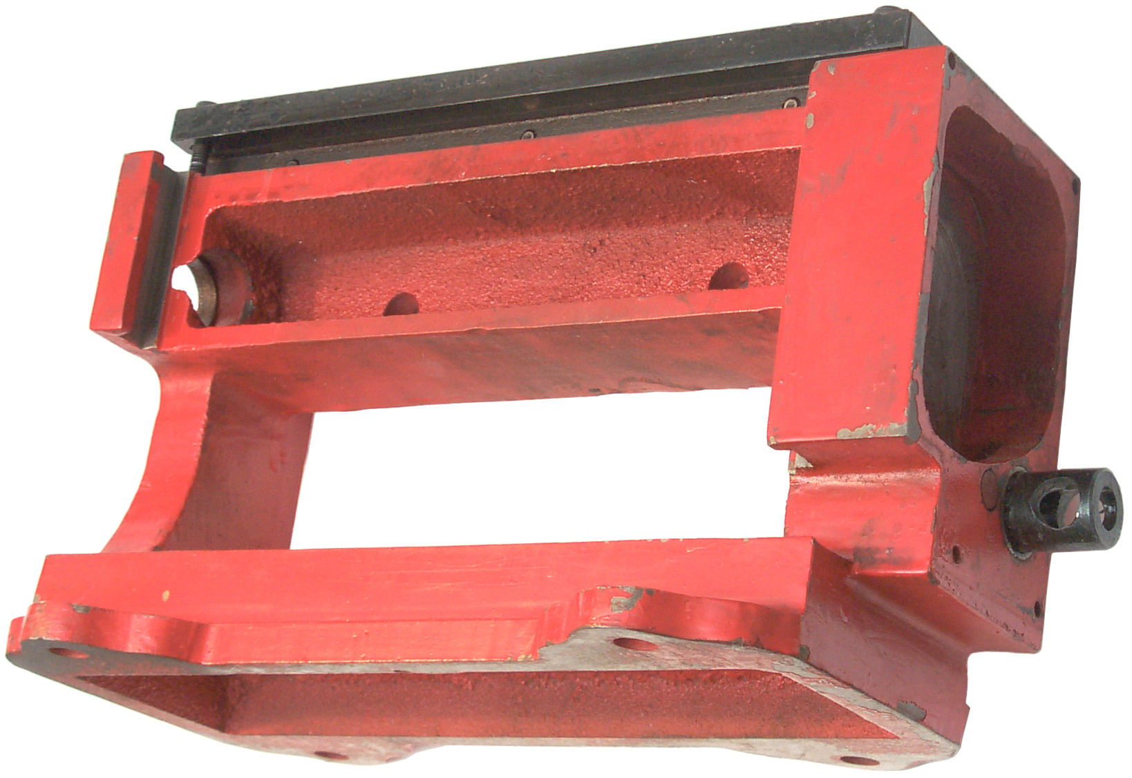 |
The base (1) has the
Upper Blade
Holder (14) and the gear box parts: 30 Driving gear 27 Gear Shaft (with hole for Handle (31) in front of the gear shaft you can see the end of 22 transfer gear shaft and the 23 transfer gear is out of sight. The two gears have the same number of teeth and serve to change the direction of rotation. The far end of the main shaft (20) rides directly on the casting in the open hole at the left of this photo. In a similar manner the near end rides on the casting. The left open channel for the lower blade body (6) and lower blade (9) can be seen at the left of the photo at the front. |
Suggested Improvements
These are pending more work on
the old
unit. Coming about June 2006.
- removing paint that's between metal to metal moving surfaces and replacing it with grease.
- polishing the drive pin ends into shiny spheres and greasing them.
- Confirming that the slide assembly moves smoothly up and down without binding and greasing it.
- Remove the top cutting blade and it's support bar and removing all the paint on the top. This is the bottom of the slot where the printed circuit board needs to fit and if the paint is too thick or has a run a 1/16" PCB will not fit. So this is mainly to be sure the board fits cleanly.
- Clean off the old waxy grease from the drive gear teeth
and
replace with fresh grease.
-
I expect that the new replacement parts will also have the
tapped
hole
too deep.
Sample Sheet Metal Packs
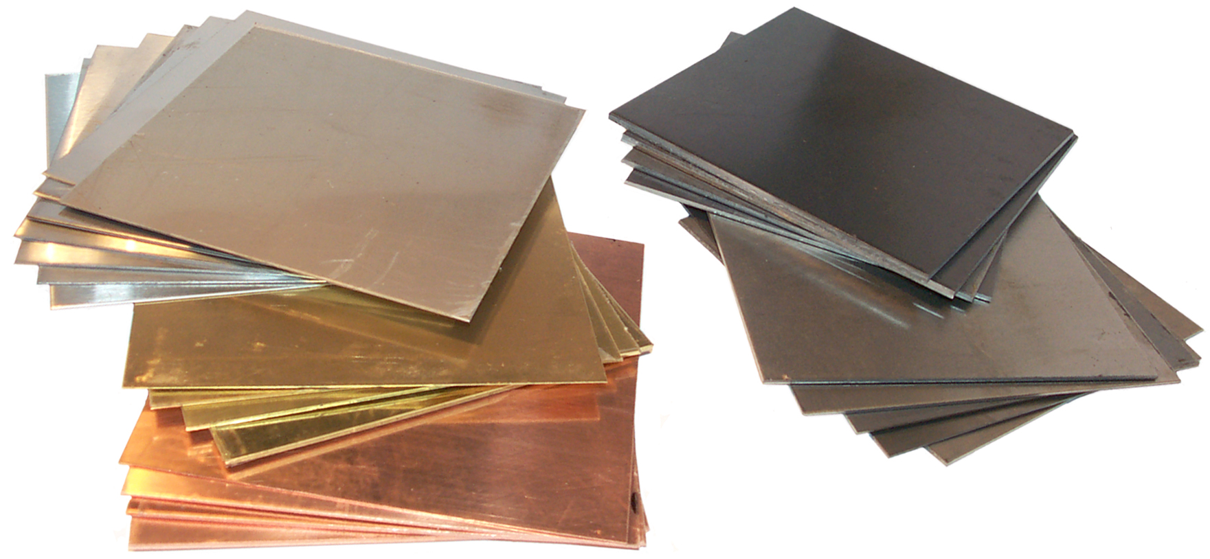
On Line Metals - offers a number of "Metal" packages offered under the catagory sample packages but these packages only have rod stock in various metals. But they also have sheet metal sample packs offered under each metal.
These sheet metal sample packs contain 4" x 4" samples in various thicknesses. Many of them are too thick to cut with the 8" MSB but many will work just fine.
Not shown is a sheet of Nickel Silver also from OLM.
On the left are the T-304 #4 and T-304 #2B Stainless Steel, Brass and Copper packs and on the top right the A569 Hot rolled steel and at bottom right the 4130 cold rolled steel.
Phosphorous Bronze
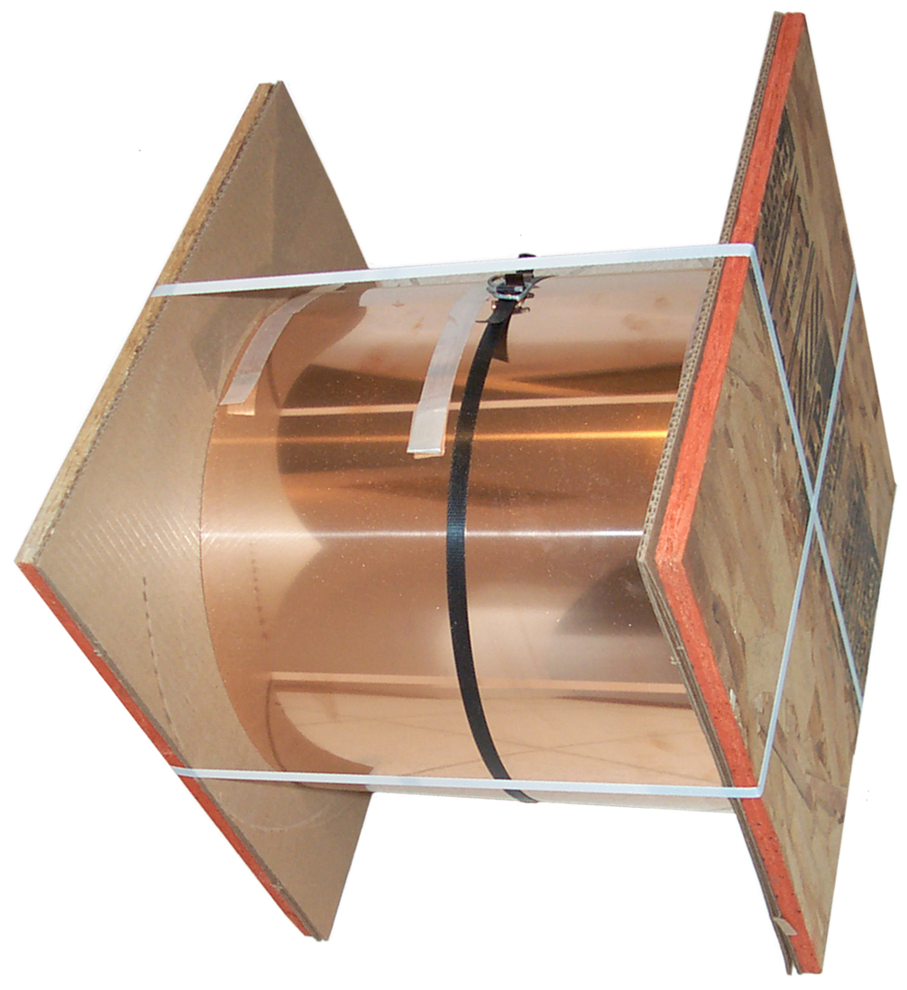
For making motor brushes for the Weeden Toy DC motor and the Small DC motor (similar to the Gilbert Toy Motor) I've got a roll of 12" phosphor bronze that's spring tempered.
A 6" strip can be cut off the roll with heavy scissors then sliced using the 8" MSB. But first the top cutting blade needed to be adjusted. The first try just folded the 0.010" thick metal. It also would not cut a 3x5" paper card.
Loosen the top front clamping hex screws and finger tighten them. Raise the lower cutting blade so it's past the top blade cutting edge. Loosen the adjusting lock nuts and run the hex adjusting screws forward with a small torque and lock the nuts. It should cut 3x5" card stock at any location across the blade. Adjust as necessary to get good paper cutting.
Now it does a good job on 6" wide metal.
To order a 3" x 3" x 0.009" piece of phosphor bronze see the Phosphor Bronze Brush Kit.
Tin Snips

These are the Enco 891-5590 Straight. Cut 12.5" Wiss Tin Snips
I have had other kinds in flavors like left cutting, right cutting or straight cutting that had serrated teeth on the blades. Also the Cutco heavy duty kitchen shears can cut a penny, but they too have serrated cutting blades that leave a rough edge on the cut metal. These shears were chosen to cut the phosphor bronze and brass sheet metal and most if not all these cuts are straight.
25 Sep 2008 - these will easily cut 1/16" PCB material for about half an inch per squeeze. So to separate a 2.5" x 3.8" ExpressPCB Mini board into three boards each 2.5" long (i.e. the cuts are 2.5" long) takes a couple of squeezes from each side. replaced by the 12" shear for PCB cutting.
Brooke's other Metal Working web pages
12"
Bench Top Hand Shear
5C Tool room lathes when working in the Microwave business the shop was full of them
8" Mini Shear Break
Active Storage - shelving and box sizes
Air Tools
Digital-Retro-Turbo-Encabulator
Drill Press used with 5C collets
Electric mains power Generators
Farm Hi Lift Jack
Geodesic Dome Connector Plates
Hints & Tips What Goes Wrong
Lathes for < 1" OD parts (5C collets)
Mini Machine Tools (Lathes and Mills) One of my dreams
Fasteners A page made for my own use with dimensions of common fasteners used for product design and for looking at new ideas for products
Measuring Tools Used mainly for reverse engineering
Pocket Tools
Links
Brooke's web pages
Mini Machine Tools - small lathes and milling machinesLathe - 5C collet size lathes for 1" and smaller parts
Length & Weight Measurements - tools
Fasteners
Mini Cut-off Saw
Pocket Tools - multi purpose tools
Electro Optical Gadgets - includes linear and rotation digital readouts
Micro Mark - 7x12 Lathe - also made by SIEG but much enhanced
LittleMachineShop -
[an error occurred while processing this directive] page created 16 Feb 2006.