| Size # - TPI |
Pitch 1/TPI inch |
Depth
of sharp thread COS(30 deg) /TPI |
Pitch dia |
Major dia (rod) |
Tap Drill |
Free
Fit Clearance Drill |
Pan Head |
Hex head socket Nut |
Sckt hd Cap Scrw |
Flat Head
Mach-Screw
82º |
Allen set Screw |
||||||
| max dia (-) & (+) |
Phil (+) bit # |
(-) Slot max |
max dia |
Allen Key Size |
dia |
H |
Driver |
||||||||||
| 0-80 |
0.0125 |
0.010825 |
0.0519 |
0.060 |
3/64 |
0.0469 |
#50 |
0.070 |
0.116 |
0 |
0.023 |
na |
0.096 |
0.050 |
0.119 |
0.026 |
|
| 1-72 | 0.013889 | 0.012028 | 0.0640 | 0.073 | #53 | 0.0595 | #46 | 0.081 | na | 0.118 | 1/16 | 0.146 | 0.031 | ||||
| 1-64 |
0.015625 |
0.013532 |
0.0629 | 0.073 |
#53 |
0.0595 |
#46 |
0.081 |
|
na |
0.118 |
1/16 |
0.146 |
0.031 |
|||
| 2-56 |
0.017857 |
0.015465 |
0.0744 |
0.086 |
#50 |
0.070 |
#41 |
0.096 |
0.167 |
1 |
0.031 |
3/16 |
0.140 |
5/64 |
0.172 |
0.037 |
|
| 2-64 |
0.015625 |
0.013532 |
0.0759 | 0.086 |
#50 |
0.070 |
#41 | 0.096 | 0.167 | 1 |
0.031 | 3/16 | 0.140 |
5/64 | 0.172 |
0.037 |
|
| 3-48 |
0.020833 |
0.018042 |
0.0855 |
0.099 |
#47 |
0.0785 |
#35 |
0.110 |
0.193 |
1 |
0.035 |
3/16 | 0.161 |
5/64 | 0.199 |
0.043 |
|
| 3-56 |
0.017857 |
0.015465 |
0.0874 | 0.099 |
#45 |
0.082 |
#35 | 0.110 | 0.193 | 1 |
0.035 | 1/8 | 0.161 | 5/64 | 0.199 |
0.043 |
|
| 4-36 |
0.27778 |
0.021651 | 0.0958 |
0.099 | #44 |
0.086 |
#30 |
0.1285 |
0.219 |
1 |
0.039 |
1/4 |
0.183 |
3/32 |
0.225 |
0.049 |
|
| 4-40 |
0.025 |
0.021651 |
0.0958 | 0.112 |
#43 |
0.089 |
#30 | 0.1285 | 0.219 | 1 |
0.039 | 1/4 | 0.183 | 3/32 | 0.225 |
0.049 |
0.05 |
| 4-48 |
0.020833 |
0.018042 | 0.0985 | 0.112 |
#42 |
0.0935 |
#30 | 0.1285 | 0.219 | 1 |
0.039 | 1/4 | 0.183 | 3/32 | 0.225 |
0.049 |
|
| 5-40 |
0.025 |
0.021651 | 0.1088 |
0.125 |
#38 |
0.1015 |
#29 | 0.136 | 0.245 |
2 |
0.043 |
0.205 |
3/32 | ||||
| 5-44 |
0.022727 |
0.019682 |
0.1102 | 0.125 |
#37 |
0.104 |
#29 |
0.136 |
0.245 |
2 |
0.043 | 0.205 | 3/32 | ||||
| 6-32 |
0.03125 |
0.027063 |
0.1177 |
0.138 |
#36 |
0.1065 |
#25 | 0.1495 | 0.270 |
2 |
0.048 |
1/4 ? 5/16 brass |
0.226 |
7/64 |
0.279 |
0.060 |
1/16 |
| 6-40 |
0.025 |
0.021651 | 0.1218 | 0.138 |
#33 |
0.113 |
#25 |
0.1495 |
0.270 |
2 |
0.048 | 1/4 | 0.226 | 7/64 | 0.279 |
0.060 |
|
| 8-32 |
0.03125 |
0.027063 | 0.1437 |
0.164 |
#29 |
0.136 |
#16 |
0.177 |
0.322 |
2 |
0.054 |
1/4 | 0.270 |
7/64 | 0.332 |
0.072 |
5/64 |
| 8-36 |
0.27778 | 0.024056 |
0.1460 | 0.164 |
#29 |
0.136 |
#16 | 0.177 | 0.322 |
2 |
0.054 | 1/4 | 0.270 | 9/64 |
0.332 |
0.072 |
|
| 8-40 |
0.025 | 0.021651 | 0.1437 | 0.164 |
#28 |
0.1405 |
#16 | 0.177 | 0.322 |
2 |
0.054 | 1/4 | 0.270 | 9/64 | 0.332 |
0.072 |
|
| 10-24 |
0.041667 |
0.036084 |
0.1629 |
0.190 |
#25 |
0.1495 |
#7 |
0.201 |
0.373 |
2 |
0.060 | 5/16 |
0.312 |
5/32 |
0.385 |
0.083 |
3/32 |
| 10-32 |
0.03125 | 0.027063 | 0.1697 | 0.190 |
#21 |
0.159 |
#7 | 0.201 | 0.373 |
2 |
0.060 |
5/16 | 0.312 | 5/32 | 0.385 |
0.083 |
|
| 12-24 |
0.041667 | 0.036084 | 0.1889 |
0.216 |
#16 |
0.177 |
I |
0.228 |
0.425
|
3 |
0.067 | 5/16 | |||||
| 12-28 |
0.035714 |
0.030929 |
0.1928 | 0.216 |
#14 |
0.182 |
I | 0.228 | 0.425 | 3 |
0.067 | 5/16 | |||||
| 12-32 |
0.03125 | 0.027063 | 0.1889 | 0.216 |
#12 |
0.189 |
I | 0.228 | 0.425 | 3 |
0.067 | 5/16 | |||||
| 1/4-20 |
0.050 |
0.043301 |
0.2175 |
0.250 |
#7 |
0.201 |
H | 0.266 |
0.492 |
3 |
0.075 |
3/8 |
3/8 | 3/16 |
0.507 |
0.110 |
1/8 |
| 1/4-28 |
0.035714 | 0.030929 | 0.2268 | 0.250 |
#3 |
0.213 |
H | 0.266 | 0.492 | 3 |
0.075 | 3/8 | 3/8 | 3/16 | 0.507 |
0.110 |
|
| 1/4-32 |
0.03125 | 0.027063 | 0.2297 | 0.250 |
7/32 |
0.2188 |
H | 0.266 | 0.492 | 3 |
0.075 | 3/8 | 3/8 | 3/16 | 0.507 |
0.110 |
|
| Size dia x p |
Pitch 1/TPmm mm |
Deepth of sharp thread COS(30 deg) /TPmm |
Pitch dia |
Major dia rod |
Tap Drill |
Free Fit Clearance Drill |
Pan Head | Hex head socket Nut |
Sckt hd Cap Scrw |
Flat Head
Mach-Screw90º
|
||||
| max dia (-) & (+) |
Phil (+) bit # |
(-) Slot max |
dia | H | ||||||||||
| 2x.4 |
2.5 |
0.346
[0.014] |
2.0
[0.079] |
1.6 |
2.6 |
4.0 |
4.0 |
1.0 |
||||||
| 2x.25 |
4.0 |
0.217
[0.0085] |
2.0 [0.079] | 1.6 |
2.6 |
4.0 |
4.0 | 1.0 |
||||||
| 2.2x.45 |
2.2222... |
0.390
[0.015] |
2.2
[0.087] |
1.75 |
4.5 |
4.4 | 1.1 |
|||||||
| 2.2x.25 |
4.0 |
0.217 [0.0085] | 2.2 [0.087] | 1.75 |
4.5 |
4.4 | 1.1 |
|||||||
| 2.5x.45 |
2.2222... |
0.390 [0.015] | 2.5
[0.099] |
2.05 |
3.1 |
5.0 |
5.0 |
5.0 | 1.25 |
|||||
| 2.5x.35 |
2.857... |
0.303
[0.0119] |
2.5 [0.099] | 2.05 |
3.1 |
5.0 |
5.0 |
5.0 | 1.25 |
|||||
| 3x.5 |
2.0 |
0.422
[0.017] |
3.0
[0.118] |
2.5 |
3.6 |
6.0 |
5.5 |
6.0 | 1.5 |
|||||
| 3x.35 |
2.857... | 0.303 [0.0119] | 3.0 [0.118] | 2.5 |
3.6 |
6.0 |
5.5 |
6.0 | 1.5 |
|||||
| 3.5x.6 |
1.666... |
0.520
[0.020] |
3.5
[0.138] |
2.9 |
7.0 |
6.0 |
7.0 | 1.75 |
||||||
| 3.5x.35 |
2.857... | 0.303 [0.0119] | 3.5 [0.138] | 2.9 |
7.0 |
6.0 |
7.0 | 1.75 |
||||||
| 4x.7 |
1.429... |
0.606
[0.0239] |
4.0
[0.157] |
3.3 |
4.8 |
8.0 |
7.0 |
8.0 | 2.0 |
|||||
| 4x.5 |
2.0 |
0.422 [0.017] | 4.0 [0.157] | 3.3 |
4.8 |
8.0 |
7.0 |
8.0 | 2.0 |
|||||
| 4.5x.75 |
1.333... | 0.650
[0.0256] |
4.5
[0.177] |
3.7 |
9.0 |
9.0 | 2.25 |
|||||||
| 4.5x.5 |
2.0 |
0.422 [0.017] | 4.5 [0.177] | 3.7 |
9.0 |
9.0 | 2.25 |
|||||||
| 5x.8 |
1.250 |
0.693
[0.027] |
5.0
[0.197] |
4.2 |
5.8 |
10.0 |
8.0 |
10.0 | 2.5 |
|||||
| 5x.5 |
2.0 |
0.422 [0.017] | 5.0 [0.197] | 4.2 |
5.8 |
10.0 |
8.0 |
10.0 | 2.5 |
|||||
| 6x1 |
1 |
0.866
[0.034] |
6.0
[0.236] |
5.0 |
7.0 |
12.0 |
10.0 |
12.0 | 3.0 |
|||||
| 6x.75 |
1.333... | 0.650 [0.0256] | 6.0 [0.236] | 5.0 |
7.0 |
12.0 |
10.0 |
12.0 | 3.0 |
|||||
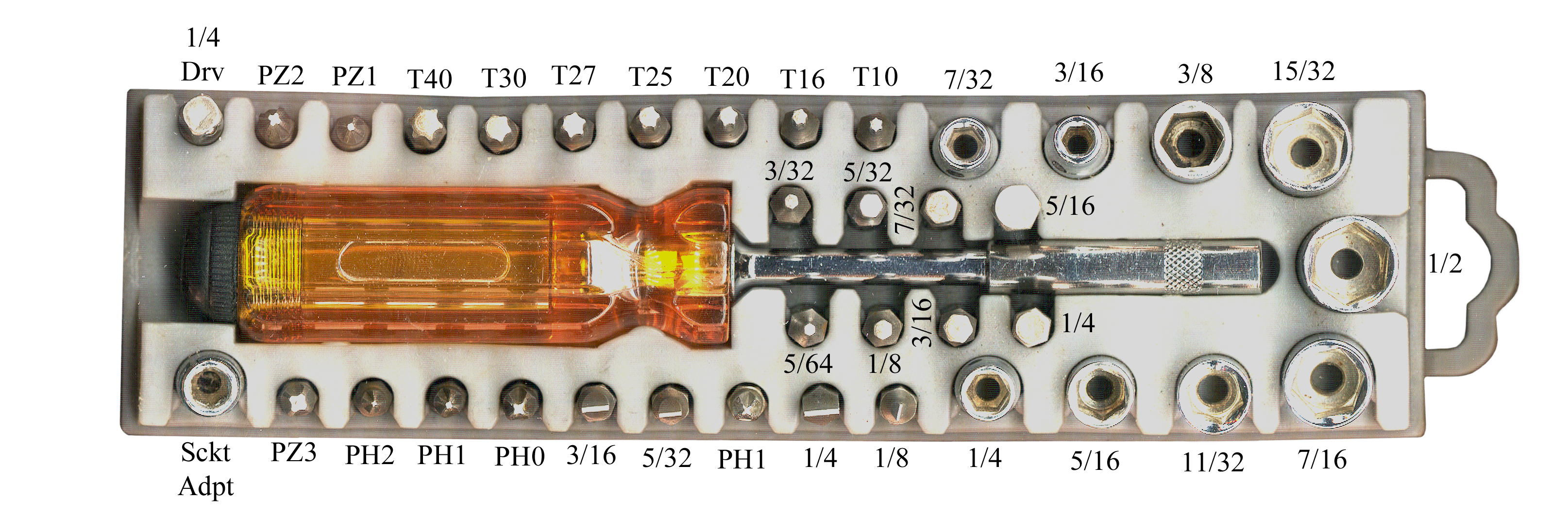
Fig 1 Tool roll wrapped around 4mm driver
set |
Fig 2 Spurgers & other tools on left,
4mm driver wet with lid off  |
Fig 3 4mm driver set. |
 |
AM ArrowMax makes three versions of their 4mm electric screwdriver. I thought I was buying the Pro set, but it turns out to be the mini set that does NOT have gyroscopic control. Note the gyroscopic model has a single button, whereas the other models have two buttons. |
Fig 1 Drill configuration screwdriver |
Fig 2 Straight screwdriver |
Fig 3 DeWalt 2-battery & Charger kit Added a couple of Wiha 75802 1/4" to 4mm hex adapters so that the AM Arrow bits can be used.  |
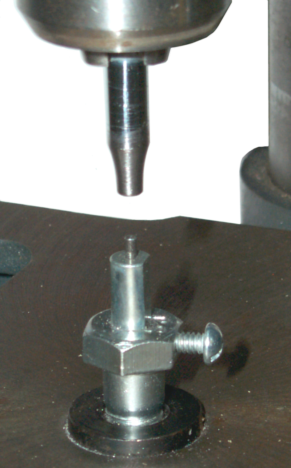 This is tooling
that allows using the press function of a Drill Press (not the drill motor) to
set eyelets.
This is tooling
that allows using the press function of a Drill Press (not the drill motor) to
set eyelets.

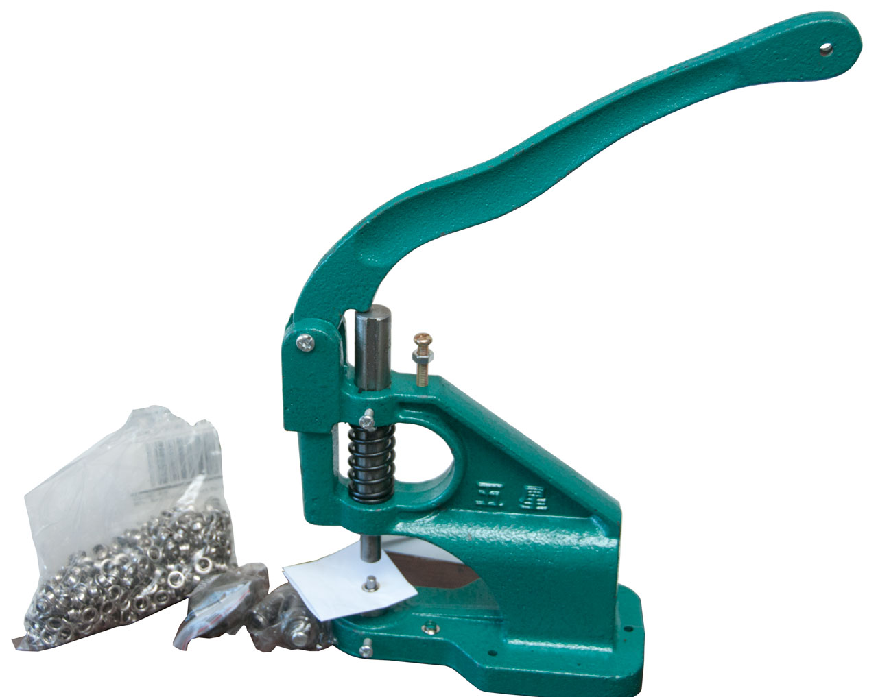
 The
next step up from hand tooling is an arbor press.
They come in 1/2, 1 and 2 ton capacities.
The
next step up from hand tooling is an arbor press.
They come in 1/2, 1 and 2 ton capacities. |
 |
 |
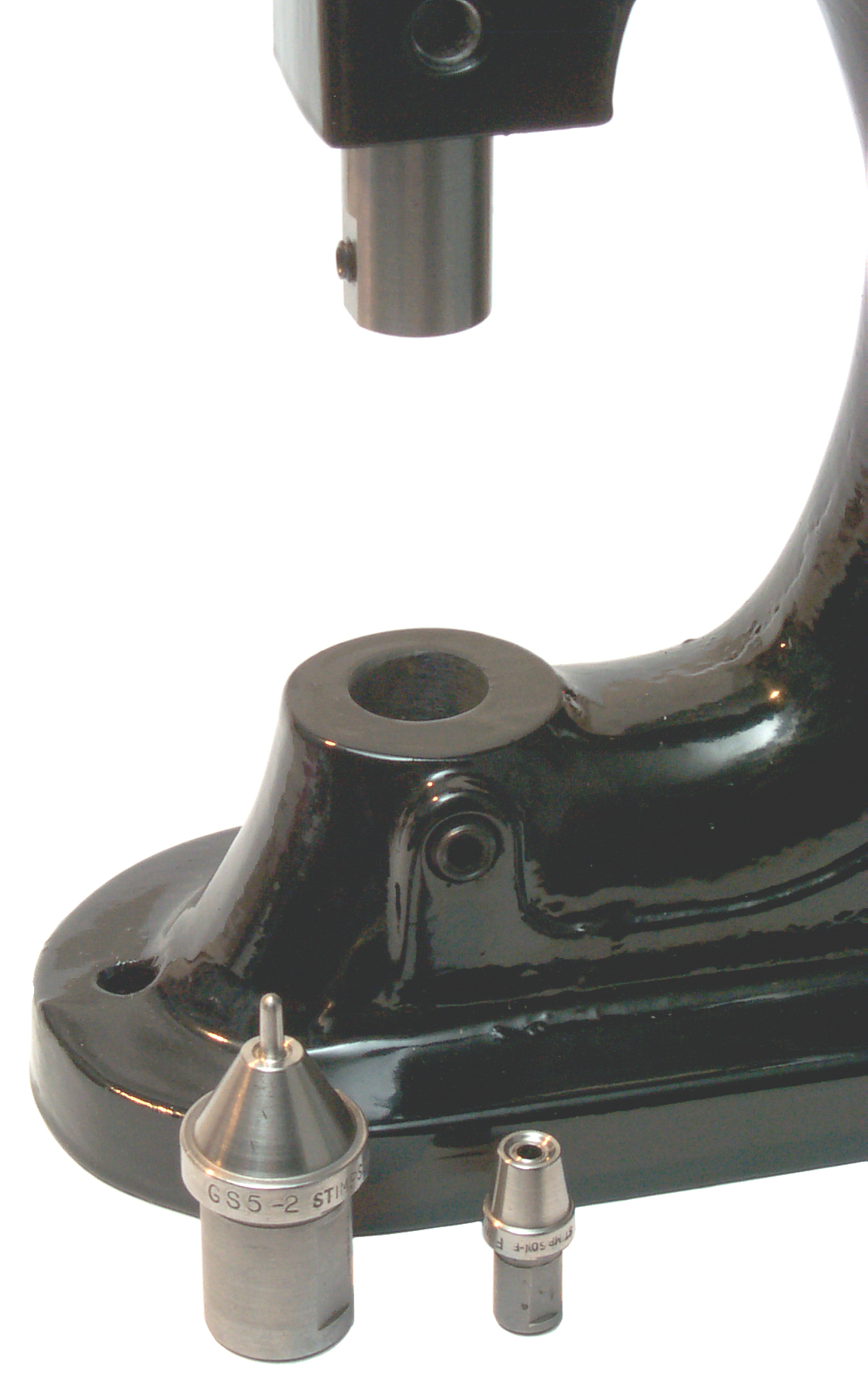
| Stimpson 405 Press |
GS-5 Stock tooling |
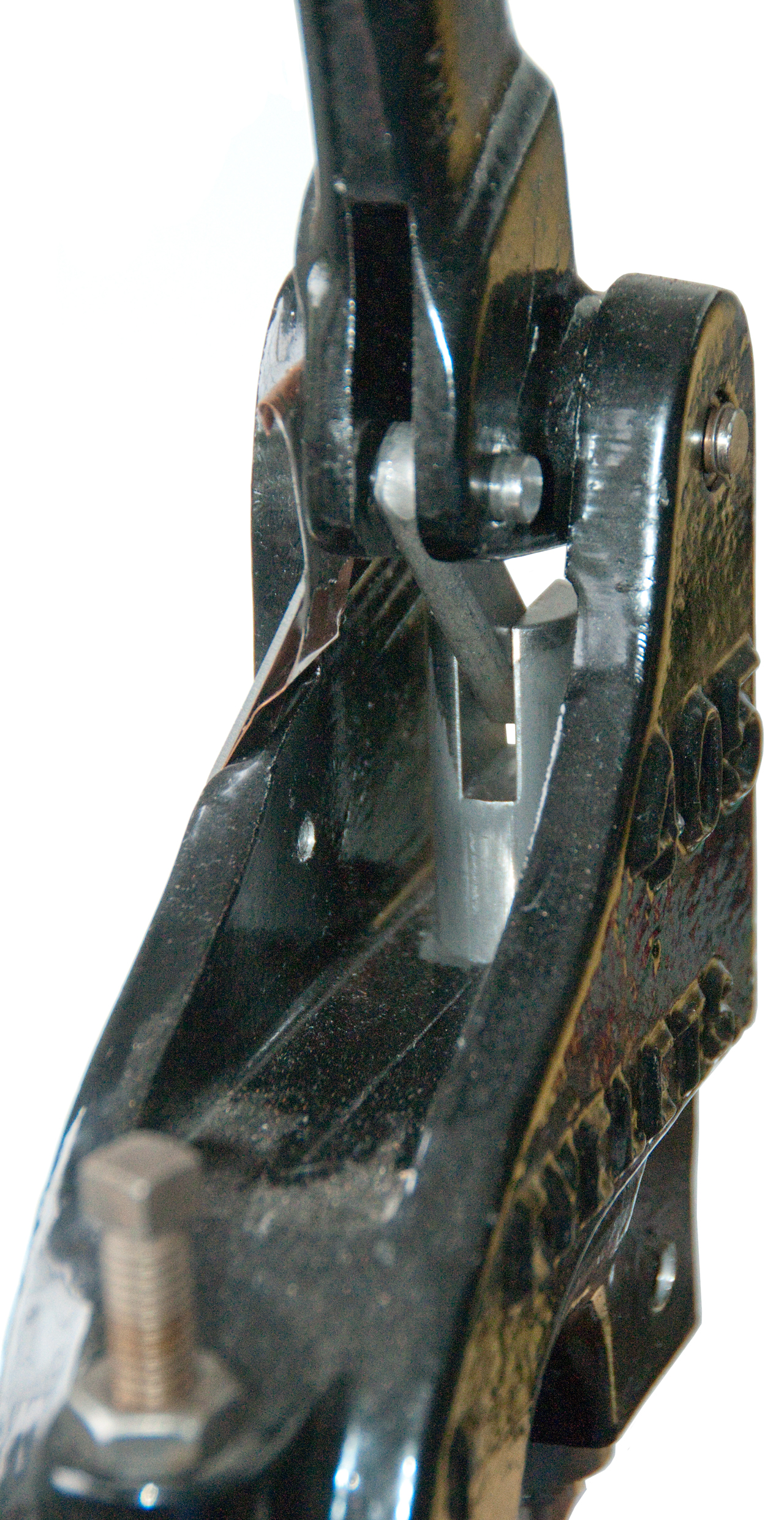
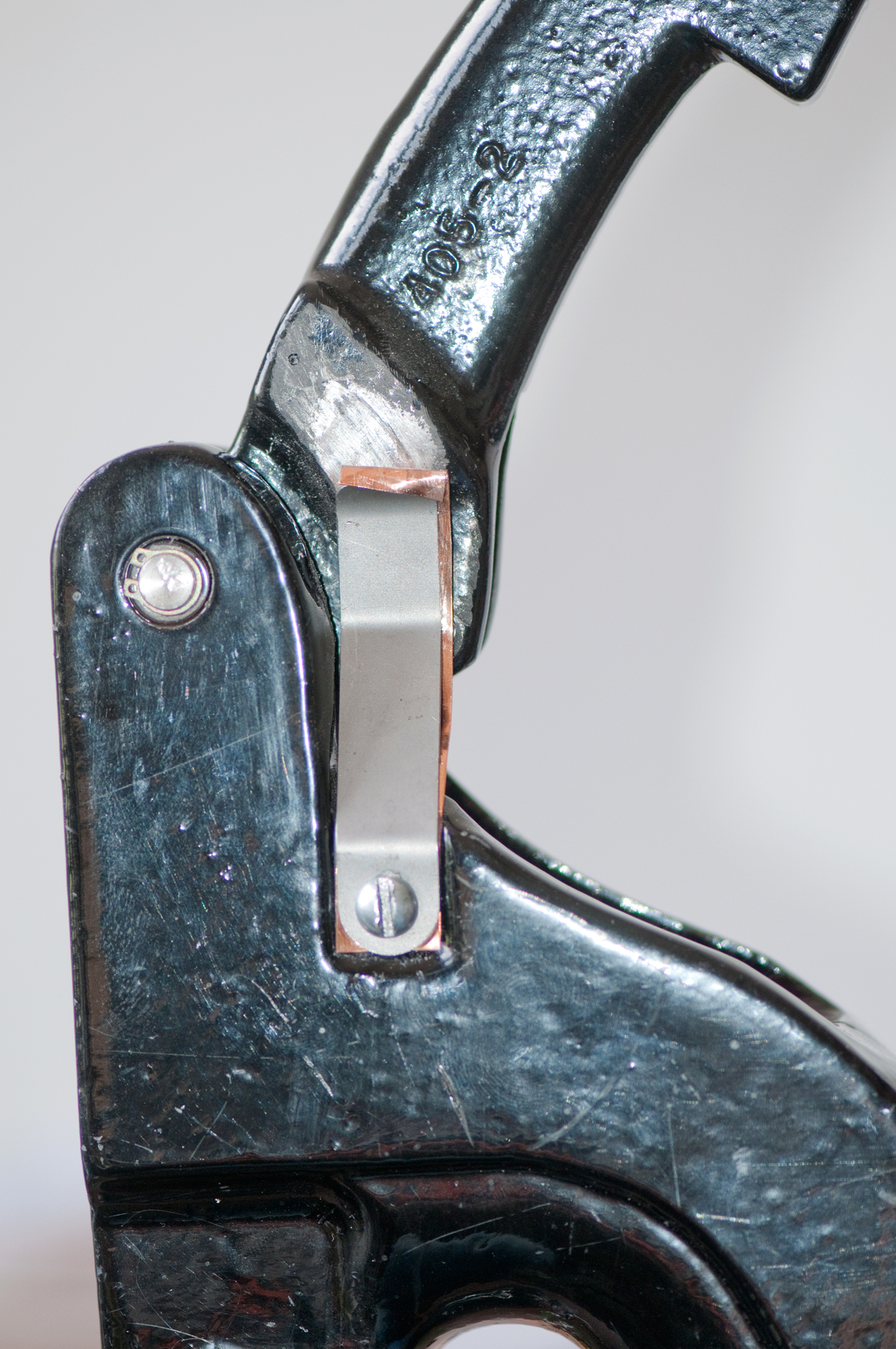
Compound linkage |
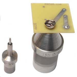 This is a custom tool made to install 9 Volt
battery snaps. The post in the center of the snap is spring
loaded and gets pressed down by the top tool which is shown to the
left upside down. The spring loaded post holds an eyelet,
the PCB and keeps the snap in place until the top tool sets the
eyelet. This is upside down from the stock tooling shown
above but is the correct way to manually do eyelets.
This is a custom tool made to install 9 Volt
battery snaps. The post in the center of the snap is spring
loaded and gets pressed down by the top tool which is shown to the
left upside down. The spring loaded post holds an eyelet,
the PCB and keeps the snap in place until the top tool sets the
eyelet. This is upside down from the stock tooling shown
above but is the correct way to manually do eyelets.There is a finger shaped metal strap that presses against the
hand lever so that when the lever is up it will stay
there. The problem is the metal of the strap (steel) is
very similar to the metal of the hand lever (cast iron) and so
there is galling. Along with the galling, and the main
reason for the "fix" is the very loud noise that's much worse
than fingernails on a blackboard.
372826 Eyelet-setting
machine, Edwin
B. Stimpson, Nov 8, 1887, 227/60;
221/167; 221/241 - auto eyelet feed, bench top machine
391208
Machine for Setting Eyelets, Edwin
B. Stimpson, Oct 16, 1888, - auto
eyelet feed, bench top machine
736163
Eyeleting-machine, Edwin
B. Stimpson, 1903-08-1, 221/182; 221/188 - foot operated from standing
position, free standing machine
863330
Headless rivet, Edwin
B. Stimpson,1907-08-13, 411/457; 256/54 -
A normal rivet is a solid part, but the tubular rivet has a hole in the end that's going to be formed so that end looks very much like an eyelet. It's a lot easier to form the tube than the rod.
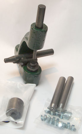 |
These are some rivets and rivet tools from Mike's "A" Ford-able Parts. I get the feeling the Model A was held together by rivets (not sure of the factory used tubular or solid ones. The tool holder and associated tools is the T2018 Brake Riveting Tool Set. The tool bore is 3/8" for the top and bottom and the holes go all the way though the top and bottom of the holder. The top bore has a wire type snap ring that's holding the top tool keeping it from falling. The set is for use with the A2018R Brake Lining Tube Rivets. In the lower right of the photo is the A16753 Hood Handle & Latch Clip rivets and the RA2022 tools for setting them. These tools have a shank diameter that's just under 3/8" and they fit the above tool holder very well. The rivet has a head diameter of 0.314" and a shank dia. of 0.1405 (tight fit in #28 drill hole). The shank is 0.189" long before being formed so the thickness of the parts being riveted together needs to be under 0.1". The T2013T tool in the lower left is to be used with the A2013 rivets, but I can't find them on Mike's web pages. |
There are many ways of joining paper.
Early Office Museum - Paper Fasteners & Paper Fastener Punches -
Mechanical
“Stapleless” paper fastening Corner folding & locking
Tongue folded into slot
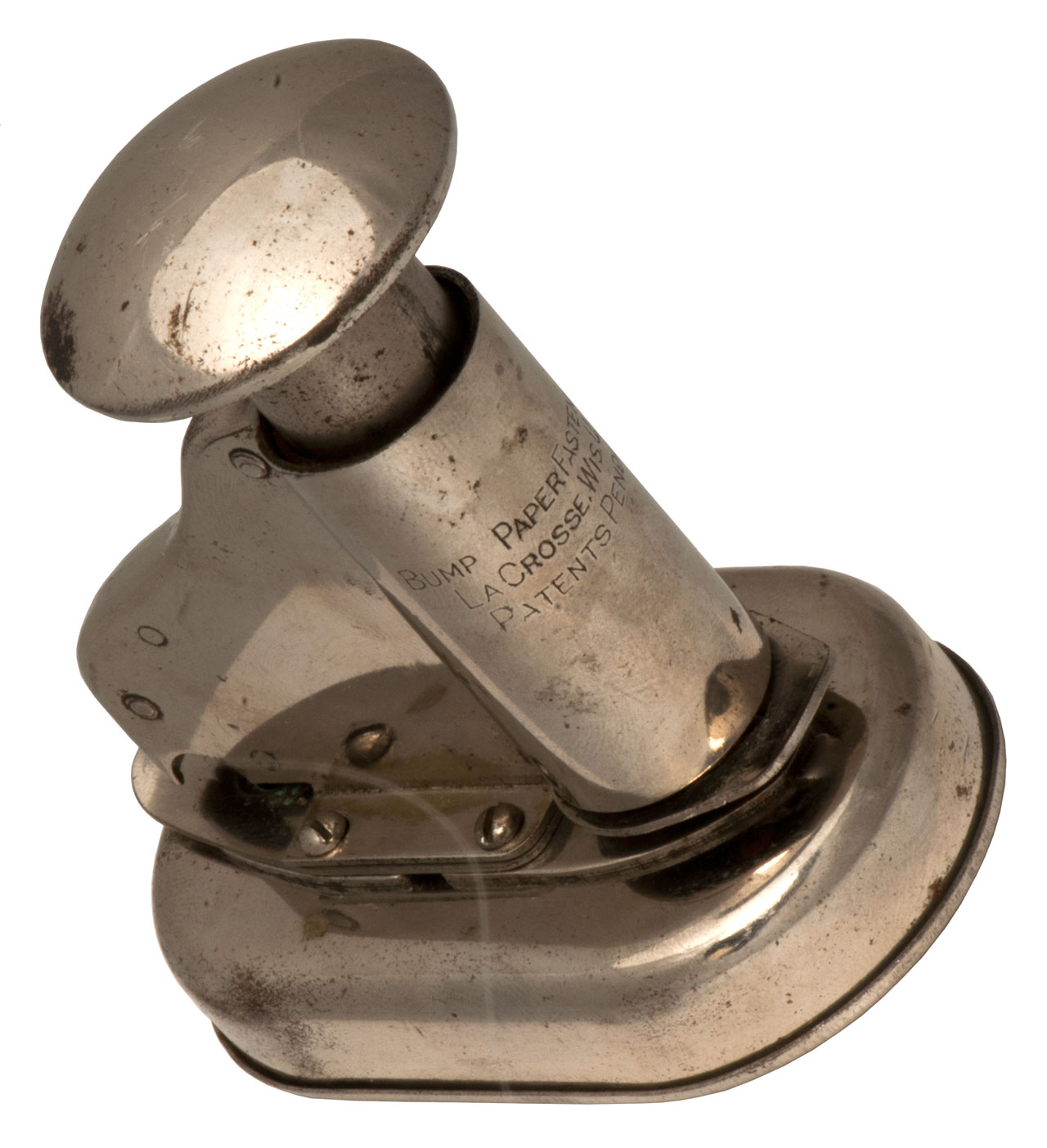
Bump Paper Fastener Co
Caution: loosening screws (9) will destroy the hole punch and/or tongue punch alignment. The alignment between the cutters and die may be destroyed if the device is dropped. Mine was non operational when received and was probably that way for a number of decades.
Photos
Fig 1
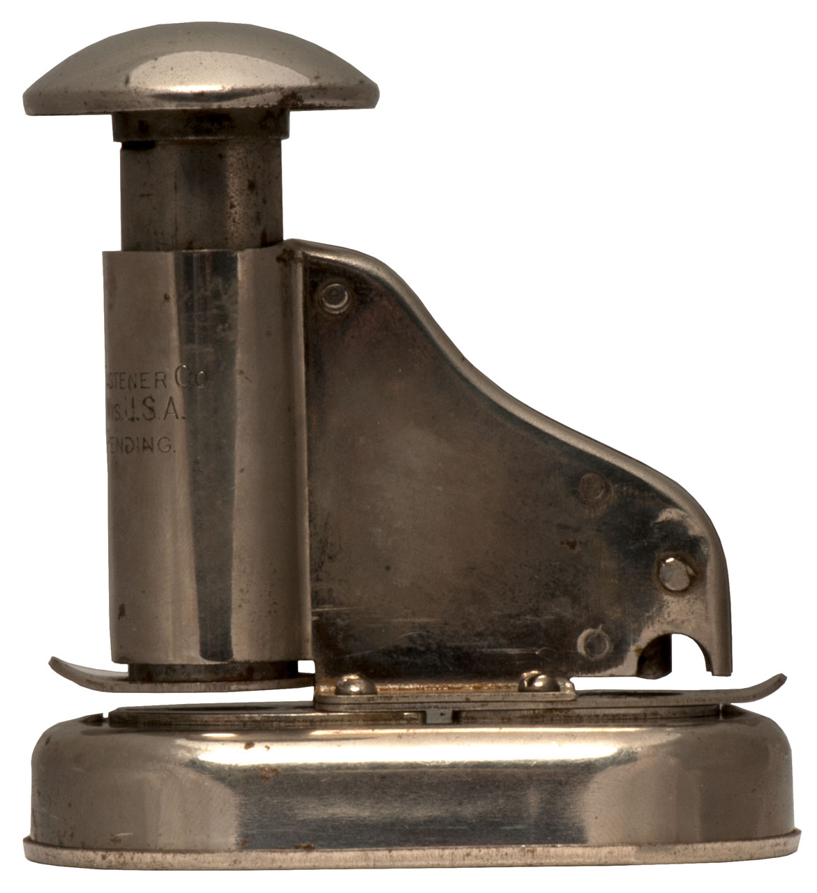
Fig 2 Side View
When received the notch at the left was not there.
You could not get the paper under the tongue punch.
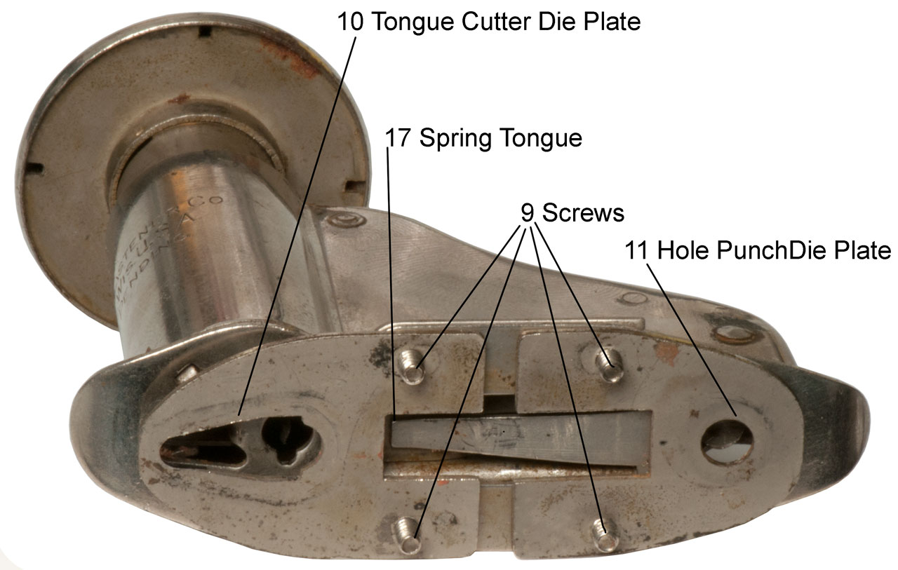
Fig 3 Critical Assembly: Needed to properly assemble in order
to get gap under tongue punch and under paper punch.
The die plates have tapped holes. Nuts are used to hold on base.
Bottom cover is a friction fit on base.
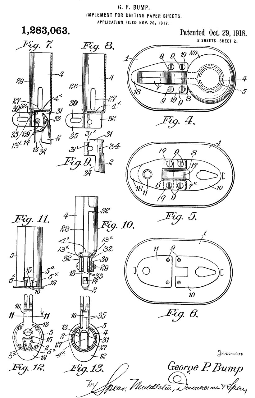
Part numbers & names match patent 1283063

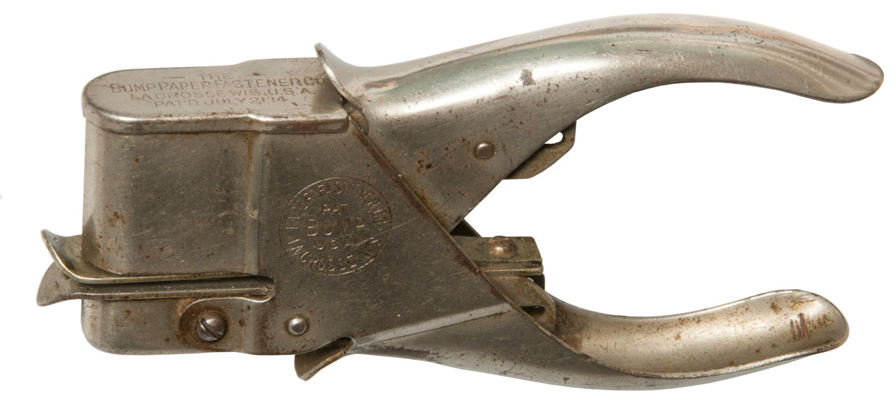
Fig 20 Bump Hand Held Fastener
"The BumpPaperFastener Co.
La Crosse Wis. U.S.A.
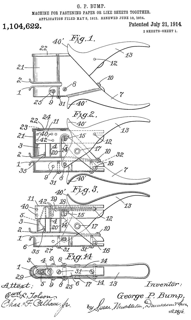
Pat'd July 21 '14" See: 1104622
1009644 Method of fastening paper sheets and the like, George P Bump, 1/2 to J.C. Hawkins, Nov 21, 1911, 493/351; 24/67R; 229/84; 493/353; 493/392 - tongue into slot (not machine, just concept)
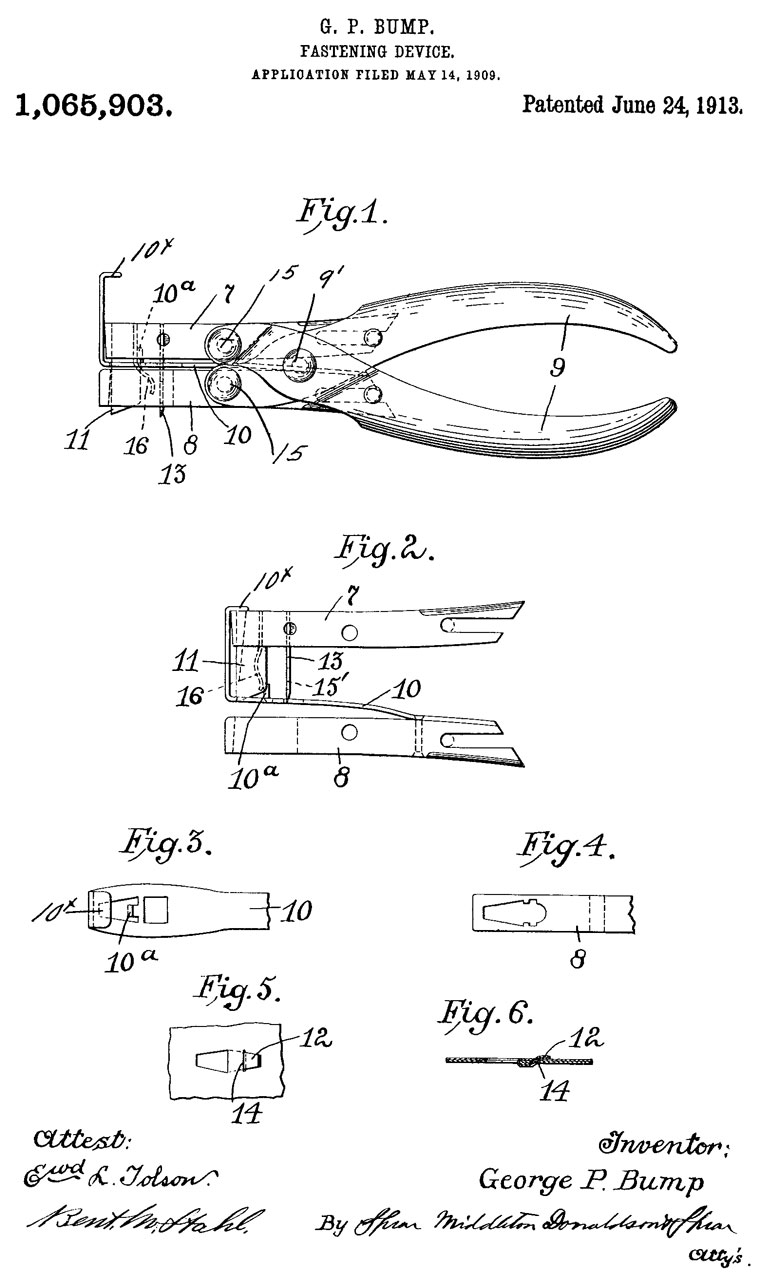
1065903 Fastening device, George P Bump, (not assigned), June 24, 1913, 493/351; 493/392; 493/353 - hand held (looks like paper punch)
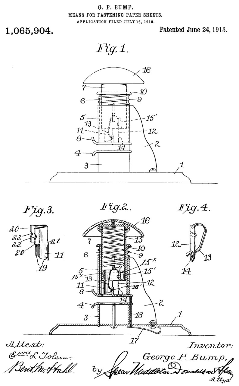
1065904 Means for fastening paper sheets, George P Bump, (not assigned), June 24, 1913, 493/351; 493/353; 493/392 - desktop mushroom head "New Model" - This in not the model shown in the photos above.
1104622
1104622 Machine for fastening paper or like sheets together, George P Bump, Bump's Perfected Paper Fastener Co, July 21, 1914, 493/351; 493/356; 493/392 - tongue into slot, paper punch model
1283063 Implement for uniting paper sheets, George P Bump, (not assigned), Oct 29, 1918, 493/351; 493/356; 493/392 - desktop mushroom head "Stand Model"
Clipless
The Clipless uses the same tongue tucked under a slit as the Bump. The patent dates are close together so not made after expiration of first patent. Improvement over the Bump since the papers are clamped prior to cutting the tongue. This should make for more reliable operation.
Apparently Clipless also licensed the Paper Welder patent. This example functions just like the paper welder, but is a new design with apparently no interchangeable parts.
Fig 1
The label is in a pocket that is part of the base casting.
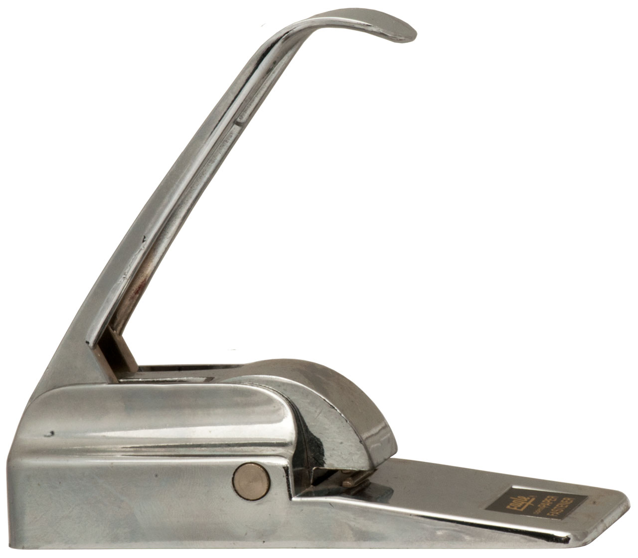
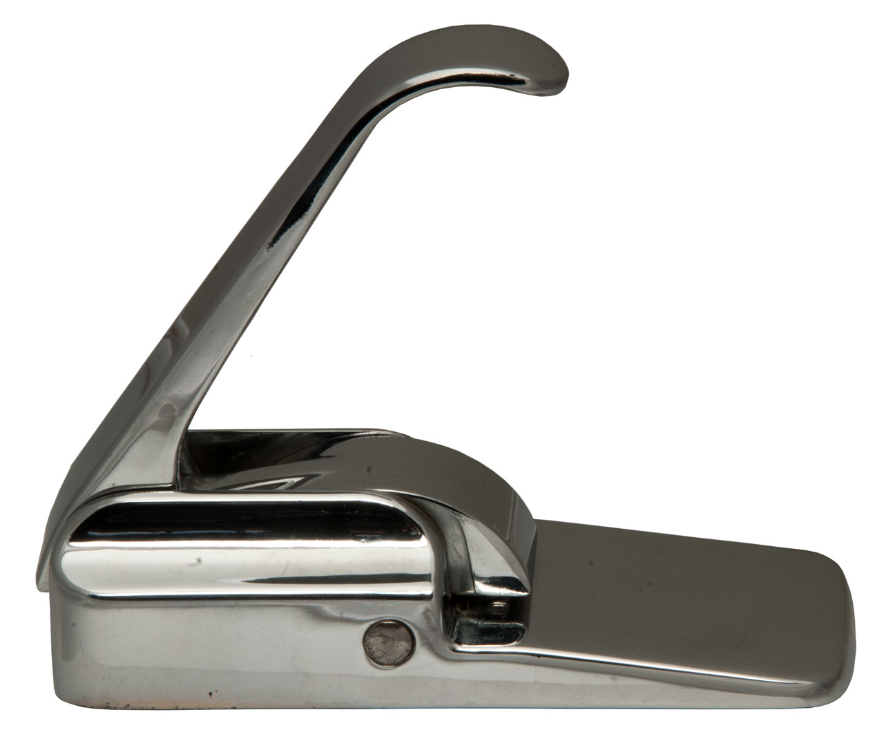
Fermafix Paper Binder
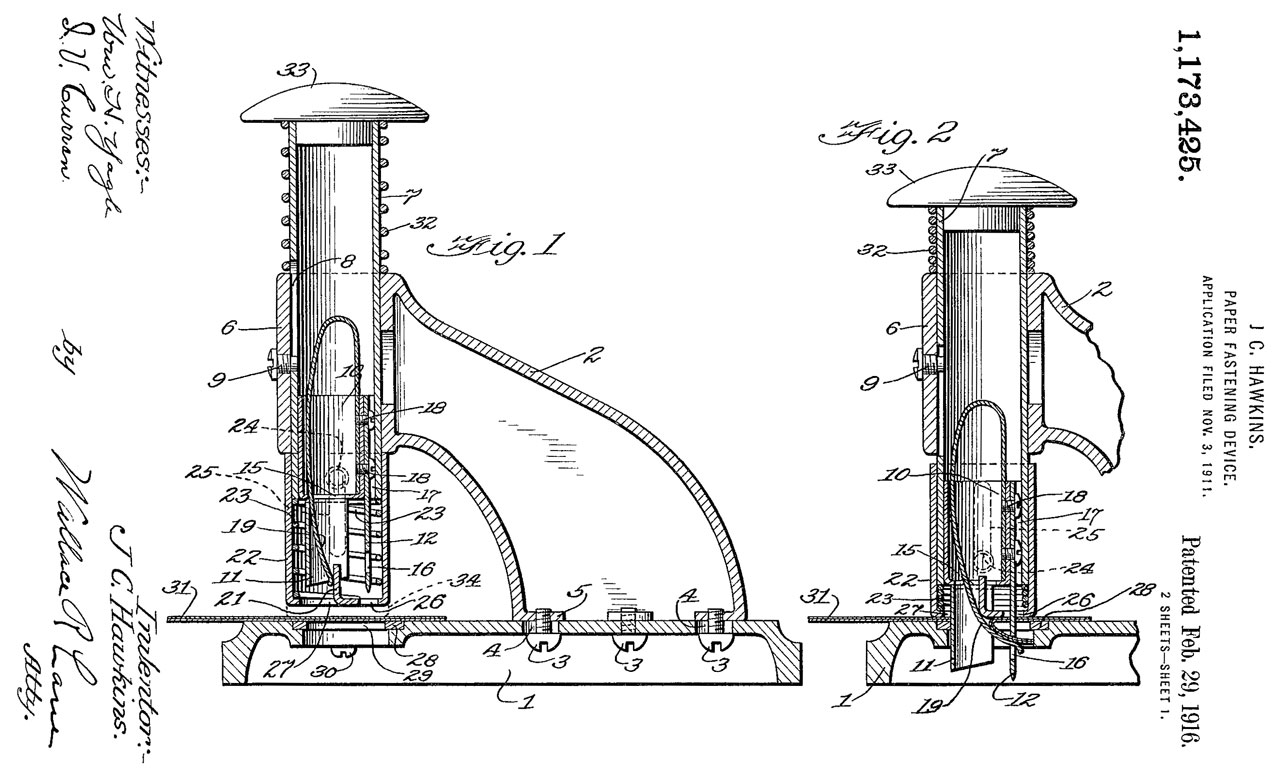
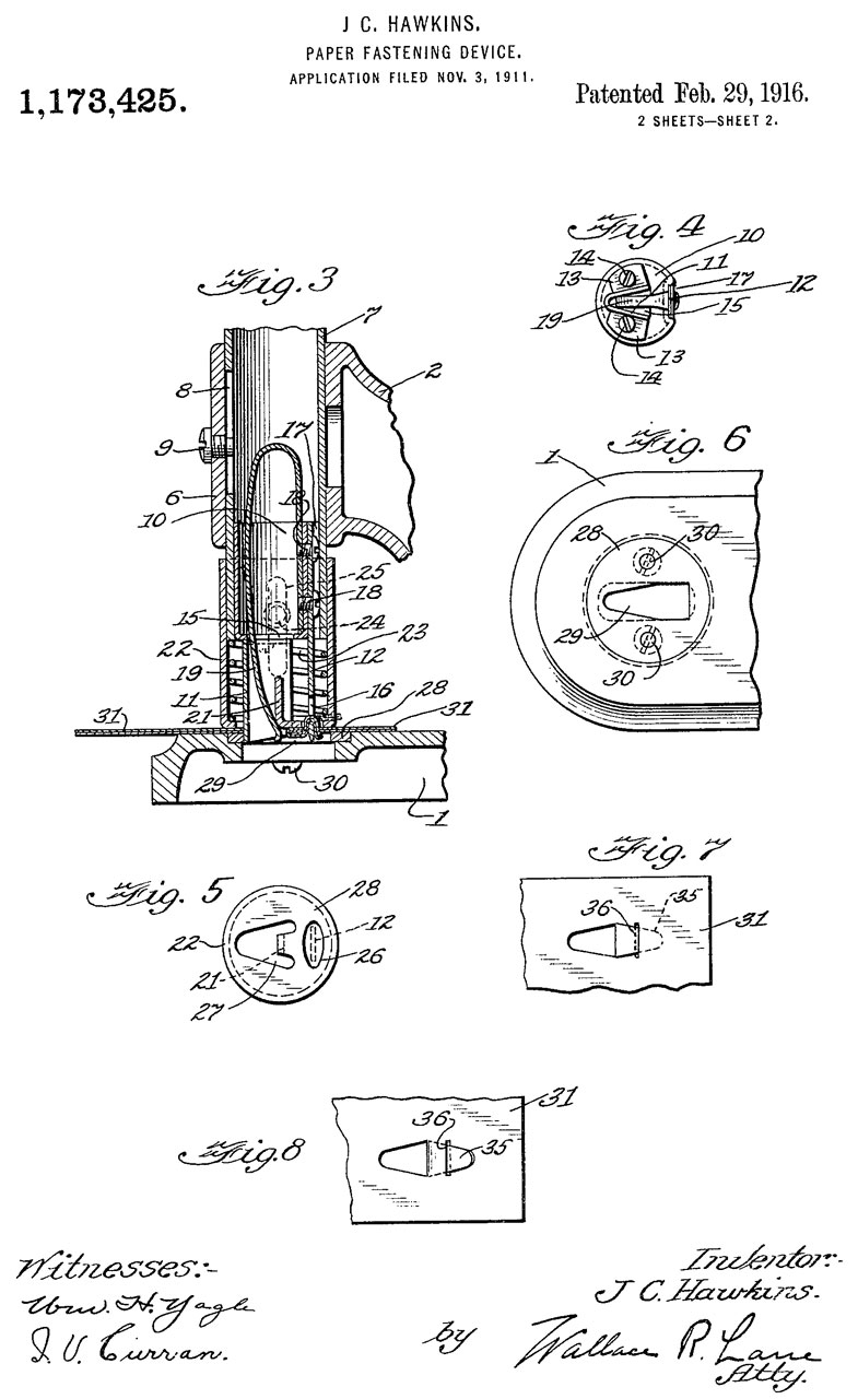
1173425 Paper-fastening device, J C Hawkins, Feb 29, 1916, 493/351; 493/392; 493/356 - looks like Bump mushroom head
1954965 Paper crimping device, William N Thode, Seiders-Mather Corp, Apr 17, 1934, 493/390; 412/29 - heavy hand crank machine that clamps to edge of table.
1960059 Paper crimping device, Charles C Mason, Seiders-Mather Corp, May 22, 1934, 493/390; 213/32R; 493/379 - heavy hand crank machine that clamps to edge of table.
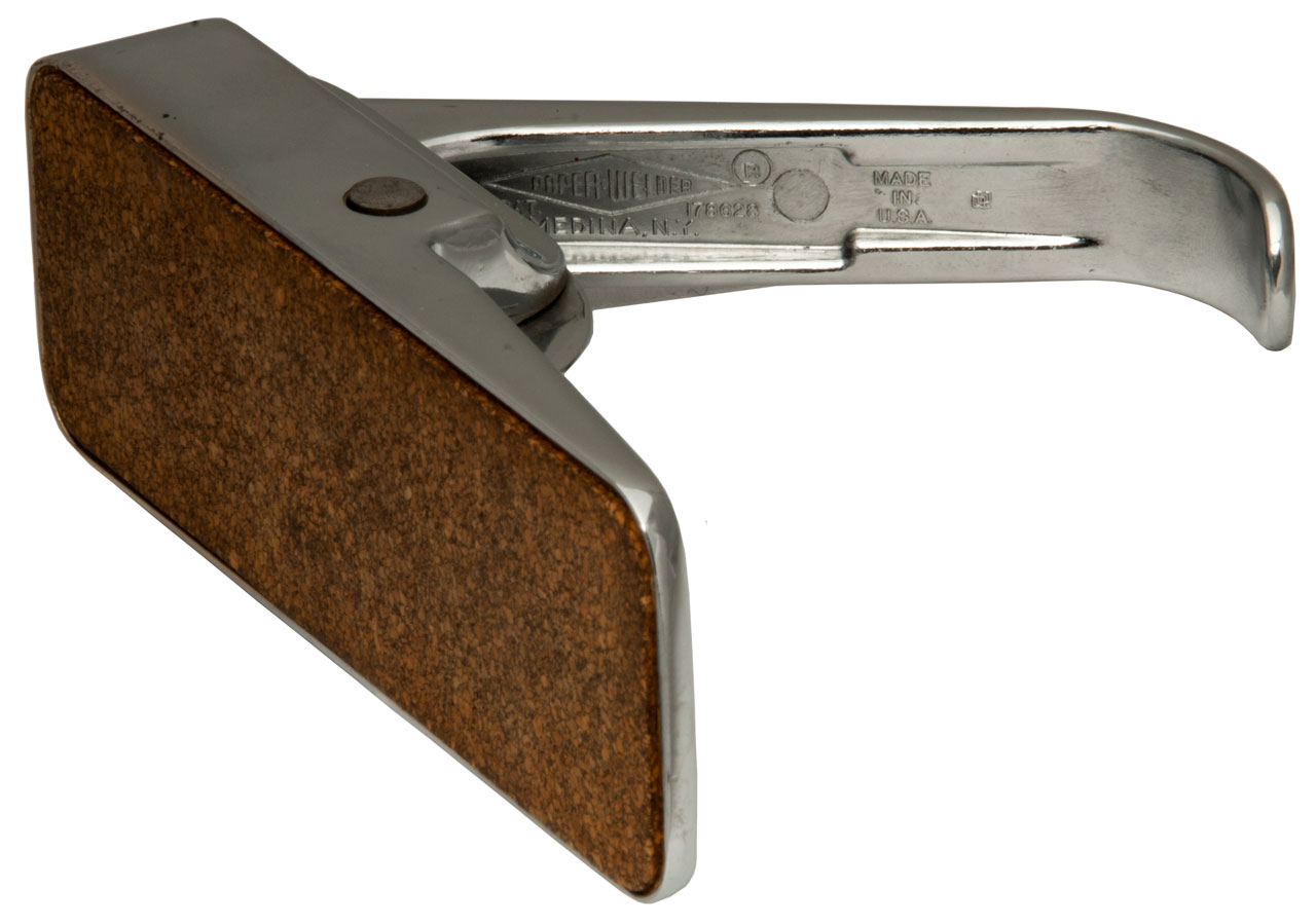
Paper Welder
Photos
Fig 1
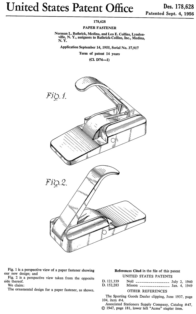
Fig 2 Paper-Welder, Des. Pat. 178628
Medina, N.Y. Made in U.S.A.
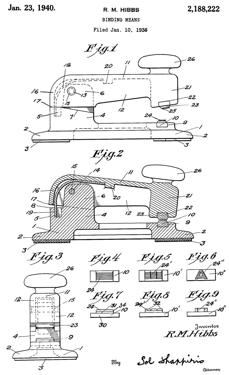
2188222 Binding means, Ralph M Hibbs, 1/2 to S.E. Lewis, Jan 23, 1940, 493/390; 101/3.1 - looks like stapler
2275111 Paper fastening and crimping press, Norman S Noll, Mar 3, 1942, 493/390 - looks like large heavy duty stapler
D178628 Paper fastener, Norman L. Bathrick & Leo E. Collins, Bathrick-Collins Inc, Sept 4, 1956,
Cites:
D121339 Paper Fastening Machine, N.S. Noll, Jly 2, 1940,
D152283 Paper Punch, W.H. Misson, Jan 4, 1949
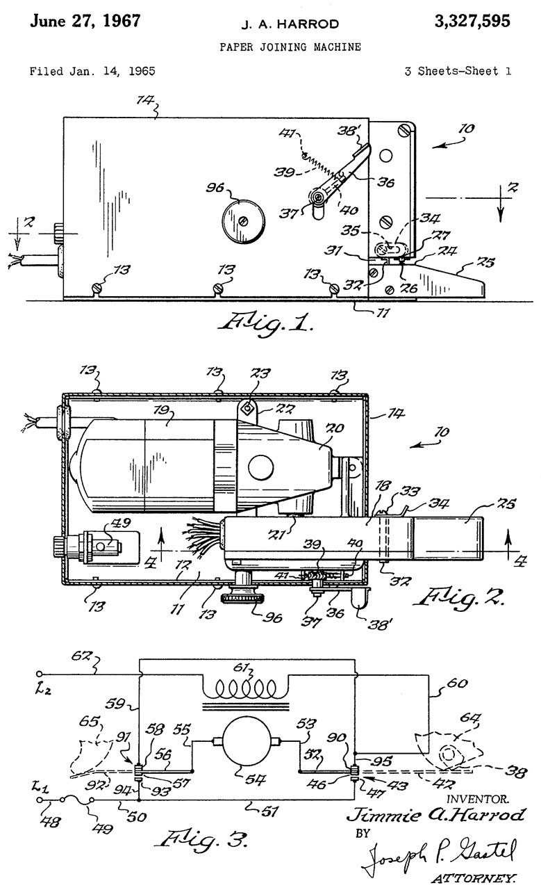
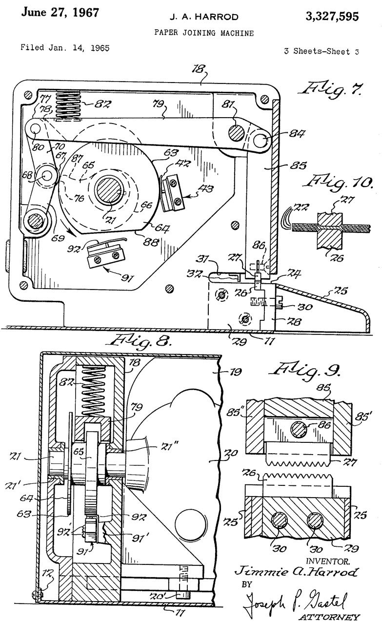
3327595 Paper joining machine, Jimmie A Harrod, PAPER WELDER Inc, Jun 27, 1967, 493/6; 83/630; 493/393; 74/38; 493/381 - electric motor drive
American Stationer - Paper Welder -
General "Paper Fastening" Patents
23322 Mode of fastening sheets of paper together, E.L. Smartmount, Mar 22, 1859, - uses what amounts to Acco pins and top clip.
58667 Paper Fastener, G.G.W. Morgan, Oct 9, 1866, - Acco type, but no top clip/plate.
66968 Paper Fastener, M.H.N. Kendig, July 23, 1867 - Acco type
Eyelets
eBay Title: Grommet Machine 3 Die (#0, #2 & #4) with 3 sizes of Grommets & Washers. under $40.
On my first try using the #0 dies and a grommet with a short shank (there are different length grommets in the size #0 bag) and a #0 washer the two pieces of paper punched and joined.
Fig 1
Button and String Closure (Staples Inter-Department Mail 50163/472993)
221359 Letter-package clasp, J.W. Ripley, Nov 4, 1879, 24/18 24/127 - metal plate with button
238605 Package Fastener, P.A. O'Malley, March 8, 1881, 24/18 24/134R 24/2 - complex plate w/2 buttons and binder
265276 Package Fastener, P.A. O'Malley,Oct 3, 1882, 24/18 24/133 - complex plate w/2 buttons and binder
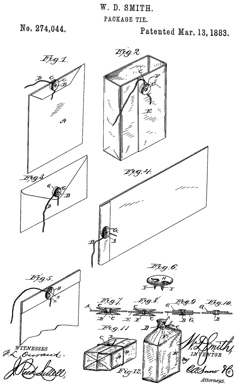
274044 Package Tie, W.D. Smith, Mar 13, 1883, 24/127 24/18 24/712.9 40/665 229/77 229/125.22 - button w/attached string that can be installed using 2 metal tabs.
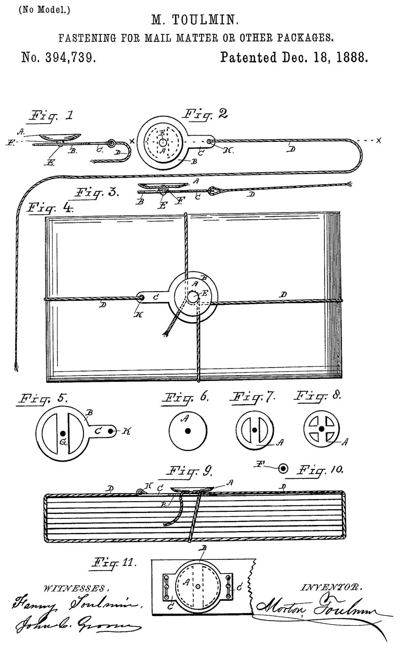
394739 Fastening for mail-matter and other packages, M. Toulmin, Dec 18, 1888, 24/18; 24/127 - stand alone button/spool with string.
Paper Clips (Wiki)
Staples (Wiki)
Patents
208789 Improvement in machines for inserting and clinching wire staples, W.J. Brown Jr., Oct 8, 1878, -
267283 Paper Fasening Machine, M. Toulmin, Nov 7, 1882 - staples where top is wider than pins. Moving flippers at bottom form pins.
1735195 Stapling device, 1929-11-12, -
Acco fasteners
These are sheet metal straps that are bent and another sheet metal part with holes at each end is put over the top. (Staples Acco 12992H)
Screw Posts
(Staples CLI 3703L)
Brass "T" fasteners
(Wiki) a brass mushroom with two brass sheet metal tails. (Staples Acco 71504)
56587 Paner Fastener, G.W. McGill, July 24, 1866, 411/457 - made all from sheet metal (no round metal head, but the same functionality as the modern version.
337182 Metallic fastener, G.W. McGill, March 2, 1886, 24/703.6; 24/96 - one of the versions has a round head.
Bulldog Clip
(Wiki) a "C" spring with a couple of jaws and levers to open.
Mechanical
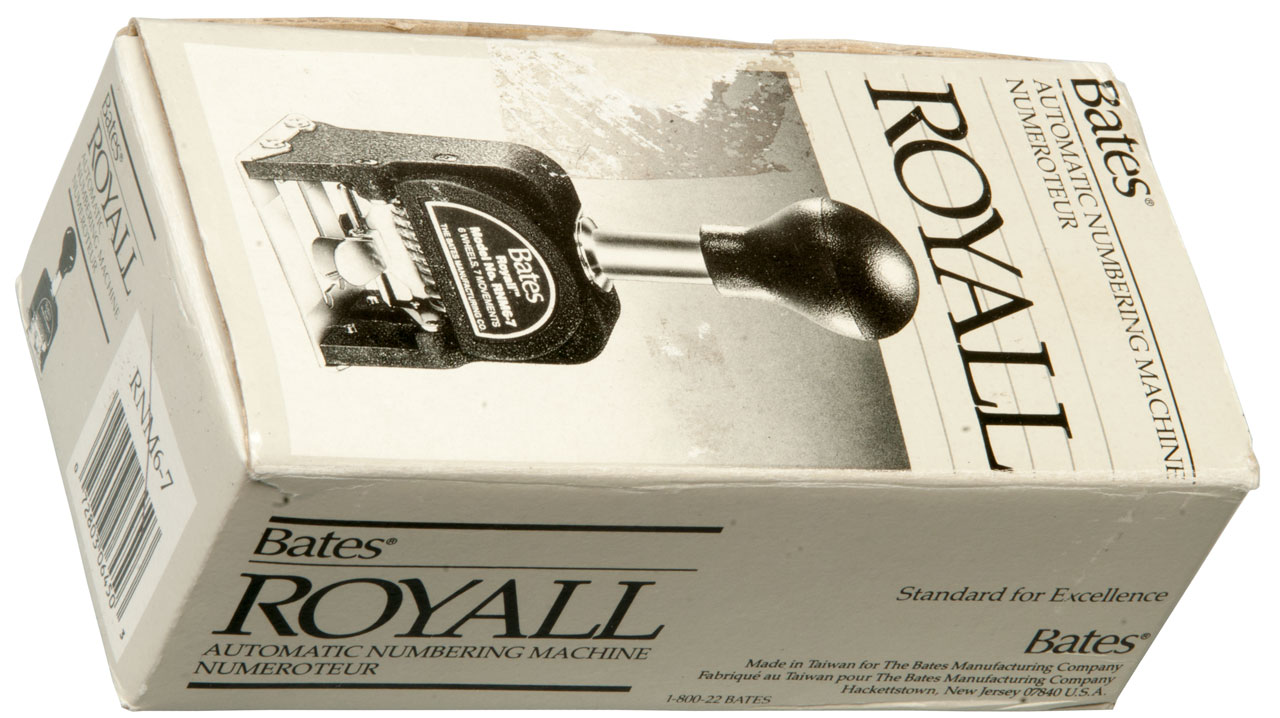
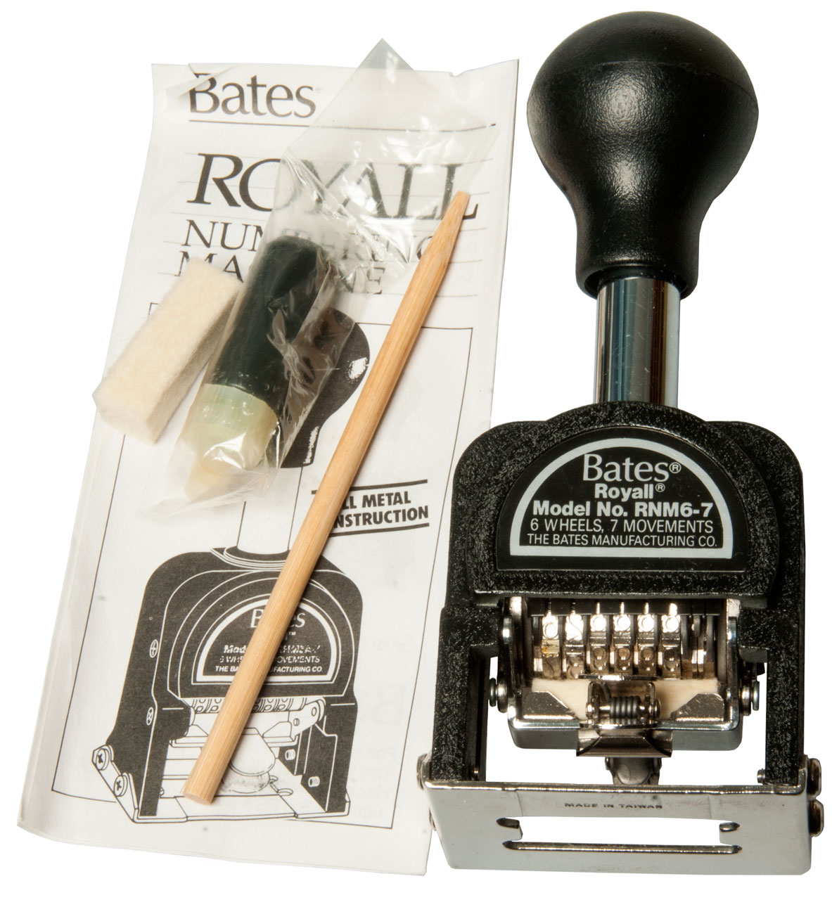
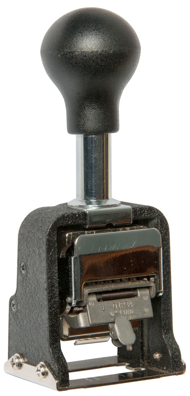
Bates Numbering (Wiki)
Photos
Fig 1
Fig 2 Ink clip below 6 wheels
Fig 3 Mode set to "0", no incrementing
Fig 4 Ink pad out to get new ink.
Fig 5 Plunger lock pressed in holding plunger down
so that the wood stick can be used to change numbers.
Fig 6 Bottom view.
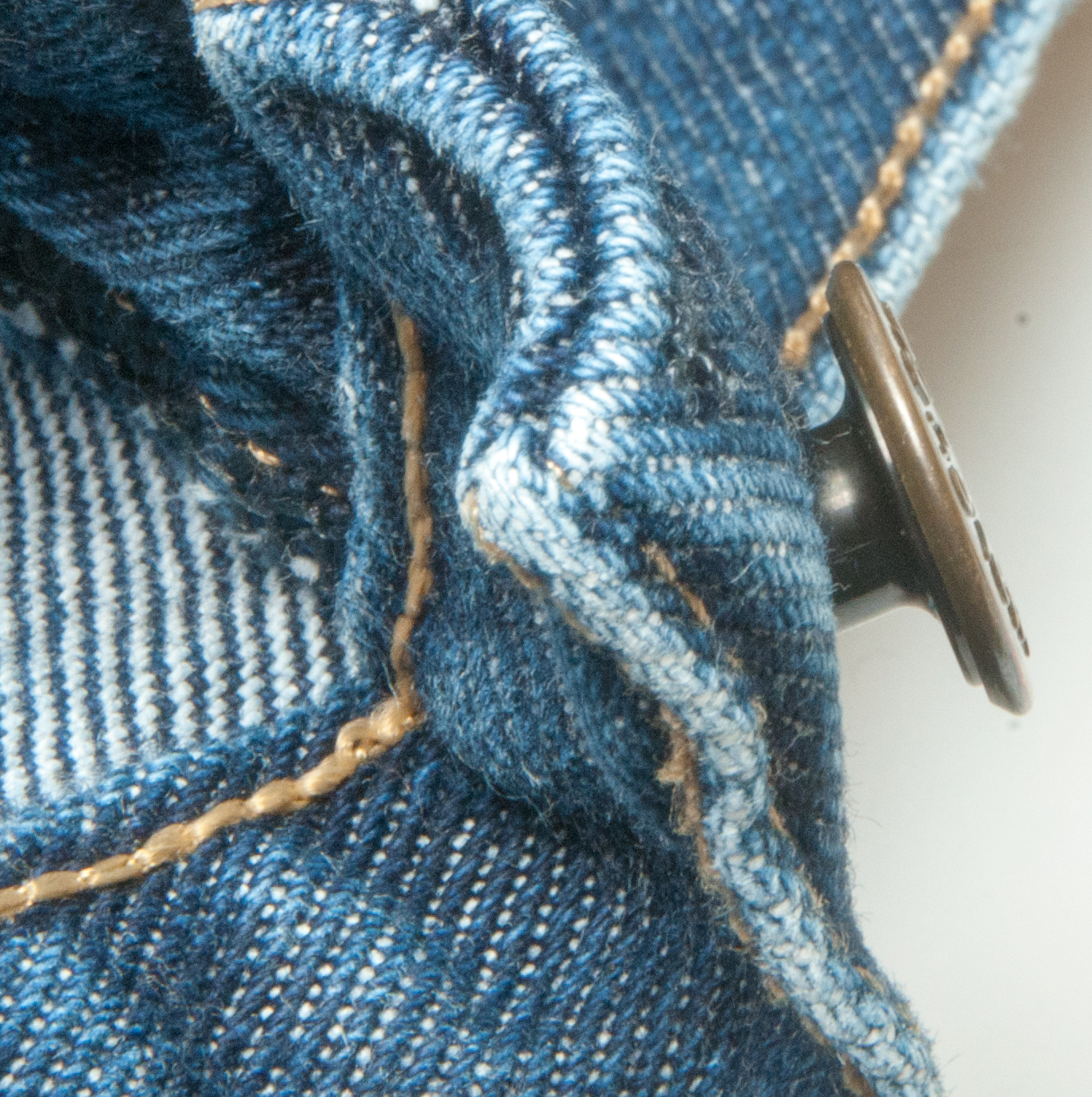
For decades I've been using normal buttons to attach suspenders to my pants. But very often a button pops off. I think it's because there's no shank to separate the button from the base material and allow a space for the leather suspender strap.
The jeans fly button shown here has a shank and that's what's needed for suspenders.
Goldstartool - Rivets - Jean Button - Text & SKU: GS-HS-JB-17mm
on order 17 Nov 2021 - next to try them.
They work great.
In the past the suspender buttons were on the inside, but since the new buttons, like the jeans button, have an image on the front,
I'm mounting the button facing out.
Failed in less than a year.
YouTube:The Best Bachelor Buttons & How to Install Them, 9:52 - search for "Welch bachelor buttons" - Welch Workwear - Buttons -
12" Bench
Top Hand Shear
5C Tool room lathes when working in the
Microwave business the shop was full of them
8" Mini Shear Break
Active Storage - shelving and box
sizes
Air Tools
Digital-Retro-Turbo-Encabulator
Drill Press used with 5C collets
Electric mains power Generators
Farm Hi Lift Jack
Geodesic Dome Connector Plates
Hints & Tips What Goes Wrong
Lathes for < 1" OD parts (5C collets)
Mini Machine Tools (Lathes and Mills) One
of my dreams
Fasteners A page made for my own use
with dimensions of common fasteners used for product design and
for looking at new
ideas for products
Measuring Tools Used mainly for
reverse engineering
Pocket Tools
Adding this section based on the YouTube by the History Guy:
Robertson, Phillips, and the History of the Screwdriver (16:24)
1:03 The idea of the screw - started out not related to fasteners about screw cutting machines. But for a better background see Wiki: Screw-cutting lathe for a progression of machines
2:08 The wheellock (Wiki) uses a screws. Uses an external "v" shaped flat metal spring . . . (there may be an internal spring as part of the wheel drive). Tthree flat head screws hold the wheel mechanism to the side of the gun and a square headed screw is used as part of a clamp to hold the flint. (not quite the description in the video). B.C.: one of the motivations for interchangeable parts (Wiki) was the desire to be able to repair guns on the battlefield rather than send them back to a gunsmith who would make custom parts to fit.
2:47
3:04 Cold Rolling threads (Wiki) was perfected in the 1880s.
223730 Machine for Rolling Threads of Screws or Bolts, H.A. Harvey, 1880-01-20, 470/68; 72/92 -3:14 At that time the heads were either external hexagon or square or internal flat slot. Then a number of internal type heads.
248165 Machinery for Rolling Screw Threads, H.A. Harvey, 1898-10-11, 72/93 -
370354 Die for Rolling Screw Threads, C.D. Rogers, 1887-09-20, 72/469 -
161390 Wood-screw, A. Cummings, 1875-03-30, 411/407; 411/919 - "It is well known that the ordinary screwhead, provided with a slot, is very susceptible to injury, caused mainly by the slipping of the screw-driver from the slot when the screw is being set home in wood or metal." "It is in the removing or withdrawing of screws that my invention proves its great utility. Screws that have been long embedded are very difficult to move by the use of an ordinary screw-driver, it invariably slipping from the slot, repeating the same until it is utterly impossible to start the screw or to obtain a hold in the slot. My invention completely eradicates this trouble,- and the screw is readily withdrawn at the first trial."5:56 P.L. Robertson's 1907 Canadian patent (Wiki) is for a screw head with an internal square shape and a taper. Worked better than slotted heads when painted over. It also could be cold formed (Wiki), i.e. very economical to manufacture. Fisher body works in Onterio Canada used them for Model T (Wiki) chassis building. (B.C.: Can't find a mention of Fisher body in Canada). Also with a different design screw of the Ford Model A (B.C.: It's not clear if this was the early (Wiki) or late (Wiki) Model A).
B.C.: The reason for this is that most flat blade (-) screwdrivers have a wedge shape and "cam out". Gunsmith screwdrivers are hollow ground precisely to avoid this problem. The faces of the driver bit are either parallel to the slot or even have a reverse wedge, i.e. slightly wider at the bottom of the slot.
CA103387A Screw Nail, P.L. Robertson, 1907-01-29,10:04 Thompson invents what's now called the Phillips head.
1908080 Screw, J.P. Thompson, H.F. Phillips, 1933-05-09, 411/403; 16/DIG.39; 470/9; 411/919; 470/60 - used tapered cruciform shaped hole making the head easy to make and strong.13:36 There's still a heated debate over which is better Robertson or Phillips.
1908081 Screw Driver, J.P. Thompson, H.F. Phillips, 1933-05-09, 81/460 -
2046837 Means for uniting a screw with a driver, Henry F Phillips, Phillips Screw Company, App: 1934-07-03, Pub: 1936-07-07, 81/460; 411/404; 411/919 - "Another object of the invention is the particular angular formation of the walls of the recess in the screw with respect to the angular formation of the working end or bit of the driver to establish a wedging engagement between the two when united. This same angular formation of both elements is especially designed to also create what might be termed a camming action during the approach of these angular faces toward one another with respect to any substances which might have become lodged within the recess of the screw. It has been found by experiment that a downward thrust of the bit into the recess will instantly dislodge any substance within the recess by causing it to move upwardly and outwardly over the walls of the recess."
B.C.: This use of the term camming is closely related to the action that tends to push the driver bit away from the screw head.
"Such failure of the slotted screw to retain the blade-driver, especially in power driven operations, is not only dangerous to the operator, but is likewise, always injurious to the work, especially in the construction of furniture and other types of work wherein the elements to which the screws are being applied become badly mutilated 5 when the power driver leaves the slot, usually during high speed operation of the driver which is most diflicult to stop in time to prevent injury to the work."
The GM 1936 Cadalic (Wiki - see In 1934, Henry F. Phillips (Wiki) introduced).
14:02 "That ability to cam out actually offers an advantage for manufacturing. With a Phillips head screw when the machine head sets the screw it will cam out (Wiki) and that keeps it from over driving the screw."
B.C.: This is wrong. Once a non torque limited Phillips driver causes the bit to cam out the screw head will be destroyed. This is why Pozidrive (Wiki) and Torx (Wiki) are now commonly used where power driven drivers are used.
2046837 Means for uniting a screw with a driver, Henry F Phillips, Phillips Screw Company, 1936-07-07 - no patents cited, but cited by 58 other patents
2474994 Screw socket, Joseph J Tomalis, American Screw Co, App: 1942-12-30, Pub: 1949-07-05, 411/404; 81/460; 411/919 -
Update
The ECX screw (Wiki) used on US household electrical outlets, switches and light fixtures is a combination of Robinson, Philips and Flat Blade heads. Made by Klein (C1 & C2) and Milwaukee (ECX #1 & ECX #2).
For Pencils see Stock Ticker Patents\Pencils.
755917 Pencil-sharpener, Edward L McDivitt, App: 1903-12-15, Pub: 1904-03-29, -
The Handy "Little Shaver" Pencil Sharpener patented March 29, 1904
Uses a single edge razor blade (Wiki), hence the moniker "Little Shaver".
I don't think the reinforced single edged razor blade shown in the photo would have been available
at the time the "Little Shaver" was introduced. That's to say it probably was based on the use of a non reinforced single edge blade which would have been more flexible and that means it probably did not work very well.
Single Edge Saftey Razor Blade
770767 Safety-razor, Merrick A Mihills, App: 1903-12-28, Pub: 1904-09-27, - this has a reinforced single edge. There were prior single edge razor blades but they were not reinforced.
788820 Safety-razor, Russ J Christy, App: 1904-10-20, Pub: 1905-05-02, - single edge, not reinforced but would work in Little Shaver.
794934 Safety-razor, Leonard B Gaylor, App: 1904-12-21, Pub: 1905-07-18, - single edge, not reinforced but would work in Little Shaver.
991147 Safety-razor, King C Gillette, (not assigned), App: 1905-01-18, Pub: 1911-05-02, - both single (not reinforced) and double edged.
850183 Safety-razor, Jeremiah Reichard, American Safety Razor Co, App: 1906-03-05, Pub: 1907-04-16, - reinforced single edge blade. "The blade E consists of a thin strip of sheet-steel, one edge of which is sharpened, as ath, to form the cutting edge, ind the opposite edge or rear edge of the blade is embraced by a substantially U-shaped metal strip G, which forms a stiffener and back for the blade and is of such dimensions that when the blade is inserted between the top of the casing and the loop-shaped holding-Spring B the closed outer edge of this strip G rests against the inner surface of the loop-shaped spring at its bend, and the shoulder g, formed by the bottom front edge of said strip, rests against the projections H on the upper Sur face of the top of the casing."
826837 Pencil-pointer, Albert B Dick, AB Dick Co, 1906-07-24, -
from eBay seller MSTIQUES: Automatic Pencil Sharpener - each pass of a blade (there are 3 blades) rotates the pencil, then shaves the point.
832054 Pencil-sharpener, Essington N Gilfillan, 1906-10-02, -
889056 Pencil-sharpener, Charles C Spengler, Automatic Pencil Sharpener Co, 1908-05-26
998044 Pencil-holding means for pencil-sharpeners, Charles C Spengler, Automatic Pencil Sharpener Co, 1911-07-18, -
Spring fingers hold pencil.
Gear at bottom allows the tip of the cutting blade to rotate pencil prior to each cut.
GB191004951 Improvements in Pencil Sharpeners, Emile Hertz Klaber, Samuel Whitehead, 1910-08-04, -
Maybe: Roneo Automatic Screw Cutting, or Dandy, or Wizard
Wizard by Automatic Pencil Sharpner a division of Spengler-Loomis Mfg Co.
The turret has 6 holes for different diameter pencils.
756287 Pencil-sharpener, Frank M Robinson, 1904-04-05, - crank on big gear (not needed)
819104 Pencil-sharpener, John A Webster, 1906-05-01, - angled cutters, chip drawer
839806 Pencil-sharpening machine, Frederick Edward Vesey Baines, 1907-01-01, - angled single cutter (poor)
1204604 Pencil-sharpener, Charles C Spengler, Spangler Brothers, 1916-11-14, - Pencil feed
1280323 Pencil-sharpener, Charles C Spengler, Automatic Pencil Sharpener Co, 1918-10-01, - can replaces drawer
1283584 Pencil-sharpener, Charles C Spengler, Automatic Pencil Sharpener Co, 1918-11-05, -
------------------------- newer than unit in photo -----------
1722771 Pencil holder for sharpeners, Charles C Spengler, Spengler Loomis Mfg Co, 1929-07-30, -
1280323 Pencil-sharpener, Charles C Spengler, Automatic Pencil Sharpener Co, 1918-10-01, - similar to the very common hand crank type with two cylindrical cutters.
3227140 Pencil sharpener, Robert J Brand, Apsco Products, 1966-01-04, -