When looking at the H.F. radio
systems I have in relation to the the
TCI 651T antenna it seems
that there are better choices.
The URC-113 H.F. radio based on the
PRC-104
uses the
AM-7148 power amplifier that
only can drive a wire (no coax output).
The RF3200ET is a 125 Watt radio that will drive the TCI 651T
antenna. (by not using the antenna coupler).
The GRC-193 is a 400 Watt radio (switchable to 100 Watts) that
uses the RT-1209() R-T as used on the
PRC-104
&
GRC-206.
The PRC-138 would be great, but it's expensive. I've heard
the following power amps work with the PRC-138:
Model
|
Power
|
Nomenclature
|
| RF-5030 |
20
|
Amp/Coupler
|
| RF 5031 |
125
|
Amp
|
| RF-5033 |
150
|
Amp |
| RF-5034 |
400
|
Amp |
| (RF-5031
drives 10221-6100) RF-3230 |
1,000
|
Amp |
Overall Systems
When the Marine Corps GRC-193 is mounted in a vehicle the overall
system gets a new nomencalture.
UYQ-3 Direct Air Support Central
Marine Corps Air/Mobile Direct Air Support Central (DASC)
mounted in a shelter (S250? What else is in there?)
Includes the VRC-83 hi-power version of the PRC-113.
MRC-138
When in the
M151 Jeep or
HMMWV. Includes the VRC-83 hi-power
version of the PRC-113.
Coupler to the Back for use
with Whip antenna on Jeep.
|
|
Front
|
Back

|
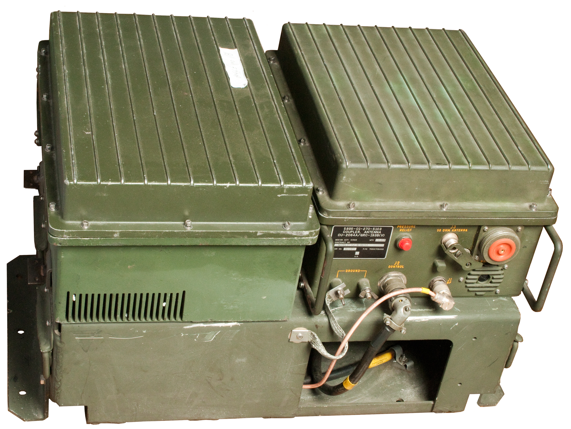
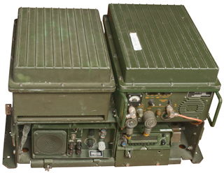
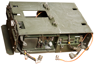
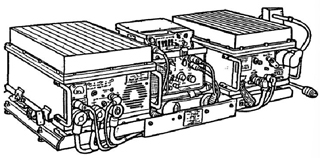
One box contained the MT-6232 with
the Audio Amp and the RT-1209 installed along with the
interconnecting cables.
The other box contained the RF Amp and Antenna Coupler.
MT-6232, AM-6879,
RT-1209
|
|
|
 |
|
|
51 lbs.
|
Package 61 lbs.
|
Packing 10 lbs
|
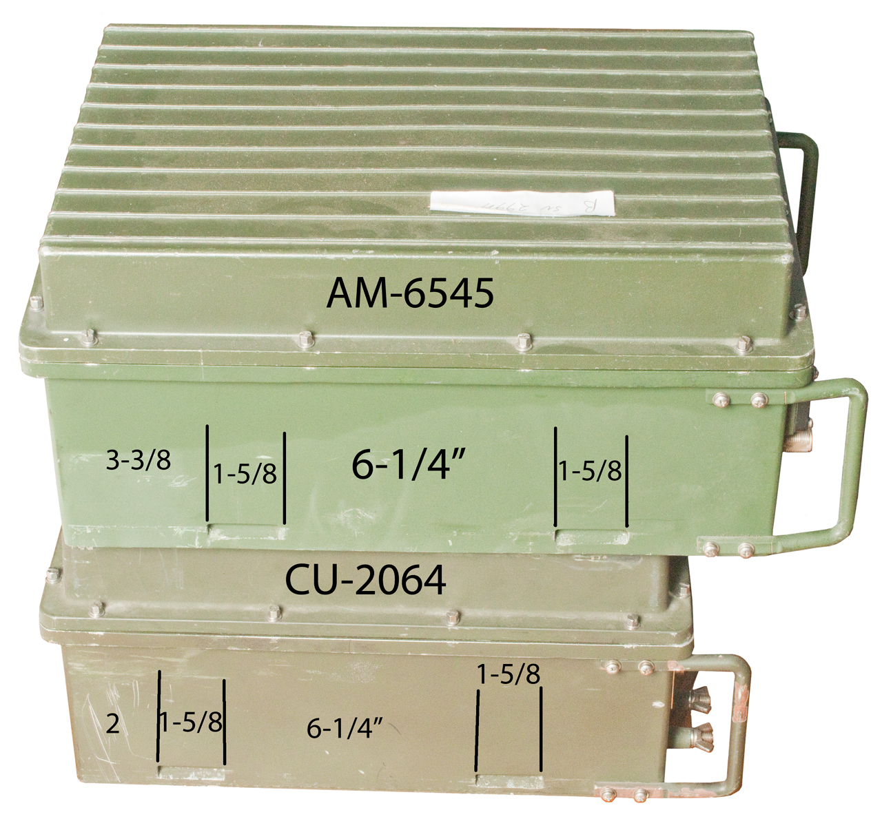
AM-6545B, CU-2064A
|
|
|
 |
 |
|
54 lbs.
|
40 lbs.
|
Package 101.2 lbs.
packing 7.2 lbs.
|
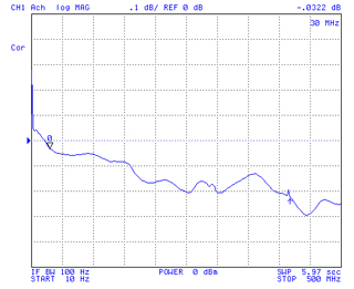
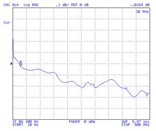
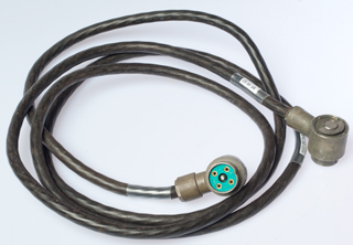
DC input from
PP-6224. Antenna coax connection
(not HV connection) to
TCI651
(which has very low return loss using the
RF3200ET).
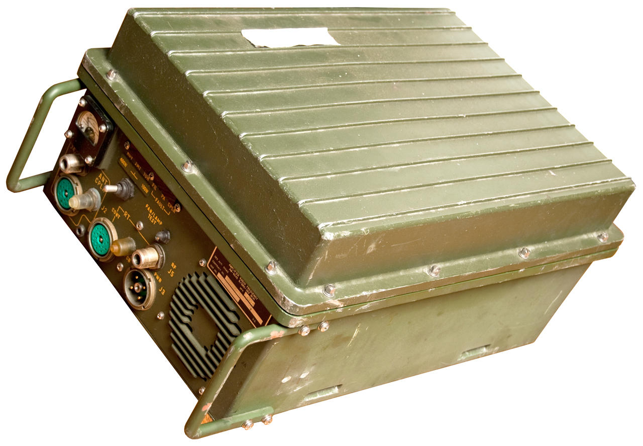
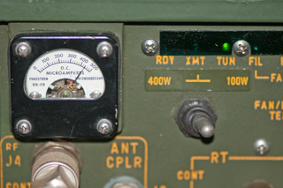
Power Amp set to 100 Watts which is well within the capability of
the PP-6224 DC power supply.
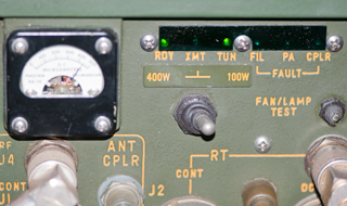
RT1209A set to 3996 USB VTR.
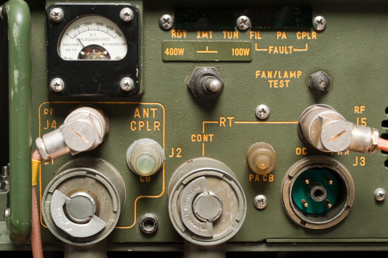
At power on there is beeping in the loudspeaker and the
Tune light is on
as everything warms up.
Pressing the FAN/Lamp Test button turns on the fans and
all 6 Test Lamps light.
|
|
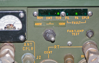
After about a minute the beeping stops and the RDY and TUN
lights are on.
Unit warmed up and ready.
|
|
Pressing the mike PTT
starts the tune operation and XMT & TUN are on
this lasts only about 5 to 10 seconds.
|
|
TUN and PA Fault lights are on and there a lot of beeping.
PP-6224 is running at about 4 amps.
|
|
The
most likley cause of the problem is a poor electrical
connection. See Hints and
Tips: What Goes Wrong
|
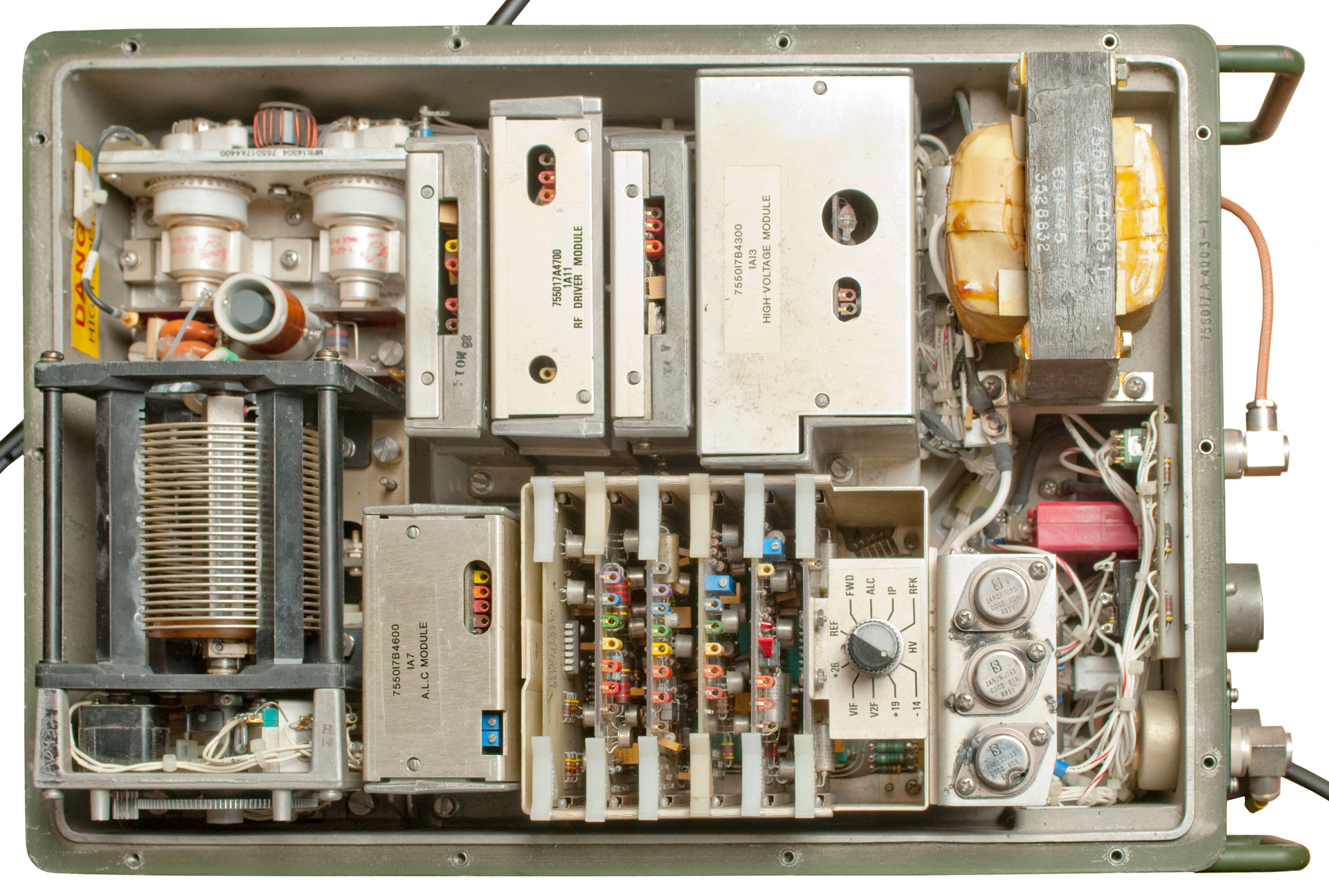
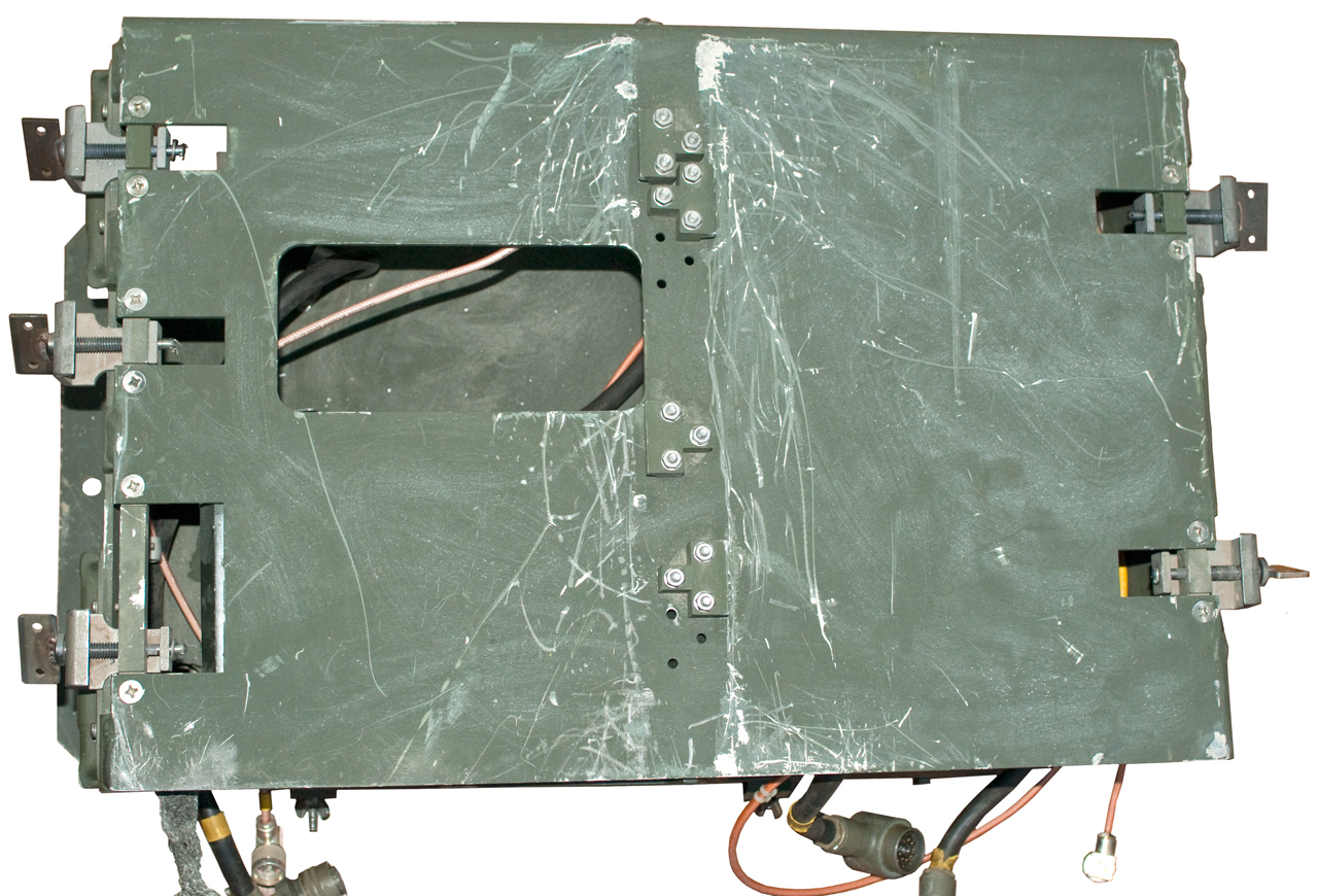
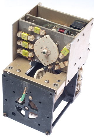
Fig
PU4 AM-6545 Top Inside

|
AM-6545 Inside Lid
|
Pulling
and reinstalling the 6 PCBs (1A1 to 1A6) and the tank
assembly (1A8) did not solve the problem.
The tank assembly does NOT move when tune is under way so
maybe the servo (1A5) circuit has a problem.
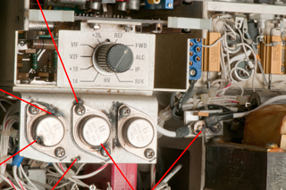
|
Main Test Points
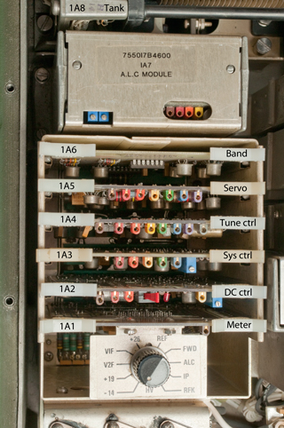
|
1A8 Tank Assembly
|
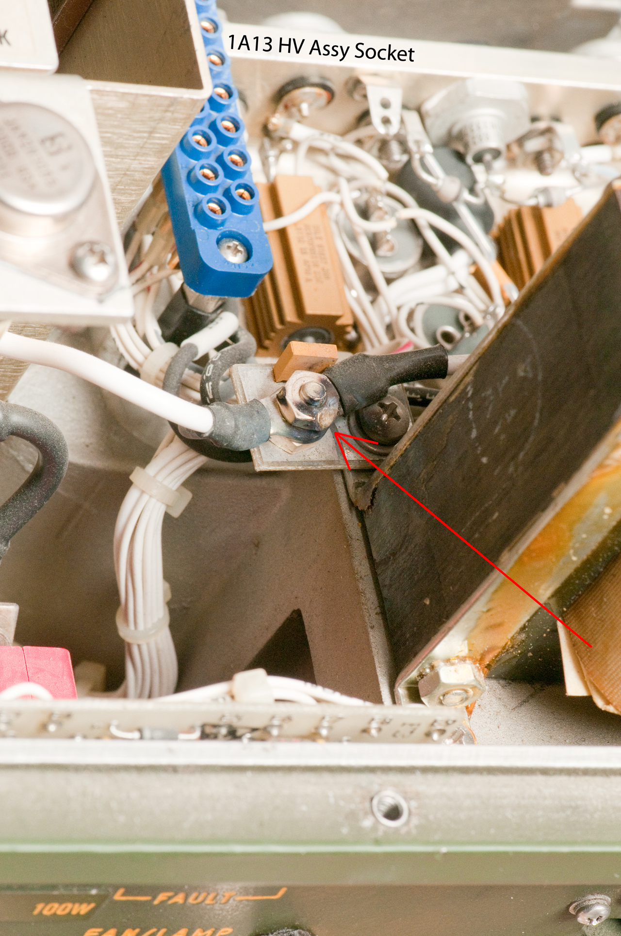
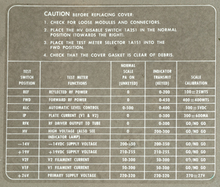
Prior to making the meter
readings I noticed that a nut holding a white wire from
the transformer had been melted,probably by a short to
ground. What is the function of that wire?
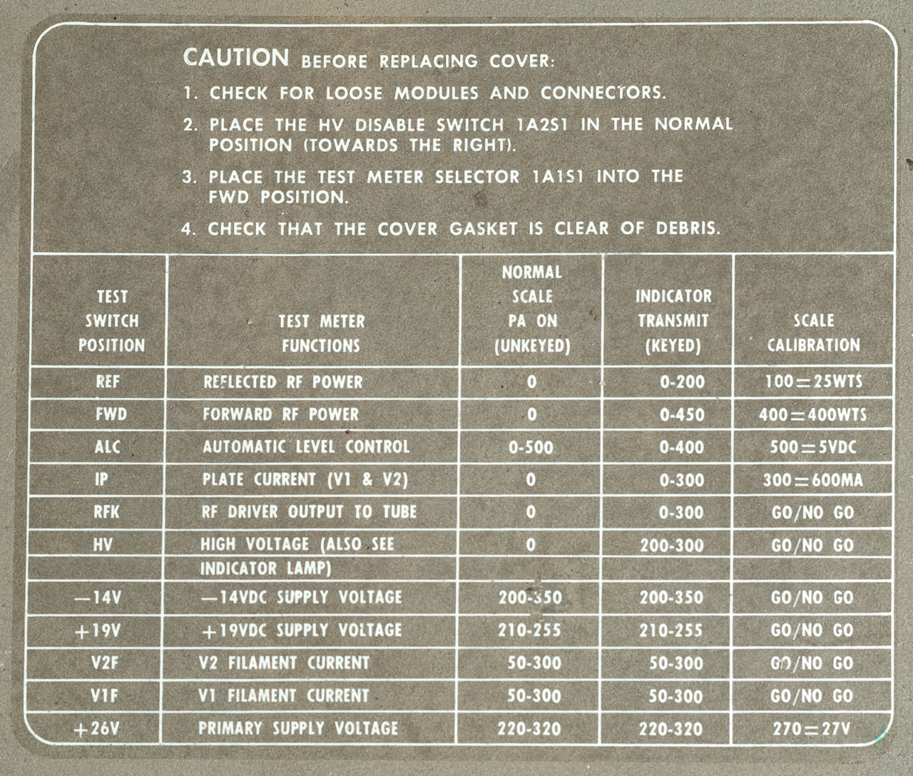
Meter Readings
Switch
|
Rx
|
Meas
|
REF
|
0
|
60
|
FWD
|
0
|
60
|
ALC
|
0-500
|
430
(-60=370)
|
IP
|
0
|
60
|
RFK
|
0
|
60
|
HV
|
0
|
60
|
-14V
|
200-350
|
500
(-60=440)
|
+19V
|
210-255
|
400
(-60=340)
|
V2F
|
50-300
|
100
(-60=40)
|
V1F
|
50-300
|
300
(-60=240)
|
+26
|
220-320
|
340
(-60=280)
|
|
Aapped Nut photo taken
after removing 1A13 HV module.

|
The 1A5 Servo pwb test
voltages are:
Test
Point
|
Rx
|
Meas
|
1
Bias
|
+12
|
6.3
|
2
Enable
|
+6.1
|
0.9
|
3
B enable
|
-1.14
|
-1.4
|
4
A enable
|
-1.1
|
+2.9
|
5
+19
|
+19.5
|
+30
|
6
A
|
0
|
28
|
7
B
|
0
|
0
|
At this point there was a flash of light from the 1A13 HV
module, smoke and smell. |
|
Now
to open the 1A13 HV module and see what burned up.
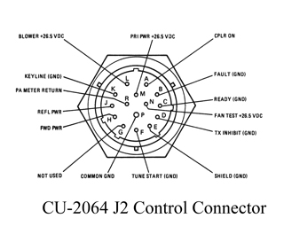
It was R12 1 Ohm 1/2 Watt in series with the emitter of Q1
(2N3055). The collector is tied to the +26.5 buss
and R12 is in series with the HV Start pin M on the
interface connector.
|
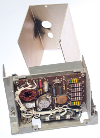
Input Voltage Regulator
Bracket
There are a number of places where the main input power
supply has been used like an arc welder. Two of the
2N3055 cans have holes and the bracket and a number of
strike markes. You can also see this in the first
top inside view above (Fig PU4)
|
These three 2N3055 transistors are:
Q3 - 19V regulator pass transistor (2 holes)
(explains meas)
Q4 - Filament regulator for V1 (1 hole)
(explains meas)
Q5 - Filament regulator for V2 (no holes)
|
What Went Wrong
As the final power tubes age they have lower gain and that
lets the plate voltage rise. When the plate voltage gets
high enough an arc from the plate to other parts of the tube
(including the cathode/filaments) burns out the tubes and the
circuitry associated with the power tubes.
If the power amp had received regular maintenance where the
plate voltage was kept adjusted there would not have been a
arc over.
But this seems to be a common problem with high power RF amps.
Eimac app note 17 recommends adding a resistor in series with
all the high voltage terminals to limit the energy in any arc
to 4 Joules.
Replacement tube ideas (may require different filament
voltage or mechanical heat sinking:
Y621B (stock tubes no longer available)
8873 (replacement, but different filament voltage)
8874
3CX-800A7 - 3CPX-800A7
8660AS
4CX-250B
4CX-300A
RT-1209 Receiver Exciter
RE-1209
NSN: 5820-01-069-2368
RT-1209A
NSN: 5820-01-270-5099
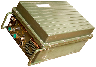
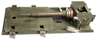
AM-6545A/GRC-193A Amplifier 100 or 400
Watts Harris
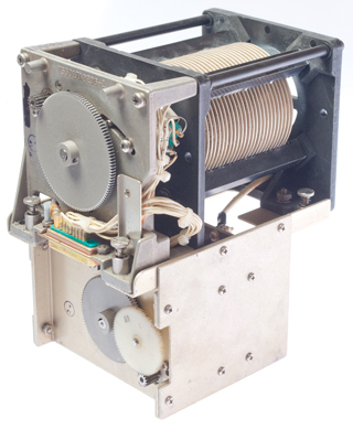
Motors
Like the CU-2064 Antenna Coupler, this R.F. Amplifier also has
motors and needs to be Lubed.

|
Note the DC input
connector, J3, has a central threaded hole, not the
common DC input connector male threaded post.
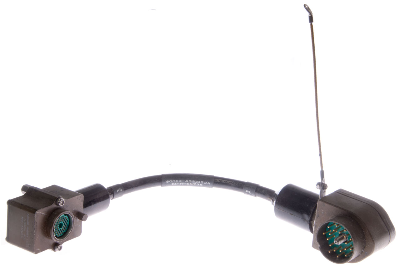
See the CX-4721 cable
photos.
This is the same DC Input connector as used on the GRC-106. A cable with a
mating connector is the CX-10071/U, but is has bare
wires at the other end for connection to a battery.
A & B = + 26.5 VDC
C & D = Ground
The meter can read 11 different things depending on an
internal switch setting.
|
Starting with a cable that has the connecotr for J3 (UW1220FA
17) has four female sockets and male threaded center anchor.
The wire colors are:
Func
|
AM-6545
J3 Pin
|
Wire
|
P.S.
(J3 or J4)
|
+26
|
A
|
Red
|
B
|
+26
|
B
|
Org
|
B
|
Gnd
|
C
|
Brn
|
A
|
Gnd
|
D
|
Blk
|
A
|
The connector to mate with the PP-6224 Power Supply is the
MW10M(M)A17 which is the standard military vehicle 24 V power
connector with male pins and a female center threaded anchor.
 |
To get access to the solder lugs:
Remove top and bottom clamp rings using special spanner
tool.
Pull center locking assembly out.
The stock wiring of the CX-4721
is:
A: Black
B: White
C: Red
D: Green
Liquid Wrench helped in getting the old cable out of the
connector shell and free up the brass ferrel that the
nut compresses.
Removed the old yellow label since the new shrink tube
would not pass over it.
Marked:
|
| On
the PP-6224 two rear output connectors (J3 or J4) A =
Gound, B= +28 VDC. Pins C and D are not used. |
|
This is the new GRC-193 DC power cable made to be driven
by the PP-6224 or any other Mil Vehicle 4-socket source.
|
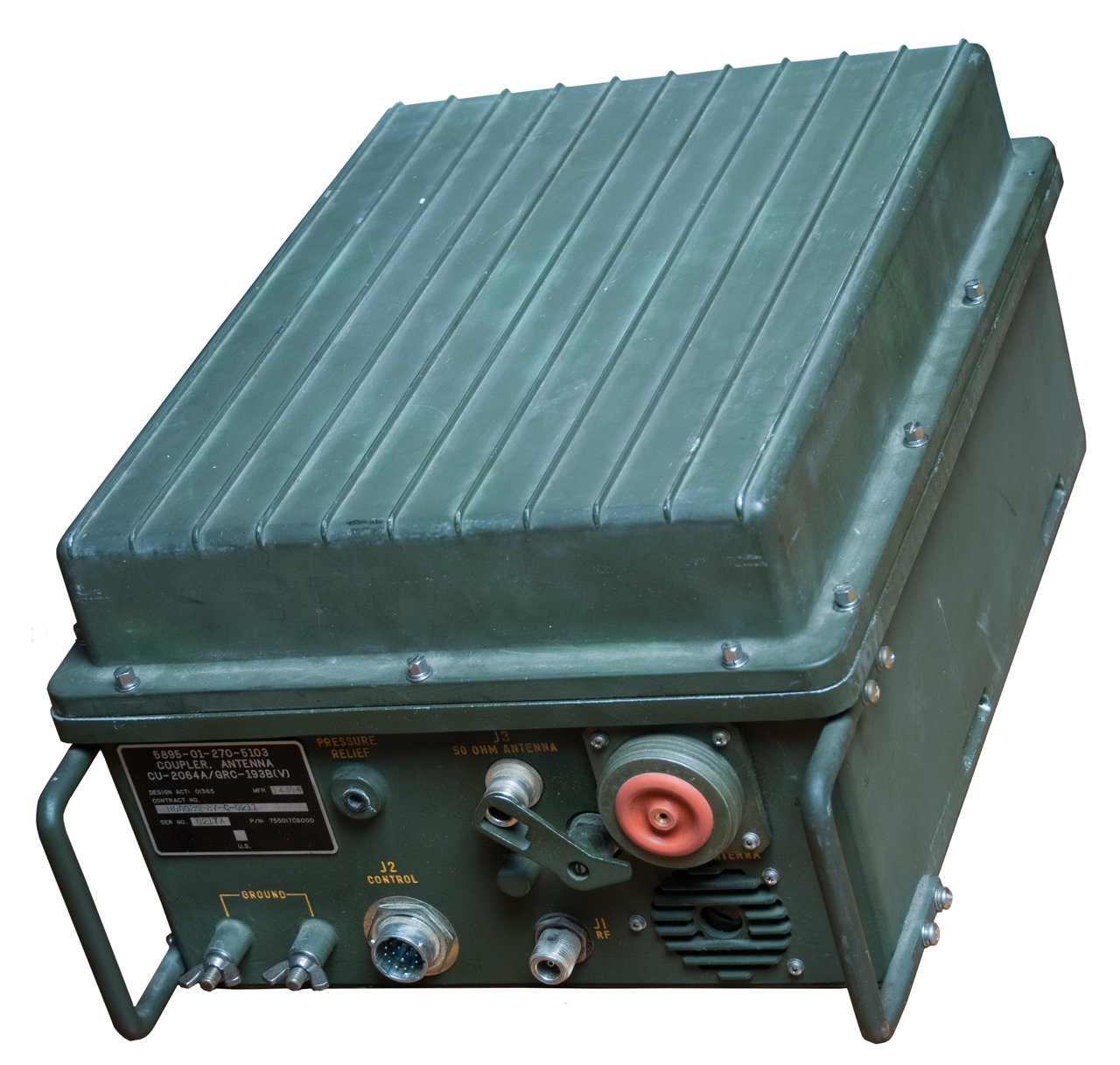
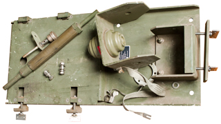
CU-2064 Antenna Coupler Harris
Motors
There may be an issue with this tuner sticking or not tuning
properly. Looking at the manuals it's clear that they have
a LUBE section.
Dave Ross said it first anThed uses it for the title of his web
page:
Real Radios Have
Motors.
So Lubing the tuner may be the first order of business since
it's sat for some decades without being used.
The RF Amp and Antenna Coupler both have 1987 contract dates and
it's now 2012 so about 25 years.
AM-6879
Audio Amplifier-RTTY Converter
Alows for Teletype, Computer or
FAX communications.
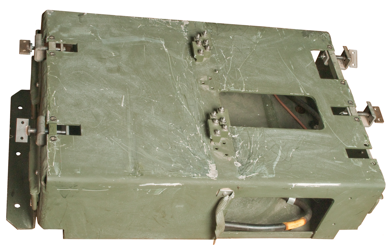
MT-6232 Army GRC-193 System Mount
MT-6233 Single Level GRC-193 System Mount
This mount is for installing the
GRC-193 into tracked vehicles like the M1113 APC.
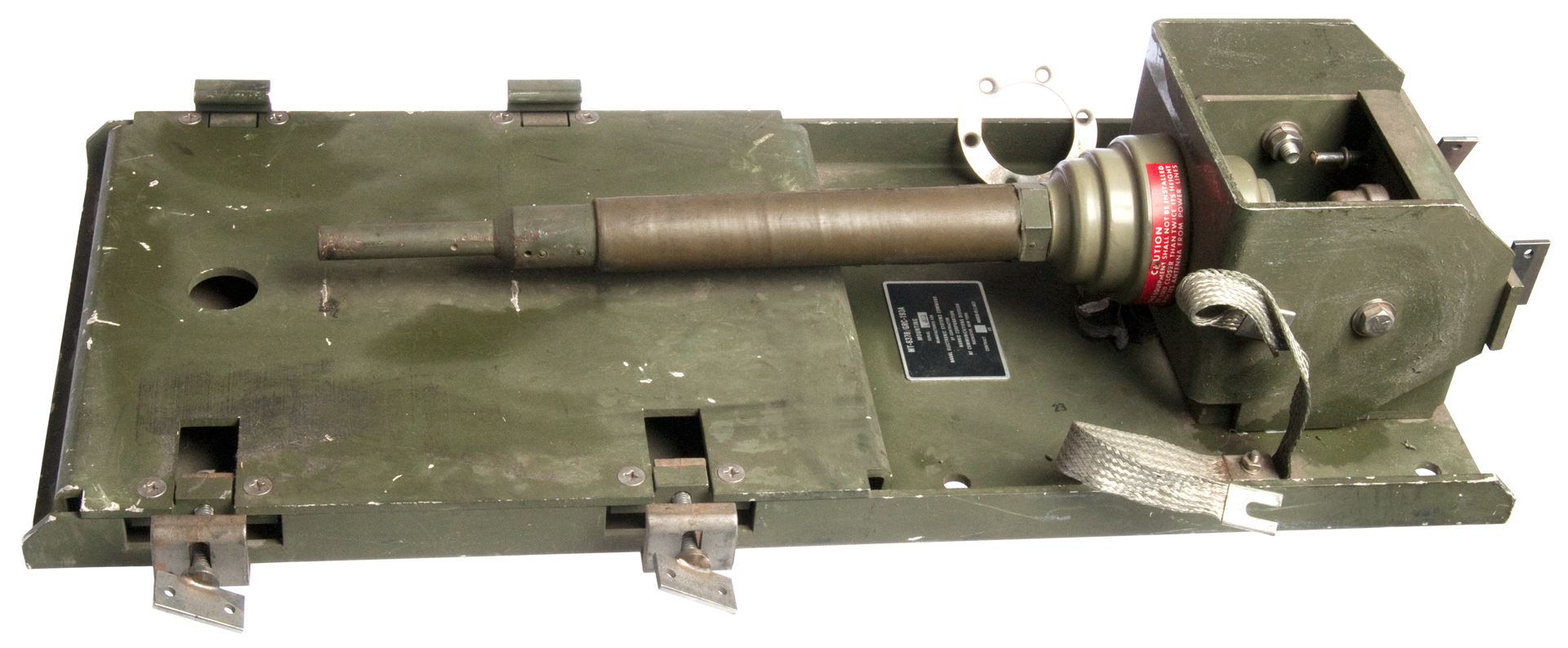
MT-6378 Mount
MT-6378/GRC-193A Mount, Remote Siting Lowered Position
This base is the AB-652.
|
What's needed to convert to the AT-1011
mast elements?
Ans: The Witch's Hat AT-1011 base.
|
This is part of the remote antenna siting kit (MK-2560) aka
Remoting Kit.
Power Supplies
Military Vehicle 24 Volts
This would be the most common
way to power the GRC-193 system.
PP-7333
TM 08077A-15 PP-7733D
PP-8474
NSN: 6130-01-475-4999
Input: 115VAC, 47 - 63 Hz
Output V: 24-28 VDC
Output I: 0 – 60 Amps
World Power Supply
Like the PP-8474 except
Input: 115/230 VAC 47 - 63 Hz
Output V: 18 - 30 VDC
Output I: 0 - 60 Amps
DC out connector: 3-pin Cannon Type MS3106F222S
Cables
Antennas
RF-4032 Tactical Antenna Siting
Kit
1. MT-6378 NSN: 5975-01-200-9797
- holds AT-1011/U or smaller diameter antanna made from AB- or
MS- mast sections.
2. Reel with Coax and Control cables (100 foot?)
WANTED
Contact - NVIS
Remote Control