Tuning Forks & Helmholtz Resonators
© Brooke Clarke 2017 - 2025
Description
Tuning Fork
Testing
Helmholtz Resonator
Vibrating Reed
Vibrating Reed Relay
Examples
Simple
Teletype Motor Speed Test
American Time Products 200 Hz
Melpar 10HDN6 Frequency Standard
Hathaway Instruments Inc. BACR20 A4
RCA Crystal Unit VC-5-M
US Army Signal Corps Frequency Meter TS-65D/FMQ-1
Accutron
General Radio Audio Oscillator
Resonance Box
Lab Demonstration Electromagnetic Tuning Fork
Electromagnets
NBS 1,000 CPS Standard
Riverbank Laboratories 60 CPS
Patents
La Cour Motor
Deagan Tuning Fork
Telechron
MEMS
Audio Frequency Shift Keying Tones
Speed of Light
Michelson
Stoll
G. Boulitte
Related
References
Links
Background
Started this after seeing the eBay listing titled: Helmholtz Sound Synthesizer (Ref 1) by Max Kohl AG (Wiki) - The Earliest Electronic Keyboard. Although I don't think the claim about being the first electronic keyboard is correct. Two key concepts that make up the Synthesizer are electromagnetically driven tuning forks (Wiki) and Helmholtz Resonators (Wiki). While working on this web page I've read in some free (very old) Google books that the Sound Synthesizer did not do a very good job of mimicking vowel sounds. It takes about twice as many sound sources to do a passable job.
The devices on this page operate mostly in the audio range, but are closely related to quartz crystals that operate at higher frequencies and with higher Quality factors (Wiki). See Related below for my web pages relating to Crystals.
Historical Note
The Ultimate 432Hz VS 440Hz | CONSPIRACY + Comparison, 12:13 - for many reasons there's nothing to this.
Description
Tuning Fork
Tuning forks have many uses such as:
- tuning musical instruments (Piano Frequencies: 27.5, 55, 110, 220, 440, 880, 1760, 3520, 261.626 Hz) (music: top octave)
- in clocks and watches (Bolova Accutron (Wiki, below, 360 Hz)
- Medicine (128 & 256 most common Powers of 2)
- Quack medicine see: Faradic Chakra
- Police Radar Gun (Wiki) calibration (Wiki: Doppler) 55 MPH: 10.525GHz=1726 Hz, 24.150GHz:=3961 Hz, 35.5GHz: =5823 Hz; fd = 2 v fo / c )
- as a gyroscope (often as a MEMS (Wiki)
- Interrupter for other circuits or source for divider or other Science (50, 60 or 400 Hz power line, Powers of 2: 64, 128, 256, 512, 1024, 2048, 4096, 32768 Hz; Teletype: 87.6, 96.19, 180 Hz)
The tuning fork is a resonator that produces a tone with less harmonics than other types such as strings. This can be further enhanced when, after striking the fork, you touch the tines near the bottom of the "Y" to damp out the higher harmonics.
Note that the tines move away from each other then move closer to each other. The stem moves axially (up and down).
In the early days of electronics (after vacuum tubes were available in the mid 1920s) electromagnetic drives were used to keep tuning forks oscillating and sense the vibrations so that they could be made to operate continuously.
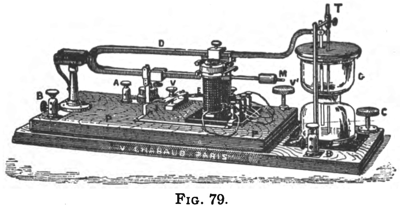
The Villard Interrupter (Ref 2) is used in the Max Kohl Synthesizer
Testing
I just happened to have some Tattoo Machine Coils on the desk as well as some magnets stuck to the table legs. By combining them with a DMM and can measure the frequency of a tuning fork that has some ferrous metal. The procedure is to place a permanent magnet on the core of the coil this way any movement of a ferrous object near the coil will generate AC electricity. Now for the Fluke 87 IV DMM:
Turn on to VAC
Press Back light (to make it easier to see the LCD)
Press Hz to measure frequency
Press Min/Max to record peak values
Press Min/Max to display the maximum value.
Strike tuning fork and hold one tine near the coil core.
Fig 1 There was a question about VPS vs. Hz.
You can see that the fork marked 87.6 VPS is actually 87.54 Hz, so in this case VPS = CPS = Hz.
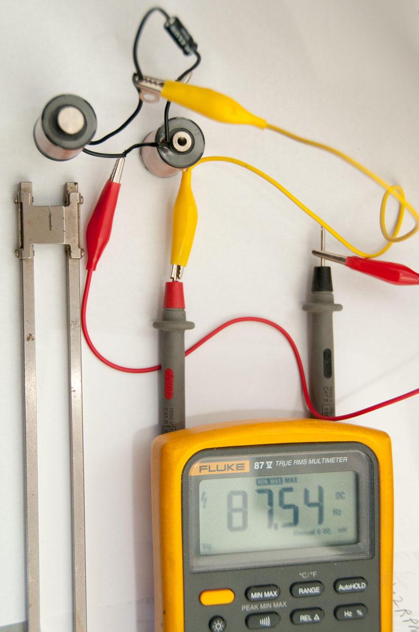
Fig 2 Fork marked 523.3 Measures 523.3. This fork has been tuned, See below.
Helmholtz Resonator
Hermann von Helmholtz (Wiki) was a pioneer in many areas. Also see my Helmholtz coil information.
Note that the Helmholtz Resonator (Wiki) is much smaller than a 1/4 wavelength tube type resonator. A common example is a beer or soft drink bottle.
Vibrating Reed
A vibrating reed might be thought of as half a tuning fork. It's a very simple device. For example a wire or sheet metal strip made from a material with some elasticity will vibrate at it's natural frequency when plucked. Changing the length will change the frequency. The harmonica (Wiki) is an example of multiple vibrating reeds.
The electromagnetic drive circuit for buzzers and bells may have a natural resonant frequency with low Q so that it can be pulled up or down some, but not a lot?
A vibrating reed device is probably only slightly less accurate than a tuning fork, but is a lot less expensive, so they find applications that are cost sensitive.
2779920 Audio frequency meter, Petroff Merlin, 1957-01-29,
Vibrating Reed Relay
A relay that only operates when the AC drive signal is at a specific frequency. Commonly used for remote controls, or early pagers.
2795672 Frequency selective vibrating reed relay, Arthur H Maciszewski, Goldstein Richard, ARF Products, 1957-06-11, -
Examples
Simple
These are tuning forks that need to be manually tapped to get them going.
Fig 1 Set of Tuning Forks
Fig 2 64 Hz Weighted "C" Tuning Fork
Note the Allen screws that hold the weights in place are steel.
They can be sensed by the combination of an electromagnet, permanent magnet and DMM.
Fig 3 320 Hz generic Aluminum
Came with the Resonator Boxes (see below)
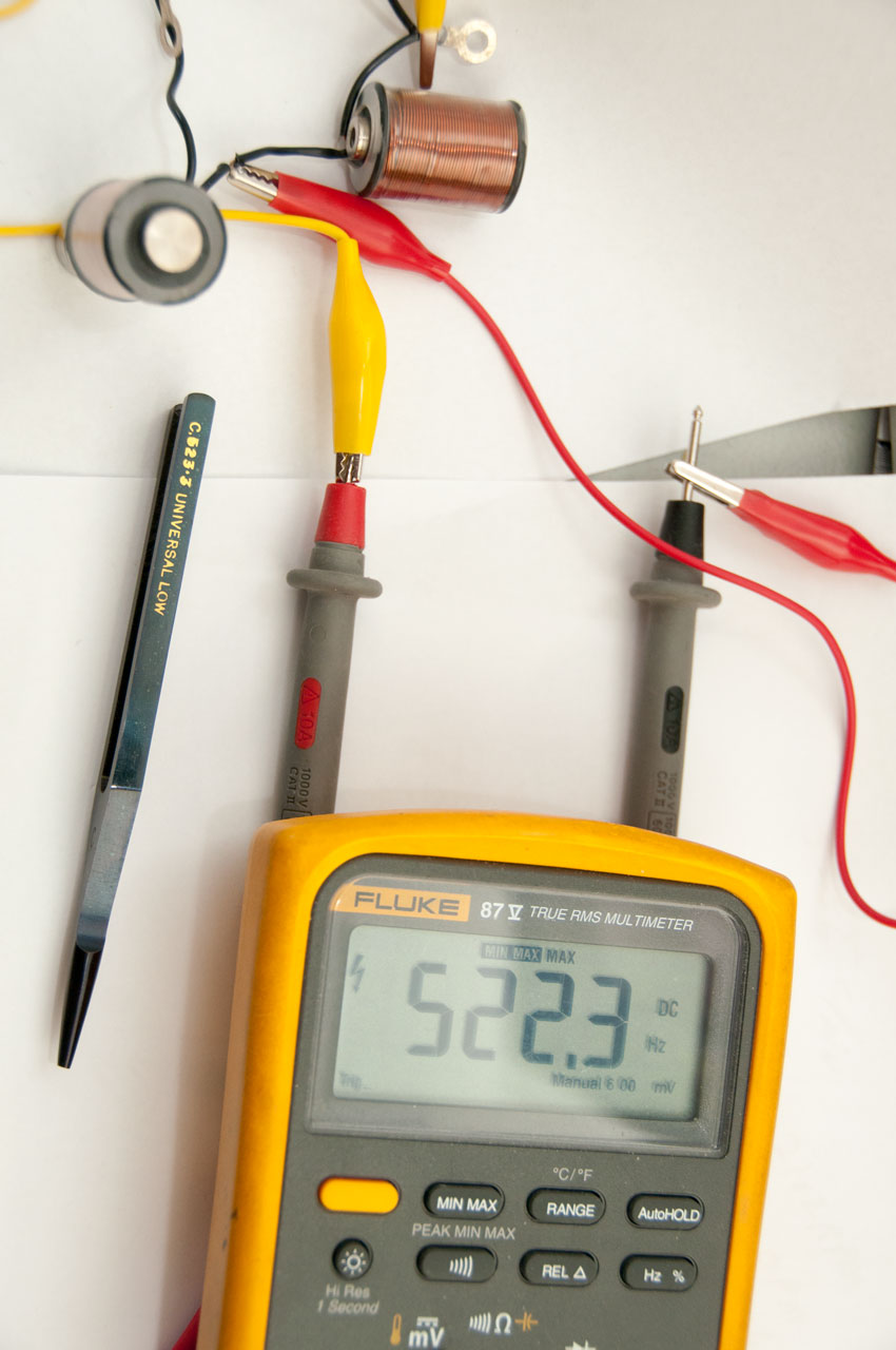
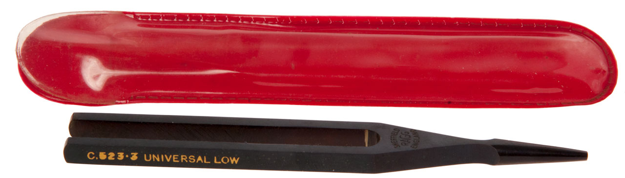
Fig 4 Sheffield Ragg England C.523.3 Universal Low
Notice tuning mark at the base of the tine at at the joint with the yoke.
There's another tuning mark on the other tine. The base of the stem is a round cone.
Very nice.

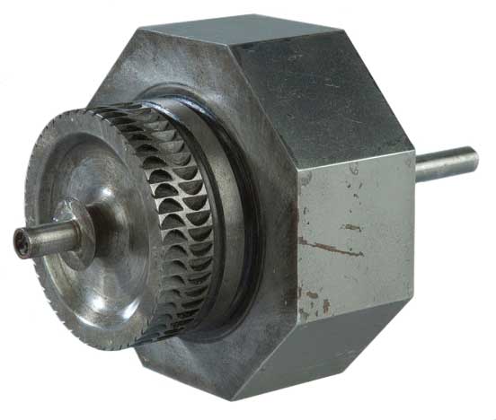
Teletype Motor Speed Test
VPS = Vibrations Per Second, which in clock circles is half a cycle. But that does not apply here.
87.6 V/sec * 60 sec/min = 5256 Vibrations/minute. See Testing above.
Note there is a slit in each vane and the pair of vanes act as a shutter to provide a stroboscopic effect when looking at gear wheels.
Used to adjust motor speed in Teletype (Wiki) equipment.
87.6 VPS
When tested on an Android using audio spectrum analyzer apps the peak is:
177.65 Hz or 86.1 Hz.
TM 11-2222 says motor: 2102 RPM and 368.1 Operations Per Minute
96.19 VPS fork for 2308 RPM & 404 OPM
180 Hz NSN: 5815-00-224-9717
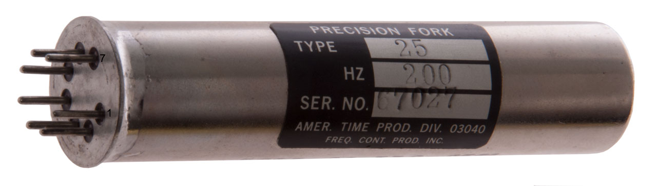
American Time Products 200 Hz
The 7-pin base matches a 7-pin tube socket.
Marking:
NSN: 5825-00-736-8521
Resonator, Tuning FO
9LA900-85-M-8204
date Code: 8517
03040
Pin Out: Pins 1 & 4 = 468 Ohms, Pins 6 & 7 = 950 Ohms
It's not clear which is the drive and which is the sense winding, but it's likely that the higher resistance coil is for sense.
1
2
3
4
5
6
7
1
-
OL
OL
468
OL
OL
OL
2
-
-
OL OL OL OL OL 3
-
-
-
OL OL OL OL 4
-
-
-
-
OL OL OL 5
-
-
-
-
-
OL OL 6
-
-
-
-
-
-
950
7
-
-
-
-
-
-
-
Melpar 10HDN6 Frequency Standard 60 cps
I remember the defense contractor Melpar (Wiki) when I was working (1960 - 1990).
Top marked:
Model
10HDN6
Freq. CPS
60
Tolerance +/- .1%
Temp deg C
+65
0
Frequency
Standard
Patent No.
3106124MELPAR
[logo]
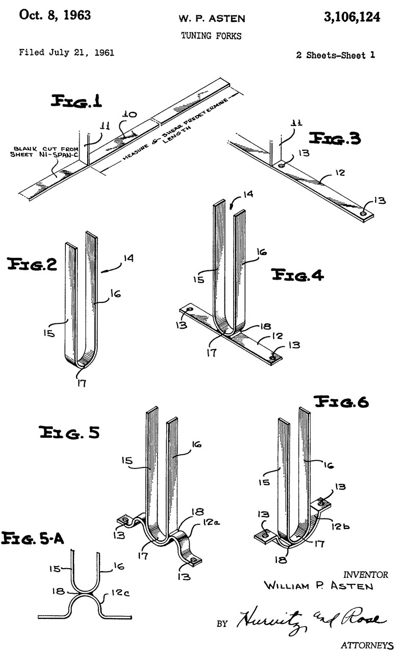
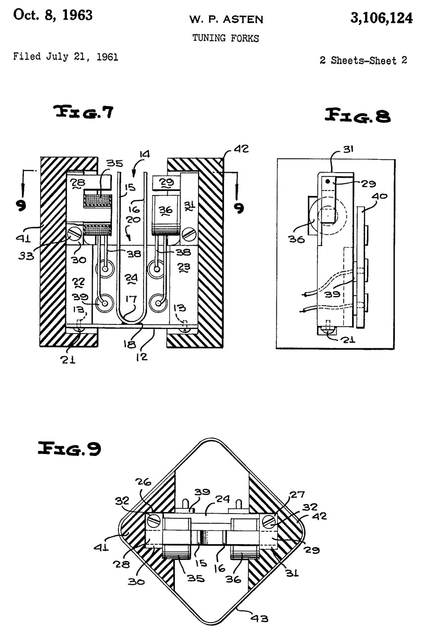
Fig 1 see patent 3106124 below
Fig 2
This is a hermetically sealed 60 Hz frequency standard based on a tuning fork design.
Operation
With +5 VDC input with the can pressed to your ear you can hear the tuning fork at a pitch much higher than 60 Hz. With +15VDC input the output is about 5.0 VAC at 60.00 Hz as measured on a DMM.
3106124 Tuning forks, William P Asten, Melpar Inc, Oct 8, 1963, 84/457, 984/260, 310/25, 84/409, 116/DIG.300 -
The patent covers the sheet metal tuning fork and how it's packaged, but not the oscillation circuit.
The main idea is to use sheet metal stamping instead of machining to make the fork itself.
After abrading each tine so it's frequency is slightly below the desired frequency the can is sealed in a chamber with adjustable pressure.
The fork frequency is measured and as the pressure goes down the frequency goes up and can is sealed at that pressure where the fork is at the desired frequency.
The fork and it's mount is made from NI-SPAN-C (tm International Nickel Corp). Curie point 160 deg C and a negative temp coefficient of elasticity. By proper heat treating the zero temp coefficient of elasticity can be made to occur at 15 deg C and is positive on either side of that temperature.
2874602 Apparatus for maintaining constant the vibration frequency of a tuning fork, Asten William P, (not assigned), Feb 24, 1959, 84/409 - This drive circuit was designed add temperature compensation to a NI-SPAN-C sheet metal tuning fork, i.e. it matches the above patent.
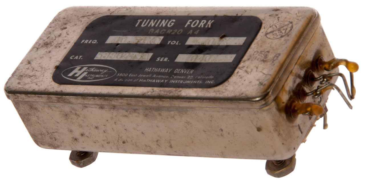
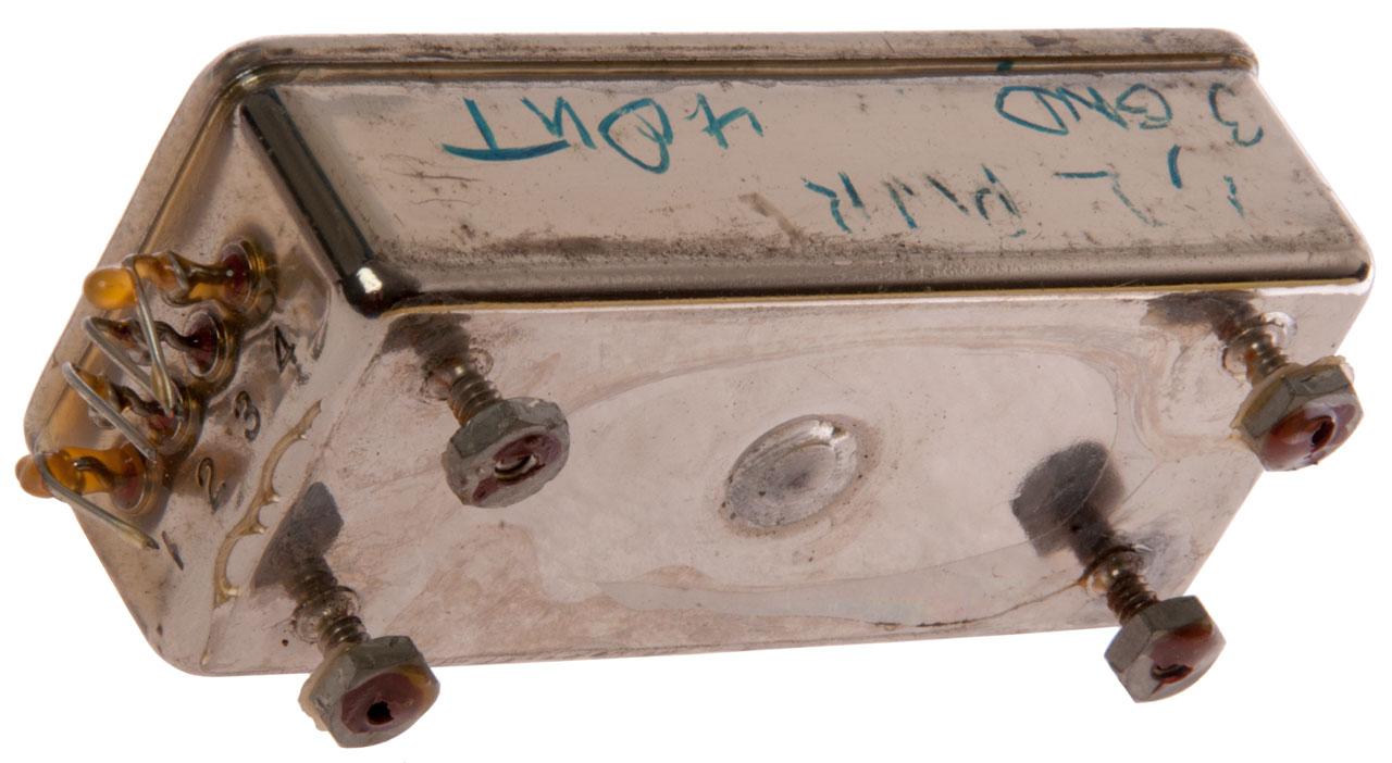
Hathaway Instruments Inc. BACR20 A4 Tuning Fork
This is similar to the Melpar Tuning Fork frequency standard above except the output frequency is 10.51 kc. To me this seems like a strange frequency.
Label:
Tuning Fork
Freq. 10.51 KC Tol. +.01%
Cat. 58802-3A Ser. 040
Hathaway Instruments Inc., Hathaway Denver
5800 East Jewell Avenue, Denver 22, Colorado
A Division of Hataway Instruments Inc.
Dec 6, 1961
{inspection stamp B2/337
Fig 1
Fig 2 Hand written:
1, 2 - Pwr
3 Gnd 4 Out
Pins stamped 1 to 5 left to right
2687338 Synchronous time system for oscillographs, Davis William L, Hathaway Instr Company, Aug 24, 1954, 46/107.4, 250/208.4, 324/88, 318/85 - Tuning fork ((a & 9B) based. makes time marks on paper or film oscillographs.
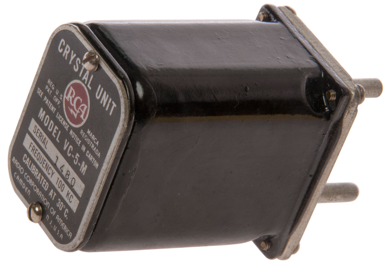
RCA Crystal Unit VC-5-M
This is a quartz crystal, but from the same 1960s time frame as these tuning fork oscillators.
This may be a CR-15/U, CR-16/U, CR-29/U and/or CR-30/U Crystal Unit (Ref 5) also it uses the HC-5 Crystal Holder.
Label:
Crystal Unit
Pat Off.
RCA
Registrada
See Patent License Notice on Carton
MODEL VC-5-M
Serial 1480
Frequency 100 KC
Calibrated at 30 (deg) C
Radio Corporation of America
Camden N.J. U.S.A.Stamped on side:
M-254141-1
[A5]
Inspection stamp SC/831P
On Bottom:
red box [TEST 17]
67
79
Maybe tested in 1967 and retested in 1979?
Fig 1 There is a rubber gasket between the bottom
and the black case.
Fig 2 Two bottom pins are ground.
2326923 Art of mounting piezoelectric crystals, Bokovoy Samuel A, Rca Corp, Filed: Sep 30, 1941, Pub: Aug 17, 1943, 310/354, 310/344 -
3073975Crystal Unit, Robert R Bigler, Edward M Washburn, Rca Corp, Jan 15, 1963, 310/344, 310/348 -
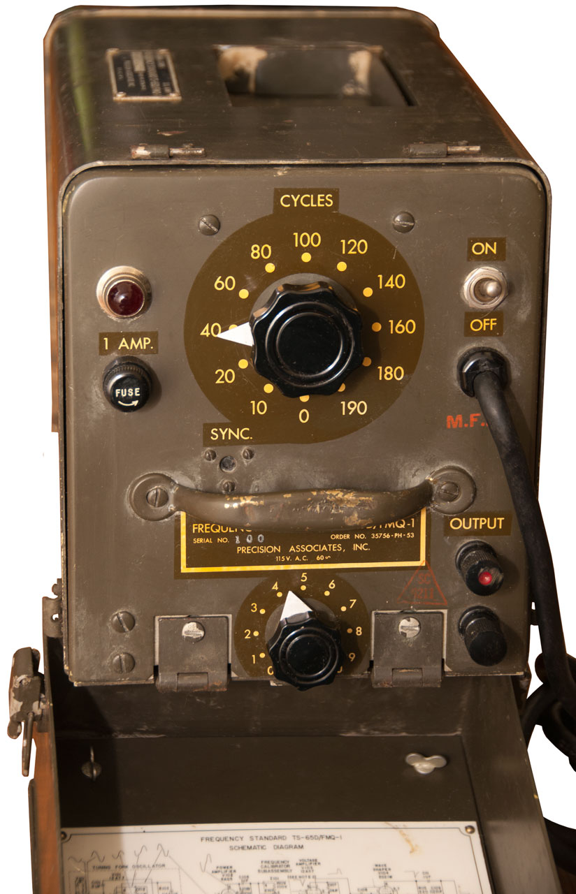
US Army Signal Corps Frequency Meter TS-65D/FMQ-1
This is a test set to calibrate the TMQ-5 Radiosonde receiver. Inside there is a white powder like coating on some of the parts. Maybe this unit was in a fire where a dry chemical extinguisher was used?
Manual TM 11-6625-407-14 Operator's, Organizational, Direct Support, and General Support Maintenance Manual,
Frequency Standard TS-65C/FMQ-1 and TS-65D/FMQ-1
(NSN 6625-00-649-4279)
Headquarters Department of the Army
October 1973
Label:
Signal Corps U.S. Army
Frequency Standard TS-65D/FMQ-1
Serial No. X100 Order No. 35756-PH-53
Precision Associates Inc.
115 VAC 60~
Photos
Fig 1 Handle up.
Fig 2 The lid can be separated from the main chassis. The line cord is permanently attached.
Fig 3 Top knob is mechanical radius selection for the lamp-photocell, i.e. frequency.
Lower knob is output level.
Fig 4 Schematic.
Fig 5 Inside Top
To open remove 2 screws on rear panel,
Loosen 2 Dzus (Wiki) fasteners on front panel.
Use handle on front panel to lift chassis out of case.
Tall round can at right center marked:
64153
543
60
and is the 60 CPS tuning fork.
Fig 6 Inside Bottom
Note long "tail" from tuning fork that is bent over. What's up with this?
Fig 7 The Block at top contains a pilot lamp and photocell and moves up and down. Shown almost all the way up.
Fig 8 gold color 60 CPS motor at right just behind front panel. White stuff on wheel.
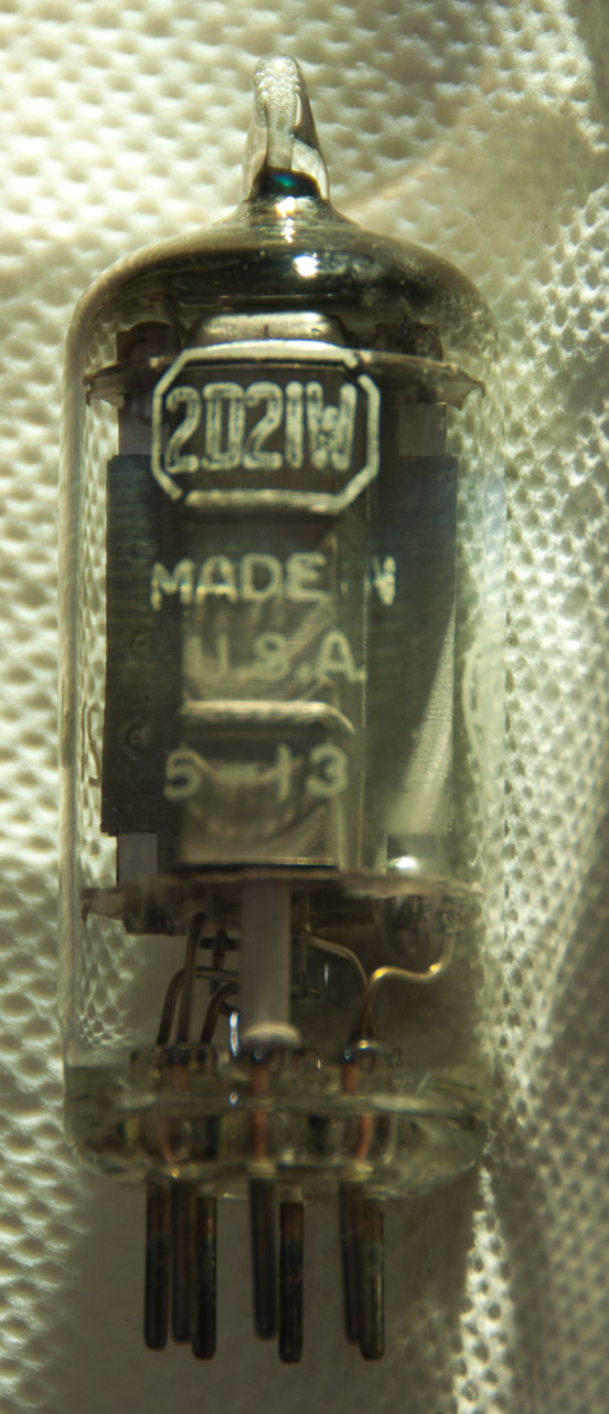
Fig 9 2D21W Thyratron (Wiki)
Used extensively in W.W.II.
Torpedoes, VT Fuses,
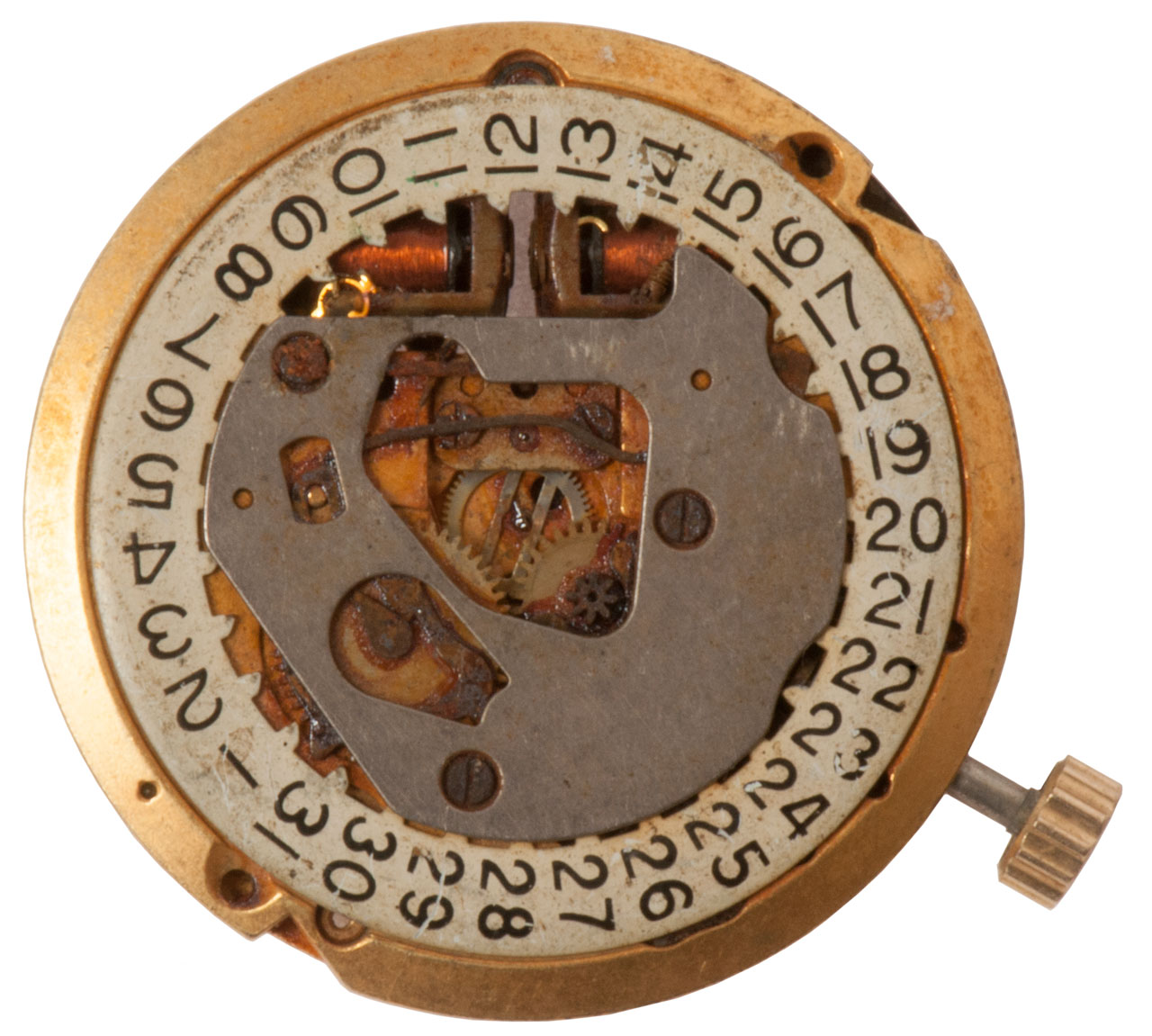
Bolova Accutron Tuning Fork Watch
Bulova (Wiki) invented a watch where the time keeping mechanism was a tuning fork rather than a classic balance wheel (Wiki). It was more accurate that balance wheel watches. See Ref 10 (1800 Mechanical Movements, Devices and Appliances by Gardner D. Hiscox, 1921: Device No. 1006 page 260: Intermittent Rotary Motion.)
This watch was left on a workbench loose and has picked up many many small ferrous metal parts. It also has some kind of goop that needs to be cleaned. Maybe Naphtha in the Ultrasonic Cleaner?
The tines do move, but they don't cause the gears to turn.
Fig 1 at the top: "Pat. 2971323 Et Al"
U.S.A.
Bulova
218D
There is a small screw and piece of wire to the left of the left coil held by the magnetic field.
Fig 2 You can see a small circlip at "9" held in place by the magnetic drum of the left tine.
Patents
2782627 Device for measuring the amplitude of the vibrations of a watch escapement, Max Hetzel, Bulova Watch Co Inc, Filed: May 19, 1952, Pub: Feb 26, 1957, 73/1.48, 968/771 -for testing balance wheel watches.
Max Hetzel also patented a number of devices for adjusting balance wheels and these included electromagnets (2707875, 2714306, 2748595).
This version only shows one electromagnet.
2949727 Electric timepiece, Max Hetzel, Bulova Watch Co Inc, Filed: Jun 19, 1953, Pub: Aug 23, 1960, 368/157, 984/260, 310/15, 368/167, 968/486, 968/482, 968/483, 84/457, 968/481 -
Cites WE patent 1560056 (an early electromagnet driven tuning fork, see below)
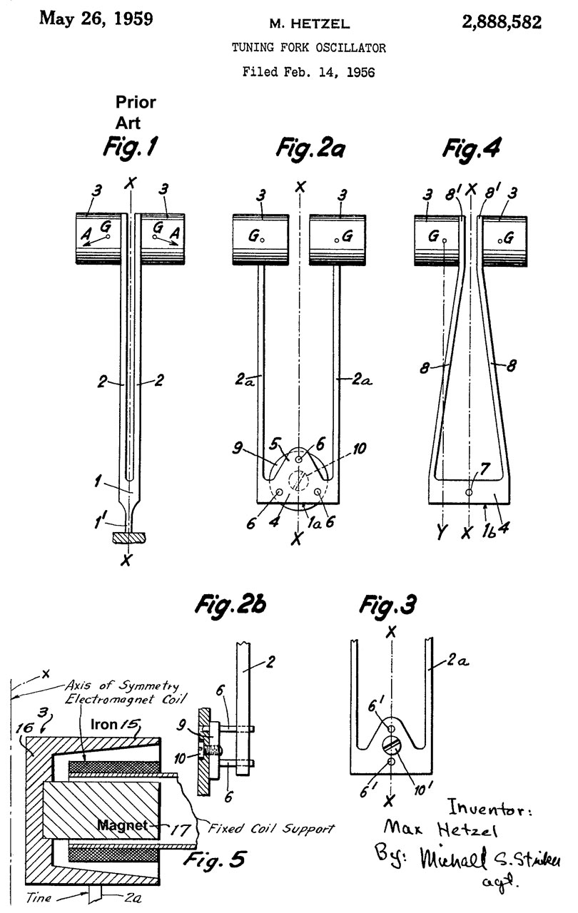
2888582 Tuning fork oscillator, Max Hetzel, Bulova Watch Co Inc, Filed: Jun 19, 1953, Pub: May 26, 1959, 310/25, 968/481, 984/260, 968/482, 968/483, 84/409, 968/486 -
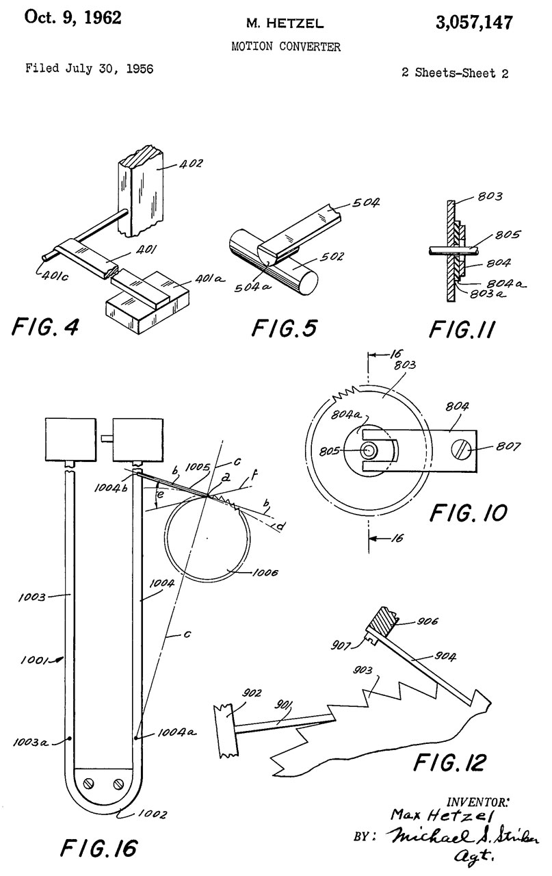
2908174 Motion transformer, Max Hetzel, Bulova Watch Co Inc, Filed: Oct 23, 1953, Pub: Oct 13, 1959, 74/128, 74/160, 968/79, 368/125, 74/578, 368/135, 74/144, 968/482 -
This is about how to transform the vibratory motion of the tuning fork into rotary motion for the gear train.
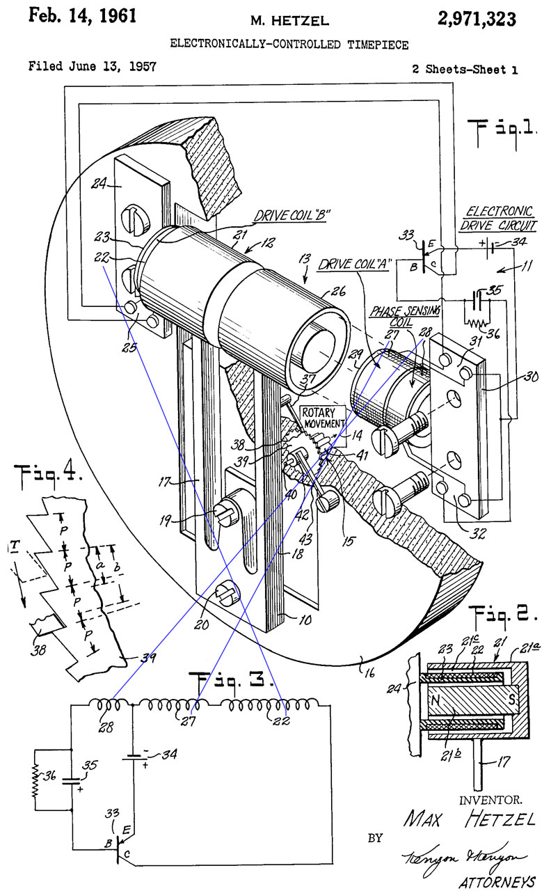
2971323 Electronically-controlled timepiece, Max Hetzel, Bulova Watch Co Inc, Filed: Jun 19, 1953, Pub: Feb 14, 1961, 368/157, 74/142, 310/25, 968/481, 318/130, 331/156, 968/486, 331/116.00M, 968/482, 984/260, 968/483 -
2929196 Electric timepiece, Max Hetzel, Bulova Watch Co Inc, Filed: Mar 12, 1956, Pub: Mar 22, 1960, 368/167, 968/482, 310/27, 318/132, 968/486
This is a dual electromagnet design where the left coil is in the collector circuit and the right coil is in the base circuit.
206 is described as a permanent magnet.
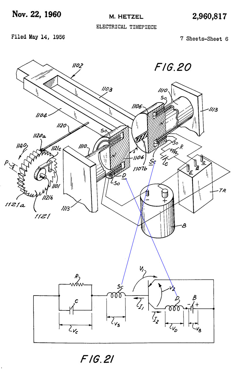
2960817 Electrical timepiece, Max Hetzel, Bulova Watch Co Inc, Filed: May 12, 1955, Pub: Nov 22, 1960, 368/125, 310/25, 968/486, 74/142, 331/116.00M, 331/156, 968/482, 968/481, 318/132, 368/167, 318/128, 968/487 -
1106: Cup shaped permanent magnets (South pole) and a central rod (North pole) part of tuning fork.
Sc: Sensing Coil
D: Driving Coil
B: 1.3 Volt Mercury coin cell Battery
TR: Germanium Transistor The characteristics of the transistor stabilize the drive current
C: 2 uF Capacitor
R: 2 Meg Ohm Resistor
3057147 Motion converter, Max Hetzel, Bulova Watch Co Inc, Filed: Jul 30, 1956, Pub: Oct 9, 1962, 368/125, 310/21, 368/167, 74/126, 310/25, 968/482, 968/481 - how to get vibrations from tuning fork into gear train.
3070951 Frequency-adjustable tuning fork type vibrator for an electrically energized timepiece, Max Hetzel, Bulova Watch Co Inc, Jan 1, 1963, 368/167, 84/409, 331/156, 84/457, 968/486, 368/200 - adjust tuning fork frequency to extremely close limits. done by adding a wire that can be bent to tune the frequency.


General Radio 1000 CPS Audio Oscillator 213B
The 831-A and 213B are both 1000 Hz tuning fork oscillators. The 213 runs on 6 VDC.
The manual for the 831-A says 4.5 VDC for normal operation, but for increased output voltage and higher harmonics you can use up to 8 VDC. A circuit modification to add a resistor in series with the output microphone to lower it's current might be required to minimize microphone carbon granule packing.
The 213-B runs at 1000 Hz (common audio test frequency and used for oscillograph timing marks) and the 213-C runs at 400 Hz (aircraft AC mains frequency)
Description
The coil on the lower tine generates a field to cause the tine to be magnetized. The "U" shaped transformer core at the tips of the tines applies the drive signal. The chrome plated dome above the fork is a carbon microphone element that senses the tine movement. The fork is marked 1000 ~.
As received it's not operational. After removing the chrome metal microphone cover it was seen that the spring was not making contact with the carbon element. By slightly stretching the spring it was wiggled onto the mike element.
The black tape that's wrapped around the drive electromagnet is loose and touching the bottom of both fork tines adding friction. Maybe enough to keep it from running?
Fig 1
Fig 2
Fig 3 Carbon microphone Spring inside chrome metal cover.
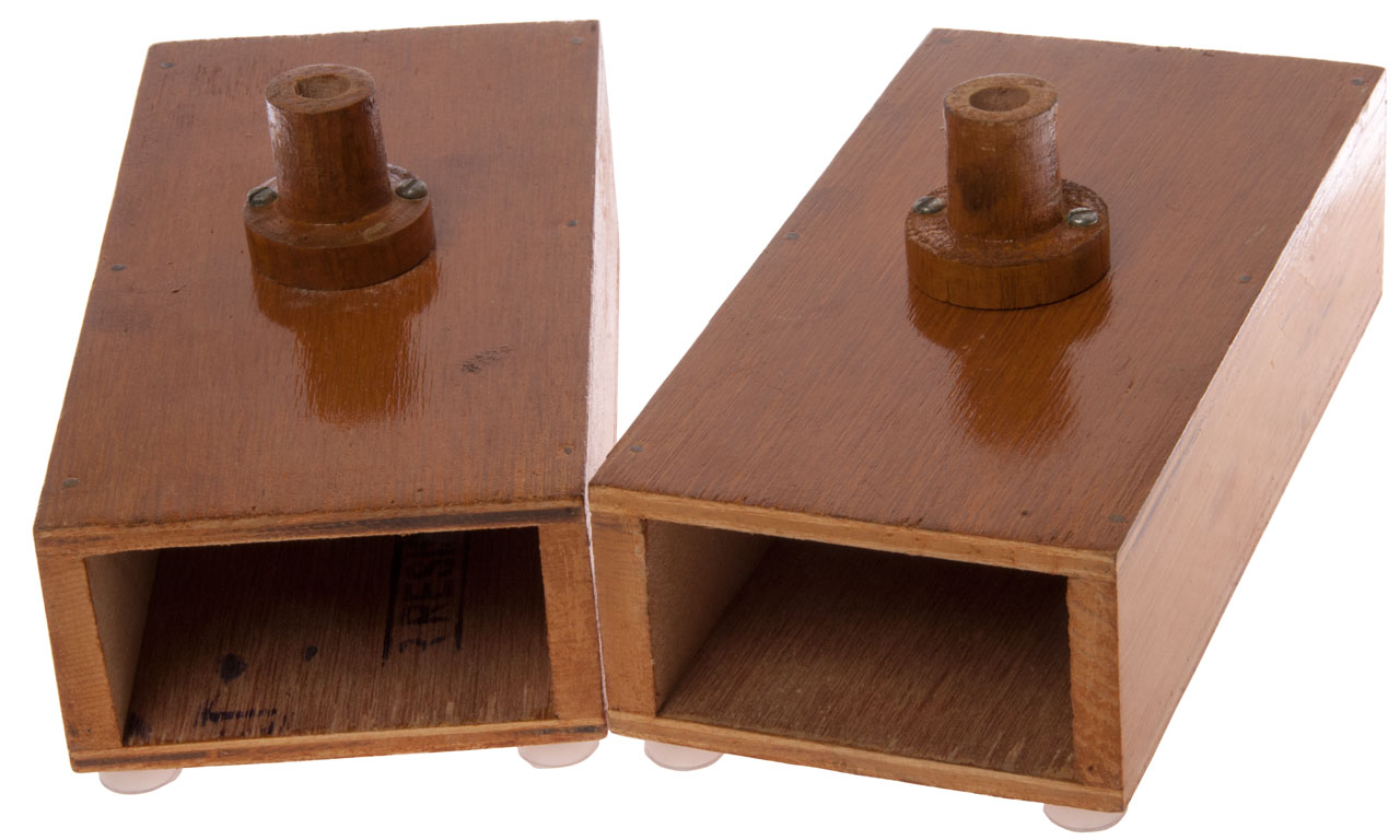
Resonance Box
This is a classical physics experiment. But . . . I don't think the correct tuning fork was included. The two boxes do not couple.
These boxes came with a couple of modern 320 Hz aluminum tuning forks with rectangular stems that are too big to fit into the hole in the spools.
The interior dimensions are:
73mm wide x 38.5mm high x 173 mm deep
The box is probably just a 1/4 wave resonator so the depth is given by (velocity of sound) / (4 * frequency). So. frequency of these boxes is:
F = 340 meters/second / (4 * 0.173 meters) = 491 Hz. (This is neither a power of 2 or a Chakra frequency. Not sure what this frequency is used for?
Maybe these would work with 440 Hz forks?
For 320 Hz the quarter wave length is 0.2656 meters (10.457")
This can be confirmed by striking the 320 Hz tuning fork and holding it near the open end of a paper towel roll where the other end is blocked. Inserting a dental floss box into the closed end a little improves the resonance since the paper towel roll is 11" long and the desired length is about 10 - 1/2".
Also the location of the fork support seems questionable, maybe it should be centered on the width, like it is now, but with the center of the stem at the open edge?
Fig 1


Electromagnets
See the Magnets web page for the Tattoo Machine Coil electromagnets.
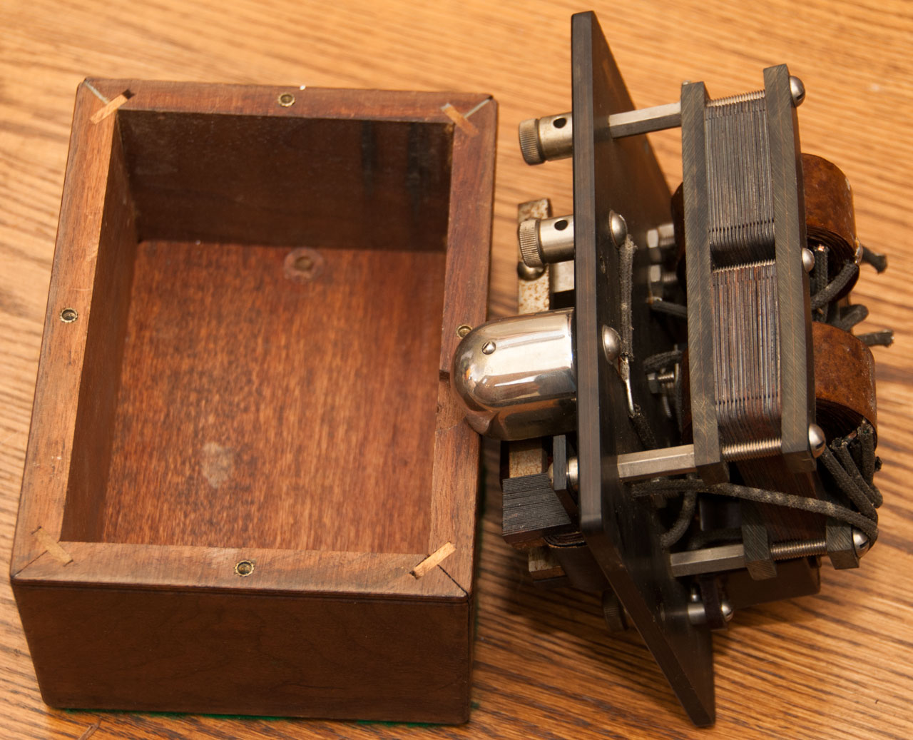
Lab Demonstration Electromagnetic Tuning Fork -
This probably was used as a demonstration in Physics lectures and probably fits chemistry/physics lab stand clamps.
There are 4 contact points on the fork and the opposing adjustable contact can be moved to any of them.
DOA
The electromagnet is not working, it's shorted. Tests:
1. Connected to a lab DC power supply and with .25 Amps flowing the voltage drop is small and there is no magnetic attraction.
2. Using theFly Back Testershows a shorted turn.
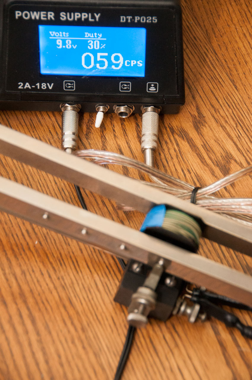
3. Unwrapped wire and found no problems. Wire dia = 0.036 i.e. 19 AWG and the length for 0.2 Ohms is about 25 feet which looks correct. So it just needs a lot of current. Connected to the HP 6038A power supply set for 9 Amps max and the fork ran, but sparks between the tine nearest the contact and the metal coil frame.
Turning down the voltage the fork runs on about 3 Volts and about 2 Amps (average). When connected to a Tattoo power supply with frequency readout it shows 59 or 60 Hz (see Fig 5). So the reading of 387.6 Hz on the smart phone app was actually a 6.5 times harmonic (seems strange for the half part of that, but that may just be a problem with the smart phone spectrum analyzer app and or poor microphone sensitivity at 60 Hz.
Fig 1
Fig 2 The overall length is 17". The tines are about 13-1/4" long and 3/4" x 3/8"
Using an audio spectrum analyzer on my Android phone the frequency is 387.6 Hz.
This is not a musical note on the equally tempered scale. False reading since cell microphone is not sensitive to 59 Hz
Fig 3 The rods are all 1/2" diameter.
Fig 4 Using theFly Back Testershows a shorted turn.Is really OK.
Fig 5 Using a tattoo power supply it's easy to see the actual frequency.
YouTube Video: https://youtu.be/BdmS8Ny88b0


NBS 1,000 CPS Standard
Photo first seen on the Wiki page "In clocks and watches" paragraph.
In the 1927 NBS Yearbook on page 40 is described a 1,000 frequency standard that was adjusted using a Shortt pendulum clock (Wiki). Appears to be a one tube box very similar to the GR 213.
Fig 16 (pdf pg 408) "Pendulum oscillations" and Fig 17 "Tuning-fork vibration".
This came about because of a question about the frequencies for radio teletype, see AFSK below.
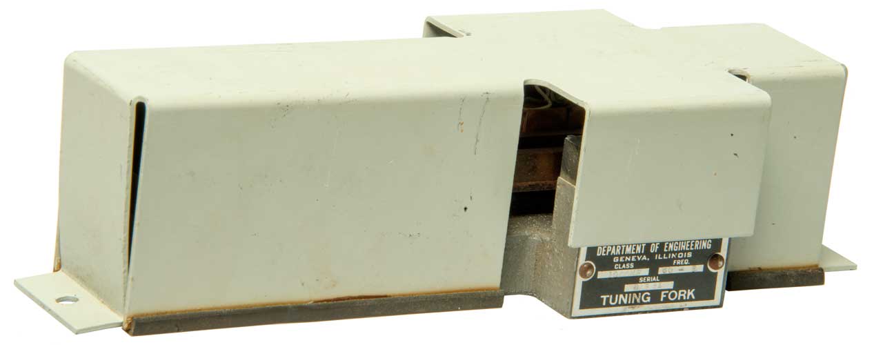
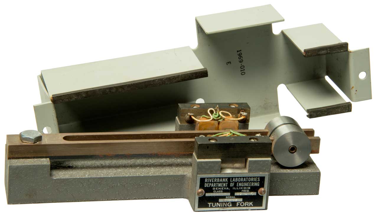
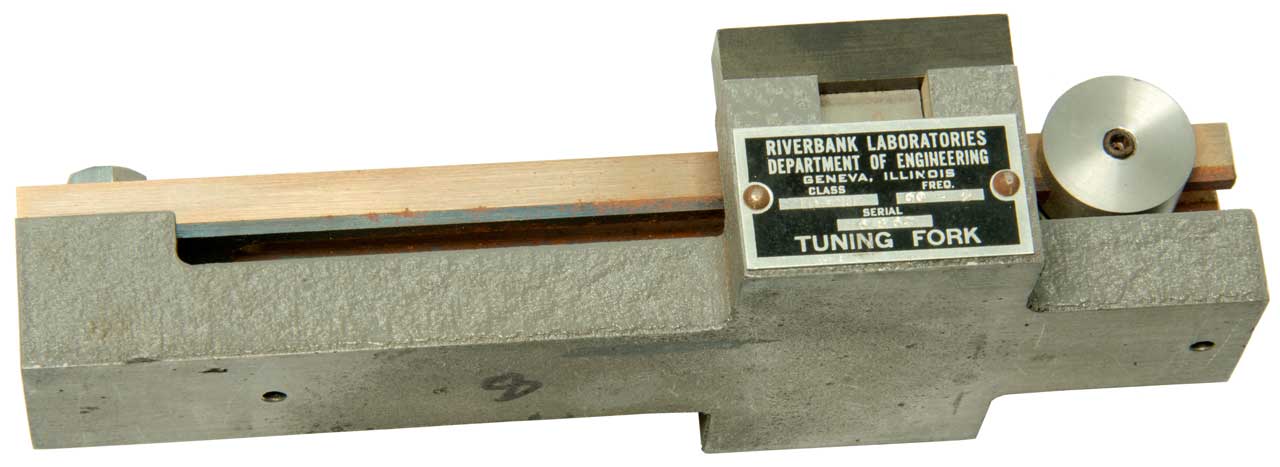
Riverbank Laboratories 60 CPS
I know the name Riverbank Laboratories (Wiki) since I have many books they printed in relation to Cryptography (Wiki) mostly reprinted by Aegean Park Press (Wiki, archive). A half interest in the patent for this tuning fork was assigned to George Fabyan (Wiki) who was a millionaire business man who funded Riverbank Labs.
Label:
This is a 60 CPS tuning fork driven by a couple of electromagnetic coils and there are not any mechanical switch contacts, like on the Lab Demonstration tuning fork above.
Department of Engineering
Geneva, Illinois
Class Freq.
1000MF 60-5
Serial
6 B 62
Tuning Fork
There is an aluminum sheet metal cover and the base is machined aluminum with gray wrinkle paint.
The label mentions Class: 1000 MF, which may be the size of a resonating capacitor (one thousand micro Farads) to be used in an oscillation circuit?
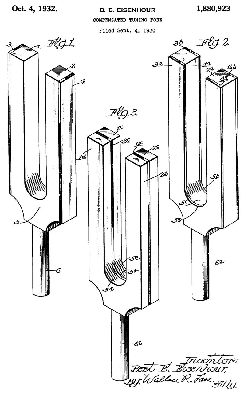
At the base of the tuning fork is stamped: B. E. Eisenhour which turns out to be the name of the inventor.
Application
Note the patent date is 1932 so the number (1969-010 E) stamped inside the cover is probably not a date.
I'm guessing that this was for driving the selector motor on a teletype orcryptographic machinewhere land based 60 cps AC power was not available, like on a ship orsubmarine.Since there were no TTY machines on ships until near the end of W.W.II it's a mystery what this was for. Let me know.
Fig 1
Fig 2
Fig 3
Fig 4
1880923 Compensated tuning fork, Bert E Eisenhour, half to George Fabyan (Wiki), 1932-10-04, 84/457; 984/260 - This is a bi-metal temperature compensation scheme not unlike what was being done on pendulum clocks.
Ad in World Tele-Tech April 1953 pg 143 - "The universal standard for frequency control...Eisenhour temperature compensated bi-metallic tuning forks are the acknowledged finest and most accurate controls on earth. Frequency ranges available from 50 cps through 10kc, tuned to +/-0.0015% as standard procedure. These champions of accuracy have temperature coefficient stability as high as one part per million per degree centigrade.
Other Bert E Eisenhour patents
1924091 Sound meter, Bert E Eisenhour, half to George Fabyan, 1933-08-29, 73/646; 73/729.1 - Sound Pressure Meter (see: GR Sound)
1830790 Electrical adapter device, Greaves Valentine Ford, Bert E Eisenhour, United Reporoducers Corp, 1931-11-10, 439/651; 324/74 - allows using radio as phonograph amplifier without removing a tube. Fits between tube base and radio socket.
2384823 Torsional oscillator, Bert E Eisenhour, half to Riverbank Labs, App:1943-02-08, W.W.II, Pub: 1945-09-18, 84/457; 984/260 - Ref patent 1880923: "Once such a fork has been made to have a fundamental frequency, it remains with it, and when it is desired to use a fork with another given fundamental frequency of vibration, it has been found more practical to construct another fork for such purpose than to make adjustments in a fork already produced for some already given fundamental frequency, as by changing the proportions of the laminations used in making up the previously produced fork."
1781376 Electrodynamic sound recorder and reproducer, Bert E Eisenhour, United Reporoducers Corp, 1930-11-11, 369/147 - for phonograph
Patents assigned to millionaire businessman George Fabyan
1390027 Means for classifying biformed alphabet, Fabyan George, 1921-09-06, 33/1R; 33/1BB - probably aimed at showing Francis Bacon wrote Shakespeare's plays which his lab later showed was not the case.
1597476 Apparatus for distilling and cracking crude petroleum and distillate, Carl M Page, Fabyan George, 1926-08-24,
1494125 Electrically-heated oil-cracking apparatus, Carl M Page, Fabyan George, 1924-05-13,
1598618 Apparatus for cracking oil, Carl M Page, Fabyan George, 1926-09-07, -
1450110 High-frequency ignition system, Carl M Page, Fabyan George, 1923-03-27, - to increase the frequency of oscillation of spark ignition (before Kettering system).
1486650 Horn for sound instruments, Arthur L. Foley, George Fabyan, 1924-03-11, -
1619468 Color mixer, Gruender Hubert, George Fabyan, 1927-03-01, for combining Red, Green & Blue light in varying amounts
1710049 Therapeutic apparatus, Fabyan George, 1929-04-23, - Quack medical: connect battery between head and feet.

Patents
A number of the early patents reference telegraph multiplex patents because they used tuning forks and/or stepping motors.
Classes
33 Oscillators
73 Measuring & Testing
84 Music
310 Electrical Generator
318 Electricity Motive Power Systems
324 Electricity: Measuring & Testing
331 Oscillators
335 Electricity: Magnetically Operated Switches, Magnets, and Electromagnets
368 Horology: Time Measuring Systems or Devices
370 Multiplex Communications
984 Musical Instruments
Patents
281339 Multiplex telegraph, Edward A. Calahan, The Standard Electric Manufacturing company, Jul 17, 1883, 370/304; 178/75 - Uses tuning fork to pack selector rotation
329090 Tuning Fork, D.W. Segrove, Oct. 27, 1885 - includes bridge slider to change frequency and musical scale markings. - there is another type of adjustable T.F. where weights on the tip of the tines are moved. These sell for under $30 whereas the shunt near the base of the fork type sell for about 9X more.
375654 Tuning Fork, D.W. Segrove, Dec 27, 1887 - starts with the 329090 fork and adds adjustable weights to the end of the tines so that the pitch of different countries can be set while still having the bridge slider calibration in tact.
395556 Vibratory multiplex telegraphy, S.D. Field, Jan 1, 1889, 178/47; 178/65; 178/71.13; 310/25; 335/222
465832 System of Synchronism for Telegraphy, G.A. Gassagnes, Dec 29, 1891, 318/75; 84/457 - (prior patents: FR209839, US368931, US 375336) on synchronizing Tx and Rx distributors for multiplex telegraphy
731056 Electromagnetic vibrating reed, Sterns Francis Jones, 1903-06-16, 335/90 - "The object of my invention is to provide for adjusting the rate of reed vibration or the frequency of contact intervals while the reed is in operation and without interrupting its regularity or stopping the transmission on the telegraphic circuit."
1166317 Tuning-fork and resonator, Walter Berry, Dec 28, 1915, 84/409 - mounted on the end of a 1/4 wave long can
Telechron (Wiki) Henry E. Warren has 159 patents.
Some of his early patents related to using electricity (No. 6 batteries) to drive pendulum clocks like those of the Self Winding Clock Co. (1 & 2, patents).
1160346 Clock mechanism, Henry E Warren, 1915-11-16, - coil drives pendulum in circles, not back and forth. lead to 1283430 & 1334422 (Mercury switch)
Other clock mechanisms seem similar to the Kundo ATO clock but without transistors.
1334423 Indicator for electrically-driven clocks, Henry E Warren, Warren Clock Co, 1920-03-23, - RESET flag drops when AC power fails
6 patents granted in a block
1283430 Apparatus for converting reciprocating motion into continuous rotary motion, Henry E Warren, Warren Clock Co, 1918-10-29, 310/103; 74/25 -
1283431 Electric-clock system, Henry E Warren, Warren Clock Co, 1918-10-29, 368/56; 968/562 -
1283432 Self-starting synchronous motor, Henry E Warren, Warren Clock Co, 1918-10-29 310/163; 310/126; 310/172 - open frame self oiling
1283433 Self-starting synchronous motor, Henry E Warren, Warren Clock Co, 1918-10-29, 310/163; 310/90.5; 310/78; 310/172 - patent just for motor by itself - will be the heart off an AC line powered clock
1283434 Timing-device, Henry E Warren, Warren Clock Co, 1918-10-29, 368/64; 968/559 -
1283435 Self-starting synchronous motor, Henry E Warren, Warren Clock Co, 1918-10-29, 310/163; 310/172 -
1495936 Motor drive, Henry E Warren, Warren Clock Co, 1924-05-27, - contains gearing for use on clock.
1546269 Self-starting synchronous motor, Henry E Warren, Warren Clock Co, 1925-07-14, - open frame design used for many applications
1564803 Clock, Henry E Warren, Warren Clock Co, 1925-12-08, - includes working pendulum mechanism as a holdover for when the AC power fails.
1615664 Clock movement, Henry E Warren, Warren Telechron Co, 1927-01-25, - has opening showing alternating red/white when clock is running, but of no use if power failed when you were not looking.
1768386 Motor rotor, Henry E Warren, Warren Telechron Co, 1930-06-24, - simple attachment to motor shaft by deforming rotor legs.
1851688 Illuminated clock, Henry E Warren, Warren Telechron Co, 1932-03-29, - uses 1615664 motor, motor field coil uses as transformer primary, only a few turns needed to drive flashlight lamp.
Design Patents: D84595, D82548, D83789, D83627, D83992, D86317*, D86318*, D86172*, D89742 (cyclometer), D90213, D90791, D90749, D90792, D92551, D92950, D93228, D94868, D97488*, D97494, D97753, D99711, D103747 (cyclometer), D103836*, D103748 (cyclometer), D107401, D108586*, D115195, D115905, D117897*, D127786, D131802*, D131801, D131800*, D291871, D312577, D347178
*=alarm clocks
1524868 Method of and apparatus for electrically operating tuning forks, Knoll Lloyd M, Thomas Appleby, Feb 3, 1925, 84/409, 310/35, 310/25, 84/457 - to stabilize an oscillator
1560056 Source of waves of constant frequency, Joseph W Horton, Western Electric Co, Nov 3, 1925, 24/76.49, 327/121, 324/76.41, 331/156, 84/409, 331/107.00R, 310/25, 333/200, 116/DIG.300 - Driving coil similar to the Eckhard (Ref 4).
Control coil (4) feeds tube circuit which feeds driving coil (4).
For a clock synchronous (stepper) motor (26) drives gear train.
The tube circuits have A, B and C batteries, so very early tube circuits.
1693806 Electromechanical system, Walter G Cady, RCA, 1928-12-04, - using electromagnets to drive tuning forks -cited by 33 patents
1717094 Vibration device, Allison A Clokey, WE, 1929-06-11, -
1951666 Device maintaining automatically the frequency of an oscillator, Martin Hans, Carl Zeiss, 1934-03-20, - light beam reflected from driven tuning fork, free running tuning fork and onto a photocell driving a tube driving the first tuning fork.
2064289 Frequency control system, Walter G Cady, RCA, 1936-12-15, - photocell sense, tube amplifier
2260847 Vibratory frequency standard, Henry E Warren, Warren Telechron Co, Oct 28, 1941, 310/15 73/DIG.1 310/113 318/132 331/156 331/176 368/57 968/822 - pendulum in vacuum chamber - electromagnetic driven vacuum tubes.
2574136 Vibratory frequency standard apparatus, Henry E Warren, 1951-11-06, 331/156 310/25 318/132 310/15 310/27 - electromagnetically driven balance wheel
2574188 Tuning fork structure, Jr Joseph J Murray, 1951-11-06, 310/25 310/17 310/89 318/130 318/132 331/156 84/409 310/52 310/113 322/3
2793293 Vibrating reed-type frequency standard, Robert J Ehrlinger, Harrison R Lambert, 1957-05-21, 310/25 318/132 331/156 333/200 335/229 335/266 324/76.49
1563727 Isochronizing and Synchronizing System, A.M. Curtis, Dec 1, 1925, 370/304 318/127 318/132 318/74 318/129 - Tuning Fork drives stepper motor, oldest patent for time keeper in patent class 318/132.
La Cour Motor
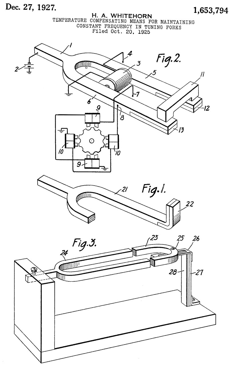
1653794 Temperature-compensating means for maintaining constant frequency in tuning forks, Whitehorn Homer A, Western Electric Co, Dec 27, 1927, 84/409, 84/457, 310/19 - used in multiplex telegraph system driving an impulse motor of the La Cour type (Wiki) motor. A bi-metal strip is used either at the tine ends or the support for a horseshoe magnet.
see La Cour patent 203423 below.
1284219 Starting device for La Cour motors ("Phonic Wheel"), George R Benjamin, Western Union Telegraph Co, Nov 12, 1918, 318/701, 318/400.4, 318/400.8, 310/41 -
When the Hand Lever (11) is pressed and held down and the flywheel spun clockwise, the auxiliary contacts keep the motor spinning, Once up to speed the hand lever is released and the tuning fork provides the electromagnet switching.
Note that opposite pairs of electromagnets (4 & 4)are wired together. The vertical pair (3 & 3)is driven then the horizontal pair (4 & 4). Note the armature (2) has a lobe pitch that does not match the spacing between a pair of electromagnets. For example the top pair (3) is shown with an armature lobe aligned with the left pole piece, but the right pole piece is not aligned with the adjacent armature lobe.
Modern stepping motors (Wiki) work in this way. A more complex drive waveform for each electromagnet would eliminate the need for the starting hardware.
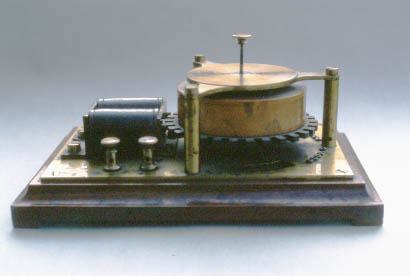
Photos courtesy of the Poul la Cour Museum
Fig 1 Motor
Fig 2 Motor
Fig 3
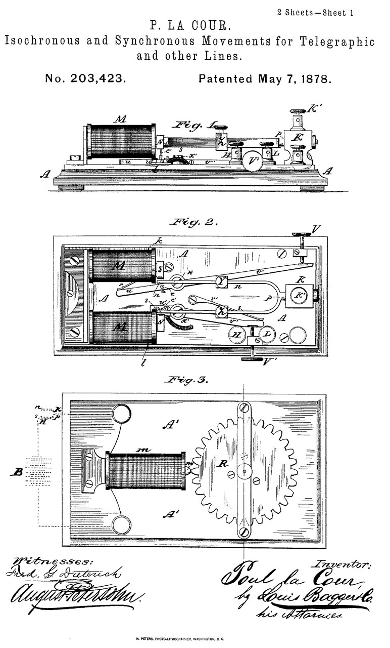
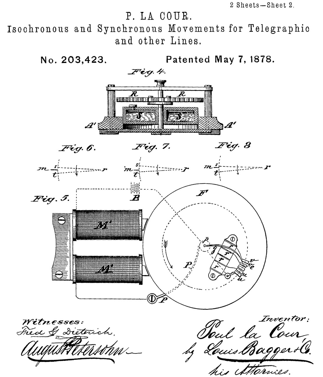
203423 Improvement in isochronous and synchronous movements for telegraphic and other lines, Poul La Cour, May 7, 1878, 388/830; 310/163; 318/161; 318/700 -
Fig 1 & 2 are of the tuning fork driver for one or more motors.
Fig 3 & 4 are of the motor.
Fig 5 is for an addition that compensates for slip of one or more teeth for a higher power motor.
Fir 6, 7 & 8 all look the same to me, but are supposed to represent in-phase, lagging or advancing.
Fig 3 shows a chamber filled with Mercury that helps the motor start and get up to speed. This may not have worked very well since Western Electric has a patent (1284219 above) titled Starting device for La Cour motors.
The system is shown here:
302502 Synchronous telegraphy, Poul La Cour, Jul 22, 1884, 370/304 - uses the above tuning fork and motor, but it's not clear how the wheels at each telegraph station are synchronized. Synchronization was a big part of stock ticker patents.
The Poul La Cour Museum in Denmark -
1828660 Method of and apparatus for driving tuning forks, Buckingham William D, Homer Edward C, Western Union Telegraph Co, Oct 20, 1931, 84/409, 984/260 - force along axis of base.
1906985 Vibratory frequency standard, Marrison Warren A, Western Electric Co, May 2, 1933, 331/156, 310/25, 333/200, 84/409 - frequency standard where fork is mounted resiliently mounted & with Sine wave output.
1912343 Tuning fork temperature compensation and frequency adjustment, Buckingham William D, Western Union Telegraph Co, May 30, 1933, 84/457, 984/260 - by a special mounting
1913331 Tuning fork drive, Buckingham William D, Western Union Telegraph Co, Jun 6, 1933, 84/733, 84/743, 84/409, 331/156 - drive up/down at stem
1937583 Oscillation generator, Norrman Ernst B, Rca Corp, Dec 5, 1933, 331/156, 84/409, 331/69, 331/157, 331/185 - 3 aluminum boxes with insulation and controlled temperature + damping factor 4 to 15X lower than standard tuning forks (see fork dimensions in Fig 1 & Fig 2). An optional construction is to use a magnetostrictive bar (Fig 4) instead of the tuning fork.
1956350 Electrical musical instrument, Hammond Laurens (Hammond Organ), Apr 24, 1934, 84/601, 84/DIG.400, 200/17.00R, 84/715, 307/27, 84/DIG.250, 307/1, 84/433, 310/170, 984/355 - uses tuning-fork w/stem drive (Fig 15) to allow operation from a DC power source and can be used to tune the organ to match other instruments.
1958071 Electrically driven vibrator, Scofield Philip F, Heintz & Kaufman Ltd, May 8, 1934,
1963719 Mechanical vibrating element, Schelkunoff Sergei A, Bell Telephone Labor Inc, Jun 19, 1934, 84/402, 984/260, 367/191, 310/26 - loop = two tuning-forks connected at the tips of the tines.
2015410 Vibrating system, Harold R Prescott, Continental Oil Co, Sep 24, 1935, 84/409, 368/202, 331/156, 367/186, 310/25, 367/178, 368/167 - 100 Hz time marks for seismic oil exploration.
By choosing the base (1) material and the tuning fork (13) material and the spacing (dimension d) between supports (3) temperature compensation is achieved. Similar to the Harrison pendulum clock temperature compensation (Wiki).
2034787 System for generating alternating current, Williams Jr Albert J, Leeds & Northrup Co, Mar 24, 1936, 331/156, 310/25, 331/183, 84/409 - magnetic field away from tuning-fork.
2049179 Frequency generator system, Burrell Stallard, Bell Telephone Labor Inc, Jul 28, 1936, 331/156, 331/183, 330/145, 330/164 - coil axis parallel to tines?
Controls the drive power at constant level independent of power supply variations.
2147492 Oscillation generator, Mead Jr Milton S, Gen Electric, Feb 14, 1939, 331/156, 327/530, 310/25, 310/19, 358/416, 84/409, 327/331, 327/322, 968/481 - constant drive current leads to better frequency stability.
2247960Tuning fork, Eugene Michaels Simon, Bell Telephone Labor Inc, Jul 1, 1941, 84/409, 310/25, 984/260, 310/328 -
2300271 Oscillator with stabilized feedback, James N Whitaker, RCA, 1942-10-27, - two electromagnets, one for tuning fork drive, one for sensing
2309853 Rate and attitude indicating instrument, Norden Elwood, Lyman Joseph, Sperry Gyroscope Co Inc, Filed: Apr 10, 1941, Pub: Feb 2, 1943, 73/504.15, 33/360, 33/351, 73/178.00R, 33/300 - Gyroscope
2424864 Vibration responsive apparatus, Robert C Treseder, 1947-07-29, - by combining 2 reeds with slightly different Fo a broader band of frequencies is covered.
2547026 Vibrating reed structure, Marion R Winkler, Motorola, 1951-04-03, 335/90, 335/92, 335/97 - includes plots of frequency, signal strength & Q (30 to 300)
2547027 Vibrating reed controlled oscillator, Marion R Winkler, Motorola, 1951-04-03, 331/156, 310/25, 984/379 -
2556342 Mounting for tuning forks, Dickran Sebouh, Filed: May 5, 1944, Pub: Jun 12, 1951, 84/409, 84/457, 984/260 - attach at nodal points
2686874 Electrical circuit arrangement for standard frequency sources, Eric Thomas, Arthur Phillips, Needham Jack, Muirhead and Co, 1954-08-17, 331/156 - similar to RCA 2300271.
2687338 Synchronous time system for oscillographs, Davis William L, Hathaway Instr Company, Aug 24, 1954, 346/107.4, 250/208.4, 324/88, 318/85 -
GB1967955A means for controlling the amplitude of vibration of an electromagnetically maintained tuning fork vibrator or the like,Donald Crisp Gall, Jack Sutcliffe, H TINSLEY AND CO Ltd, 1955-07-07 ,
2707234 Tuning fork oscillators, Frank Dostal, American Time Products Inc, Apr 26, 1955, 331/69, 331/156, 331/176, 324/76.49, 368/167 - Gyroscope
2817779 Drive and mounting means for a tuning fork structure, Barnaby Roland E, Morrow Charles T, Sperry Rand Corp, Dec 24, 1957, 310/25 - Gyroscope


Calls:2843742 Device for maintaining mechanical oscillations, Meyer Cluwen Johannes, Philips Corp, Jul 15, 1958, 318/127, 318/160, 368/158, 331/181, 318/132, 331/116.00M, 318/130, 310/39, 310/36, 968/475 - a very simple circuit with a battery, one transistor but two coils, one for sensing and one for driving a clock motor. The drive pulse is at exactly the zero position of the magnetic balance wheel - spring. When driven at the zero position variations in the amplitude of the drive pulse have a minimal effect on the frequency of oscillation.
2513340 Angular velocity responsive apparatus, Lyman Joseph, Sperry Corp, Jul 4, 1950, 73/504.16 - Gyroscope
2683596 Rate of turn instrument, Roland E Barnaby, Charles T Morrow, Lloyd A Nevala, Sperry Corp, Jul 13, 1954, 73/504.16, 55/359, 310/15, 336/30 - Gyroscope
2753173 Turn rate measuring instrument, Roland E Barnaby, Charles T Morrow, Sperry Rand Corp, Jul 3, 1956, 73/504.16, 84/409 - Gyroscope
2888582 Tuning fork oscillator, Max Hetzel, Bulova Watch Co Inc, Filed: Jun 19, 1953, Pub: May 26, 1959, 310/25, 968/481, 984/260, 968/482, 968/483, 84/409, 968/486 -
2928308 Means for controlling the frequency of a tuning fork, Josiah J Godbey, Priority: 1954-03-12, 84/409 318/132 331/177R 968/486 84/674 318/114 331/156 310/25 - vacuum tube ckt.
2956242 Tuning fork oscillator, Grib Boris F, Philamon Lab Inc, Oct 11, 1960, 331/156, 331/177.00R, 333/138, 331/182, 331/135 - 1E-7 adjustments made by changing phase of tube circuit feedback.
3085168 Tuning fork, Jones Albert C, Lingel Frederick J, Troup Peter B, Gen Electric, Apr 9, 1963, 310/25, 984/260, 331/156, 84/409 - for 400 Hz aircraft AC power supply
3091151 Electromechanical oscillators, John A Cunningham, 1963-05-28, 84/457; 331/156; 984/260; 84/409 - temperature compensation by adjusting the electromagnet air gap.
3122047 Tuning fork, Jones Albert C, Lingel Frederick J, Troup Peter B, Gen Electric, Feb 25, 1964, 84/409, 984/260, 84/457 - 400 Hz aircraft small size
3435609 Frequency regulator for tuning fork drive system, Philippe G Kueffer, General Time Corp, 1969-04-01, speed controlled by tweaking the electromagnet air gap on tuning fork - transistor circuit almost a decade after the Kunko pendulum clock.
3493292 Tuning fork structures, Dostal Frank, Bulova Watch Co Inc, Feb 3, 1970, 359/230, 331/155, 331/156 -
6194817 Tuning-fork vibratory gyro, Masanori Yachi, Yoshio Satoh, Hiroshi Ishikawa, Yoshitaka Takahashi, Kazutugu Kikuchi, Fujitsu Limited, Feb 27, 2001, 310/370, 310/351, 310/345 -
Deagan Tuning Fork Patents
A 440 Hz fork with tuneable cylindrical resonator showed up on eBay. It has a a long list of patent numbers on the base. Here they are:
Date
No. & Title
Date
No. & Title Aug 6, 1880
Feb 13 1917
Mar 6, 1900
644817 Musical instrument
May 29 1917
May 21 1901
674604 Musical instrument May 29 1917
Jul 28 1903
734676 Musical instrument Jul 17 1917
Dec 15 1903
747340 Musical instrument Jul 24 1917
Dec 16 1903
Sep 18 1917
Nov 8 1904
Apr 16 1918
Apr 24 1906
818874 Musical Bell
Jan 14 1919
Sep 3 1907
864771 Musical Bell Jan 21 1919
1291777 Hammer
Jun 9 1908
890341 Musical Bell Jan 21 1919 1291778 Percussion musical instrument
May 9 1908
Feb 11 1919
Feb 11 1913
1052713 Musical Bell Feb 11 1919
Jun 16 1914
1100671 Musical Chimes
Feb 11 1919
Jun 16, 1914
1100672 Musical Bell
Apr 29 1918
Jul 21 1914
1104478 Musical instrument Jan 25 1921
D56959 Master tuning-fork and supporting-resonator
Feb 2 1915
Feb 22 1921 1369268 Percussion musical instrument Feb 9 1915
1128112 Piano without strings
Dec 6 1921
Feb 29 1916
1173782 Piano without strings
Jan 3 1922 1402219 Apparatus for tuning musical instruments, 84/454; 984/260 Feb 29 1916 1173783 Percussion musical instrument
Jun 20 1922 1419919 Master tuning-fork and supporting-resonator Feb 29 1916 1173784 Xylophone
1173785 Percussion musical instrument
Aug 7 1923
Dec 5 1916
1207281 Musical instrument of xylophone type
Nov 6 1923
Feb 13 1917
May 5 1925
MEMS (Wiki)
Note that the frequency of a pendulum depends on the acceleration along the longitudinal axis (Wiki, Pendulums). Hence they can be used as accelerometers.
But there's no acceleration term in the frequency of a tuning fork (Wiki)? Not clear how double-ended tuning fork (DETF) works.
When a tuning fork is used as a gyroscope (Wiki) the tines of the tuning fork move out of their normal plane, but I think the DETF accelerometer works in plane?
Precursor patents
2309853 Rate and attitude indicating instrument, Lyman Joseph, Norden Elwood, Sperry Gyroscope, App: 1941-04-10, W.W. II, Pub: 1943-02-02, - gyro based on vibrating rod
RE22409 (2309853) Rate and attitude indicating Instrument, Joseph Lyman, Elwood Norden, Sperry Gyroscope, - gyro
2455939 Device for detecting turns or Measuring the rate of turn, Frederick William Meredith, S. Smith & Sons, UK App: 1942-07-27, Top Secret, Pub:1948-12-14 - twisting a tuning fork, rate of turn sensor, i.e. replaces gyroscope.
Calls:2928668 Accelerometer, Blasingame Benjamin Paul, 1960-03-15, - double-ended tuning fork (DETF) "In simplest form, the invention is a vibrating reed which is caused to vibrate at its natural frequency. The natural frequency of such a device is a simple function of the inertia of the reed, its spring constant, and the acceleration of the reed along the longitudinal axis of the reed." ??? Reference??? This is the heart of a DETF MEMS accelerometer.
2178259 Lithographer's press
2249649 Fatigue testing apparatus
2277037 Fruit ripeness tester
RE22409 Rate and attitude indicating original patent: 2309853 Rate and attitude indicating instrument, Lyman Joseph, Norden Elwood, Sperry Gyroscope, 1943-02-02, - gyro based on vibrating rod
2361396 Vibration fatigue testing machine - measures out of plane movement of vibrating rod
MEMS patents
3269192 Tuning fork digital accelerometer, Jr Hamilton Southworth, John C Stiles, General Precision Inc, 1966-08-30, - quartz cylinder housing, DETF
3614677 Electromechanical monolithic resonator, Raymond J Wilfinger, IBM, 1971-10-19, -
4479385 Double resonator cantilever accelerometer, Dale R. Koehler, DOE, 1984-10-30, - "A digital quartz accelerometer includes a pair of spaced double-ended tuning forks fastened at one end to a base and at the other end through a spacer mass."
11112246 Torsional oscillator micro electro mechanical systems accelerometer, Clinton Blankenship, Army, 2021-09-07, -
Audio Frequency Shift Keying Tones
In the 10/13/2021 digest of the GreenKeys (Tone frequency history?) list server there's a discussion of why the AFSK tones were 2125 and 2975 Hz (850 Hz shift.
2125 = 17 x 5 x 5 x5 = 425 x 5
An observation is that:
2975 = 17 x 5 x5 x 7 = 425 x 7
And a discussion of the use of a 425 Hz tuning fork. But the current musical "A" tuning fork is 440 Hz.
This is related to the NBS 1,000 CPS frequency standard above in that it uses a tuning fork.
Speed of Light (Wiki)
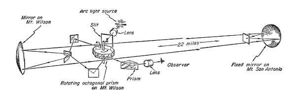
I'm adding this to the Tuning Fork web because I learned that Albert Michelson used a tuning fork as part of his SoL measurements at Mount Wilson (Wiki).
Mr Clarke, I am researching Albert Michelson’s speed of light measurement experiments conducted at Mount Wilson in California during the early 1920’s.For those experiments, he used a mirror mounted on an electric tuning fork as a stroboscope to adjust the speed of a spinning mirror. He was also to possibly have controlled the tuning fork with a tube driven oscillator. Have you ever seen any devices related to him or like these in your research?
Thanks for your help.
Michael Lichtenberger
Museum of Experimental Science
Michelson
A.A. Michelson (Wiki) made many attempts at measuring the speed of light. He studied Leon Foucault's (Wiki, SoL, Gyroscope) speed of light measurements.
See Ref. 6 below.
Fig 1 Setup
Fig 2 8-Sided Mirror. Note two air nozzles used.
Main nozzle for 31,800 RPM and retarding nozzle to adjust speed.
The Train Gyro uses a very similar air turbine. YouTube: Train Gyroscope Sperry p/n: 647168, 1:44
The aircraft Turn & Slip Indicator also uses an air turbine.
Albert A. Michelson Patents
921137 Range-finder, Albert A Michelson, 1909-05-11, -
1030846 Range-finder, Albert A Michelson,1912-06-25, -
1279396 Art of protecting the ear-diaphragm and apparatus therefor, Albert A Michelson, John Gordon Wilson, 1918-09-17, - Valve normal hearing, but blocks gun shots.
Stoll
TED talk includes Speed of Sound measurement.
Clifford Stoll (Wiki, The Cuckoo's Egg) made a SoL measurement using laser pointer diode modules. His description follows.
Also see Cliff's Acme Klein Bottle web page where I got a Chinese Spouting Bowl.
Hi Brooke,

   Wow - your page on tuning forks is wonderful!  I had no idea of the widespread use of these in 19th century physics (well one case I know about:  Doppler's public demonstration of the doppler effect using a small brass band on a train car.)

   My long-ago speed of light (not shown in that Ted talk) was in an 8th grade science class; the next year I refined it when I taught a handful of 14 year old home-school kids, "Garage Physics".

   In short, I had the kids aim a cheap laser-pointer at a distant mirror.  They measured the distance from laser to mirror using a meter stick (well, a tape measure - it was 15 meters away, in the crawlspace under my house)

   The laser pointer was driven by a signal generator and 1 MHz (so it turned on and off about a million times a second).

   About 5 cm in front of the laser-pointer, we put a glass microscope slide at 45 degree angle to use a beam-splitter.

   The short-path beam (from the beamsplitter) goes directly into a photo-diode.

   The long-path beam (to the far-away mirror and back) goes through a convex lens and then a second photo-diode.  (need a lens because the beam has expanded from 1mm diameter to about 100mm and subsequently dimmer!)

   The outputs from the two photodiodes (biased to almost turn-on) goes into the 2 inputs of a dual-trace oscilloscope.

    The osicilloscope beams show the time difference in the turn-on time of the two beams.

        Each beam shows a square wave, turning on and turning off.

        The time difference between these square waves is the time-of-flight of the photons.

    Measure the distance from beamsplitter to distant mirror (times two).  Distance divided by time is speed.

Lots of gotchas!  First, most laser pointers can't be switched at 1MHz ... I found only one in 5 could (of course, they're really cheap, so I bought a few dozen and chose the best)
Second, what oughta be a square wave gets rounded off at the turn-on and turn off, due to lousy frequency response of the laser as well as the photodiodes.
Third, the photodiodes are really finicky to set up and bias.  They need amplifiers.  What a pain!
Finally, the optical system has to be really stable (clamped to a concrete block!)

All in all, a fun project for teenage science nerds.  They measured the speed of light to 3.05 x 10^8 m/sec.  Then we had a great discussion on why everyone else was wrong.

(And then I explained why it's now impossible to measure the speed of light.  Since the speed of light is a primary standard since 1988 ... so what were we really measuring in this experiment?


Gotta get ready for a trip to the eclipse (we're having our house painted while traveling, so lotta prep-work this month!

Cheers,
-Cliff
On Mar 8, 2024, at 8:56 AM, Brooke Clarke wrote: Hi Cliff: I was asked about Albert Michelson’s speed of light measurement experiments and in particular his use of tuning forks. That's because I have a web page about them. https://prc68.com/I/TuningForks.html This reminded me of your great TED talk measuring the speed of sound, because you didn't have time for the SoL setup. Is there somewhere that you have documented how to make the SoL measurement? PS I'm the happy owner of a Chinese Spouting Bowl and Klien bottle. https://prc68.com/I/ChineseSpoutingBowl.shtml -- Have Fun, Brooke Clarke https://www.PRC68.com axioms: 1. The extent to which you can fix or improve something will be limited by how well you understand how it works. 2. Everybody, with no exceptions, holds false beliefs.
G. Boulitte
2025Jan23 eBay auction for a 1910 electromagnetic tuning fork by G. Boulitte.
Fork stamped "100 VD"
White Label: Condenser
Three Pairs of terminals on other side: Shunt, Signal & Pile
Marked: G. Boulitte, Paris, France
Patents by G. Boulitte
FR402572A
Method for the observation, study of the form or measurement of oscillations in systems where, apart from these oscillations, variations in the mean value or speed of the oscillating quantity occur; and apparatus for the application of this method, in particular to sphygmomanometry and sphygmography 1909-10-12
FR436569A Improvements to spirometers (Wiki) and similar devices 1912-03-30
FR442934A Improvements to devices such as, in particular, devices for controlling, using an electric motor, recording devices 1912-09-12
FR456976A
Improvements made to systems, such as, in particular and above all, laboratory centrifuges, comprising a transmission by belt or the like and with fixed and idle pulleys; as well as, alternatively, to products being prepared using said centrifuges 1913-09-09
FR526122A Improvements made to clicks and similar systems 1921-10-01
FR526121A Improvements made to gear changes such as, in particular, those to be understood by devices for controlling the cylinder of recording devices
1921-10-01
FR525804A Improvements made to devices - and in particular to differential … 1921-09-28
FR528124A Improvements to lubricant distribution systems in machines 1921-11-07
FR525856A Improvements made to electrical measuring devices, particularly oscillographs (includes electromagnet)
1921-09-28
FR538168A Improvements to recording devices with a recording cylinder that can be tilted at will
1922-06-06
FR543067A
Improvements made to the means for ensuring the protection of electrical circuits against parasitic currents, in particular those to be included in the galvanometric circuits
1922-08-26
FR551084A Improvements to devices comprising a pneumatic belt, in particular to sphygmomanometers (Wiki) comprising a pneumatic cuff 1923-03-27
FR580822A Improvements to medical devices for insufflation and aspiration of gas (air, … 1924-11-17
FR620502A Improvements made to devices for measuring gas volumes, in particular to … 1927-04-25
FR641355A
Improvements to injection devices 1928-08-02
FR642930A
Improvements made to gas analysis devices 1928-09-06
FR653691A Improvements in sensitive tape unwinding cameras, especially those used for … 1929-03-25
FR653692A
Improvements made to devices for mounting incandescent electric lamps in their … 1929-03-25
FR661575A Improvements to blood pressure measuring devices 1929-07-26
FR674332A Improvements to medical electrical devices 1930-01-27
FR674331A Improvements to straps and belts attachment systems 1930-01-27
FR697126A
Improvements to mechanical amplifiers 1931-01-12
FR710199A Improvements made to manometric devices for the observation or measurement of … 1931-08-19
BE381650A Improvements made to piston pumps, in particular to pumps for artificial … 1931-08-31
FR721035A Improvements to high-frequency electrical devices, especially those used in medicine and surgery 1932-02-26
FR721036A Improvements made to spark gaps, in particular those intended for the production of high frequency currents 1932-02-26
FR721279A Improvements to high frequency devices, especially those used in medicine and surgery 1932-03-01
US1924104A Manometric apparatus 1933-08-29
FR737653A Improvements made to objects with tightening loops, in particular to … 1932-12-15
FR740822A
Improvements to paper tape pen recording devices, in particular to devices for studying arterial pressure 1933-02-01
FR750569A Improvements made to manometric devices, in particular those for medical uses 1933-08-12
FR784218A Improvements to tube amplifiers, especially those for electrocardiographs 1935-07-22
BE414336A Improvements made to pneumatic devices used for surgery, in particular for eye … 1936-04-30
FR811462A
Method and apparatus for making a living being inspire a gas or gas mixture, in … 1937-04-15
FR816619A Method and apparatus for anesthesia 1937-08-12
FR817417A Pneumatic device for surgery 1937-09-02
FR818186A Apparatus for renewing the fluid contained in a container, in particular for … 1937-09-20
FR827365A Device for artificial pneumothorax 1938-04-25
FR848920A
Respiratory 1939-11-09
FR854559A Micro mist generator device for therapeutic or industrial applications 1940-04-18
FR861474A Injection devices such as syringes used in surgery 1941-02-10
FR865648A
Automatic analgesia device 1941-10-27
FR885960A Chronograph electric recorder -eSpaceNet - uses a motor, not tuning fork.
1943-09-30
FR1018670A Photographic, cinematographic, radiographic, electrocardiographic, or other camera, with receptor for the immediate development of sensitive exposed surfaces 1953-01-12


Related
Quartz Clock -
Chinese Spouting Bowl & Tibetan Singing Bowl -
Crystals
Crystal Equivalent Circuit
Crystal Impedance (CI) Meters
Crystal Temperature Compensation Patents
Joule Thief - Motor Circuits - simple one transistor control of a
Geek Stuff: Zendulum - a spherical magnet rolls in a curved track - very similar to a pendulum.
the TS-65D/FMQ-1 is related to the weather balloon tracking equipment, including PIBAL theodolites, radiosondes, CRT-1 sonobuoy, Roswell Incident,
General Radio Sound Measuring Equipment (Also pages about: GR Strobotac & Harold "Doc" Edgerton)
Quartz Kitchen Clock Movement -
Pendulums
Military Audio
Military Audio Accessories
U-229 Audio Accessories
U-229 Pinout by Function
phones
Sound Powered Phones & early loud speakers
TS-585 Audio Level Meter
HP 4395A Network, Spectrum & Impedance Analyzer
Beltone 12D Audiometer -
Sound Powered Telephone - and the development of early speakers
Crystal Radios and early loudspeaker
Teledyne Avionics TA-3D Acoustic Impedance Meter - hearing test with control of atmospheric pressure in ear.
Sonobuoys - CRT-1B Sonobuoy
Radiosondes -
Pilot Balloons -
Vibrotest 218 Insulation Tester (Megger) 100 Megohms - 500 Volts - Uses a resonant reed (half a tuning fork) to both make and break the primary circuit of a transformer and to mechanically rectify the transformer output back into HV DC. PS the back EMF (Wiki) shut down the HP #3617A power supply with the Over Voltage Protection LED turned on. It may not be a good idea to power devices that have inductance and make/break circuitry from modern solid state power supplies.
References
Ref 1. On the Sensations of Tone as a Physiological Basis for the Theory of Music, Hermann von Helmholtz, 1912 -
Ref 2. The Theory, Design and Construction of Induction Coils, H. Armagnat (Translated by O.A. Kenyon), 1908
Ref 3. FUNDAMENTALS OF ACOUSTICS, 4TH ED,Lawrence E. Kinsler, Austin R. Frey, Alan B. Coppens, James V. Sanders, 2009
Ref 4. Journal of the Optical Society of America, Volume 6, Part 1 - 1922 An Electron Tube Tuning Fork Drive, E.A. Eckhardt, J.C. Karacher & M. Keiser pg 949.
Ref 5. Handbook of Piezoelectric Crystals for Radio Equipment Designers, PB-111586-R, Buchannon, Oct 1956
Ref 6. 1924 Other Hand: Historic Speed of Light measurements in Southern California - Preliminary Experiments on the Velocity of Light, A.A. Michelson, 1924, pg 257 (pdf pg 2) describes the tuning fork part: "The observation will then consist in obtaining this speed (of octagonal mirror, nominally 530 RPS (31,800 RPM), in the present case by stroboscopic comparison with an electric fork making 132.25 vibrations per second (7935 vib/min), the latter being controlled by comparison with a free seconds pendulum, which last is compared with an invar gravity pendulum furnished and rated by the Coast and Geodetic Survey."
Ref 7. 1927 Astrophysical Journal, Vol LXV, pp 1-22, 1927: Measurement of the Velocity of Light Between Mount Wilson and Mount San Antono, A.A. Michelson, F. Pearson. "...the arrangement of the apparatus being essentially the same as in the preliminary work, except that instead of driving the electric fork (N-132) by make and break between platinum points, the fork (N=528) was driven by a vacuum-tube circuit, giving a rate far more nearly constant. This rate was measured buy comparison with a free pendulum furnished by the United States Coast and Geodetic Survey, as in the privious work; but with an important improvement in the stroboscopic method. This consists in allowing the light from a very narrow slit to fall on a mirror attached to the pendulum, forming, by means of a good achromatic lens, an image of the slit in the plane of an edge of the fork, where it is observed by an eyepiece. This method of making the stroboscopic comparison was found to be far more convient and accurate than that described in the work of last year."
Ref 8. 1935 Astrophysical Journal, Vol 82, pp. 26-61m 1935: Measurement of the Velocity of Light in a Partial Vacuum, A.A. Michelson, F.G. Pease & F. Pearson - Systems of Measurement pg 269 (pdf pg 13) Measurement of Time, Mirror speed control, True period of free pendulum, Time of light transit, Measurement of distance, Typical observation
Ref 9. Tele - Tech 1953 April new patents: 2583542 Vibratory reed-controlled oscillator, Lee G Bostwick, Bell Labs, 1952-01-29, - multiple reeds are used for decoding audio tones (Touch Tone?) for mobile use. also see 1906985.
Ref 10. 2314 The Accutron Mechanism, 7:44 -
Links
120 Years of Electronic Music - Helmholtz Sound Synthesizer. Max Kohl. Germany, 1905 -
Naval Postgraduate School Physics - Ph 3451: Acoustics - Lecture 19 - Helmholtz Resonators - text: Ref 3.
Naval Postgraduate School Physics - PH3119 Tuning Fork Part 1 - note drive and sense coils at right angles to each other.
Naval Postgraduate School Physics - Helmholtz Resonator and other Maintained Oscillators -
NPS Physics - Ph 3451: Acoustics - Physics Experiment 2 - Helmholtz Resonator Part 1
Instruments for Natural Philosophy - Tuning Forks
PRC68, Alphanumeric Index of Web pages, Contact, Products for Sale
Page Created 15 December 2017