Background
In-Ear-Monitor
Description
Element
Remco Toy Sound Powered Telephone
Wheeler
Insulated Wire Handset
Control
Instrument Co. Handset
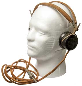
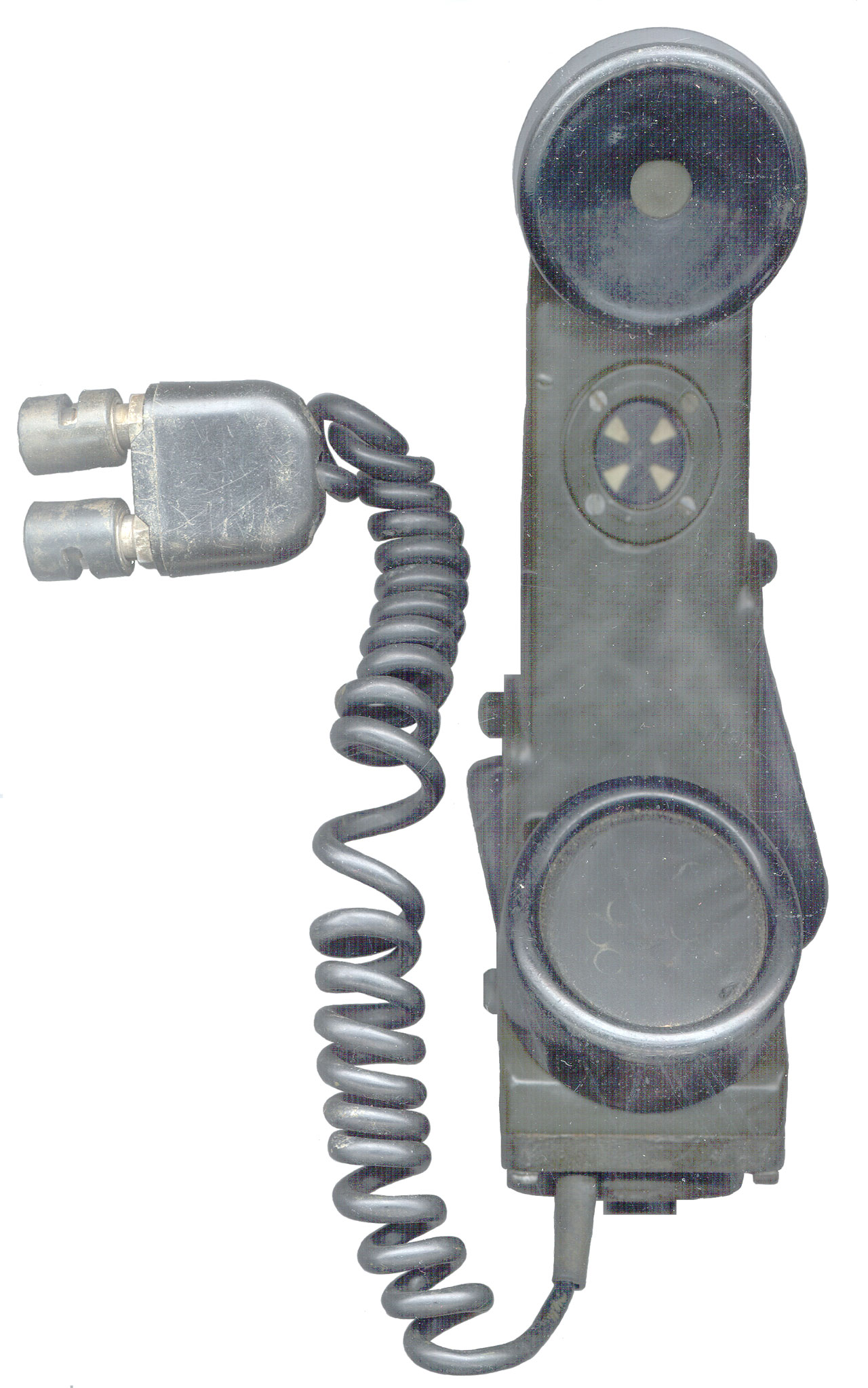
Chest Set
Dynalec H-200/U Sound Powered
Chest Set
H-203 Handset
TP-3 Sound Powered Telephone
Set
TA-1 Field Phones
Baldwin
Speaker Driver
Baldwin Driver + Horn
Baldwin Headphones
Dictograph
Western Electric No. 555
Receiver
Western
Electric 509w Receiver
Peerless Speaker (Lektophone)
Tivoli Audio
Model One Radio
CCRadio2
Acoustic Research Speakers
A7 Voice of the
Theater Speakers
Freed-Eismann Radio
Speaker FE-50
Kellog S&S Co 178-C Chest Microphone,
65A Earphone & 102 Four Prong Plug
Patents
Electric
Phonograph Pickup Patent 1921
Murdock Headphones
Exponential
Folded Horn
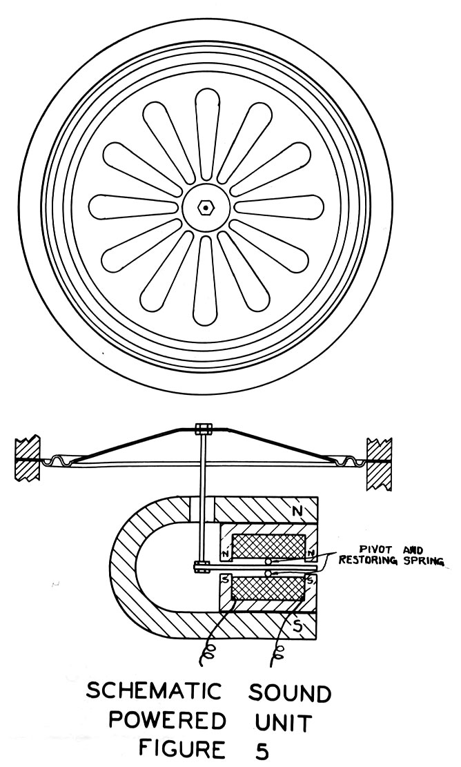
Sound Powered Elements
Murdock
Headphones
Brandes Inc
Henry C Harrison
Condenser Microphone
Throat Microphone
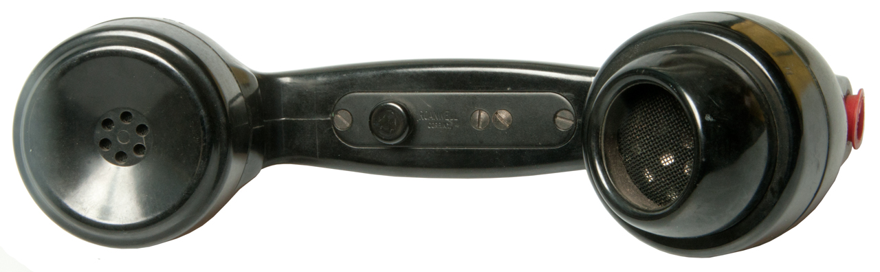
Roanwell
Photos
Brush Development Co
Atwater Kent
Electro-Voice
Bell
Labs
RCA
model 103 speaker
Shure
MC30 Microphone
Testing Spy Mikes
Cheap EarBuds
Knowles Hearing Aid Speakers
ZS10 Pro
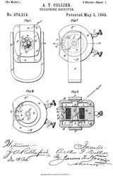
Collier Receiver
Magnavox
National Research Council of Canada
Measuring
Dayton Audio Test System V3
References
Related
References
Links
Background
The Wiki
page for Sound Powered Telephones has a number of
examples of their use and mentions the USCG regulation that
mandates their use on some ships. The idea is to have an
intercommunication system that will work without external
power. This usually is done for reliability rather than
cost savings. The TA-1/PT military
field phone is sound powered. The United States
Instrument Corp. set consists of a chest mounted microphone
and a pair of headphones. It as a Jones type connector
with 2 male pins. Not sure of the application.
Dynalec
still makes sound powered phones.
In military situations where there is a very high level of
background noise, the microphones need to have good noise
cancellation properties. This needs to be combined with
the sound powered aspect for a workable sound powered
telephone system for military applications. Note there
are no switches which may be in the wrong position in a life
threating emergency, i.e. this set is always going to work
without any training.
While the telephone that A.G. Bell
patented in 1876 used what today we call a dynamic
microphone that outputs a voltage (i.e. in a way you could say
sound powered) it was replaced in 1889 by the Edison carbon
granule microphone that had much higher conversion gain, but
required external DC power.
The efficiency of sound powered speakers is much higher than
conventional speakers. Here's the top of page 8 from the
Instruction book for the H-203 handset (1938):
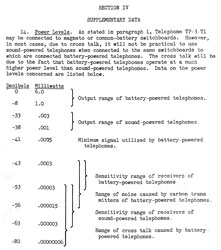
|
Notice that the carbon mike has an
output that's 25 to 33 dB higher than that of a sound
powered mike.
Also, the speaker in sound powered phones is 10 to 20
dB more sensitive than conventional speakers.
|
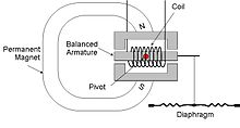
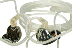
In-Ear-Monitor (Wiki)
Balanced Armature (Wiki)
headphones/ In-Ear-Monitors are very efficient.
The diaphragm is not stressed like with conventional
headphones where a permanent magnet is pulling
it. The professional IEM offer excellent
fidelity along with sound isolation. These are
typically custom molded to fit an individual ear &
high $$$$$. Used by professional musicians.
JH Audio: What
is a Balanced Armature Driver, Part
2 The Guts and The Glory, The
Siren Series: Layla (12 drivers per side)
7194103B
In-ear monitor with hybrid diaphragm and armature
design, Jerry
J. Harvey, Filed: 2005-01-12, Pub: 2007-03-20 -
both diaphragm and balanced drivers
8897463
Dual high frequency driver canalphone system, Jerry
J. Harvey, JERRY HARVEY AUDIO HOLDING LLC,
2004-11-25 - Laya
8925674
Phase correcting canalphone system and method, Jerry
J. Harvey, JERRY HARVEY AUDIO HOLDING LLC,
2015-01-06 - FreqPhase - a similar idea to the Altic
Lansing Voice of the
Theater speaker where the voice coils of the 15"
woofer and the horn driver are in the same vertical
plane to prevent sound cancellation/distortion at the
500 Hz crossover frequency.
|
US20140205131A1 Multi-driver earbud, Apple Inc, 2015-06-09
- in ear uses woofer, midrange and tweeter drivers. Some In Ear Monitors (Wiki IEM)
use a dozen or more drivers to get high fidelity sound (See JH
Audio above)..
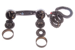
Description
The sound from the speaker's voice powers the phone
so no external power is needed.
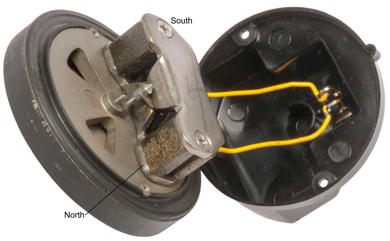
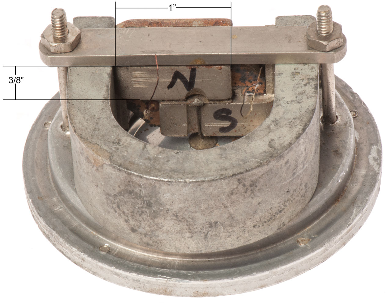
Sound Powered Element
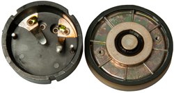
United States Instrument Corp. 1247A G4 Sound Powered
Element. Measures 60 Ohms and makes sound when tested
using the Fluke DMM DIODE test
function (i.e. 1 mA)
Fig 1 Element sitting in cup (no cover)
|
Fig 2 After lifting the element out of
the cup.
U.S. Instrument Corp.
UA1614-11
U.S. Patent
No. 2245511
 |
Fig 3
After removing 2 screws to open back cover
 |
 |
|
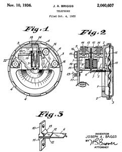
2060607
Telephone, Joseph
A Briggs, RCA,
1936-11-10, 381/411; 381/418 -
electromagnetic type that is rugged and capable of
withstanding severe shocks and blows
The Baldwin design was much harder to make and not as
rugged as this one. |
|
|
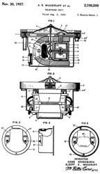
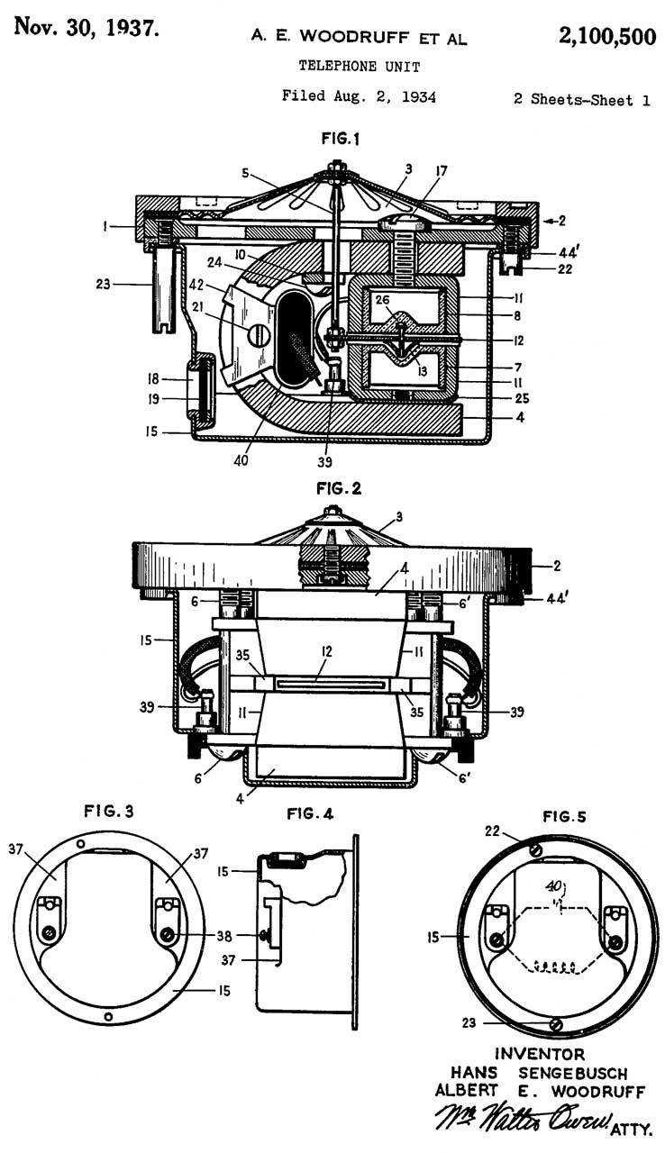
2100500
Telephone unit, Albert
E Woodruff, Sengebusch
Hans, Associated
Electric Lab, 1937-11-30, -
Albert Woodruff worked for Associated Electric Lab
from 1934 till 1941 (Start of W.W II?)
then he started working for Automatic Electric (Wiki:
AE)
and his last patent with AE was 1953.
|
|
|
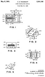
2241106
Sound translating device, Albert
E Woodruff, Associated
Electric Lab,1941-05-06, 335/231; 335/279; 335/281;
335/276 -
|

|
|
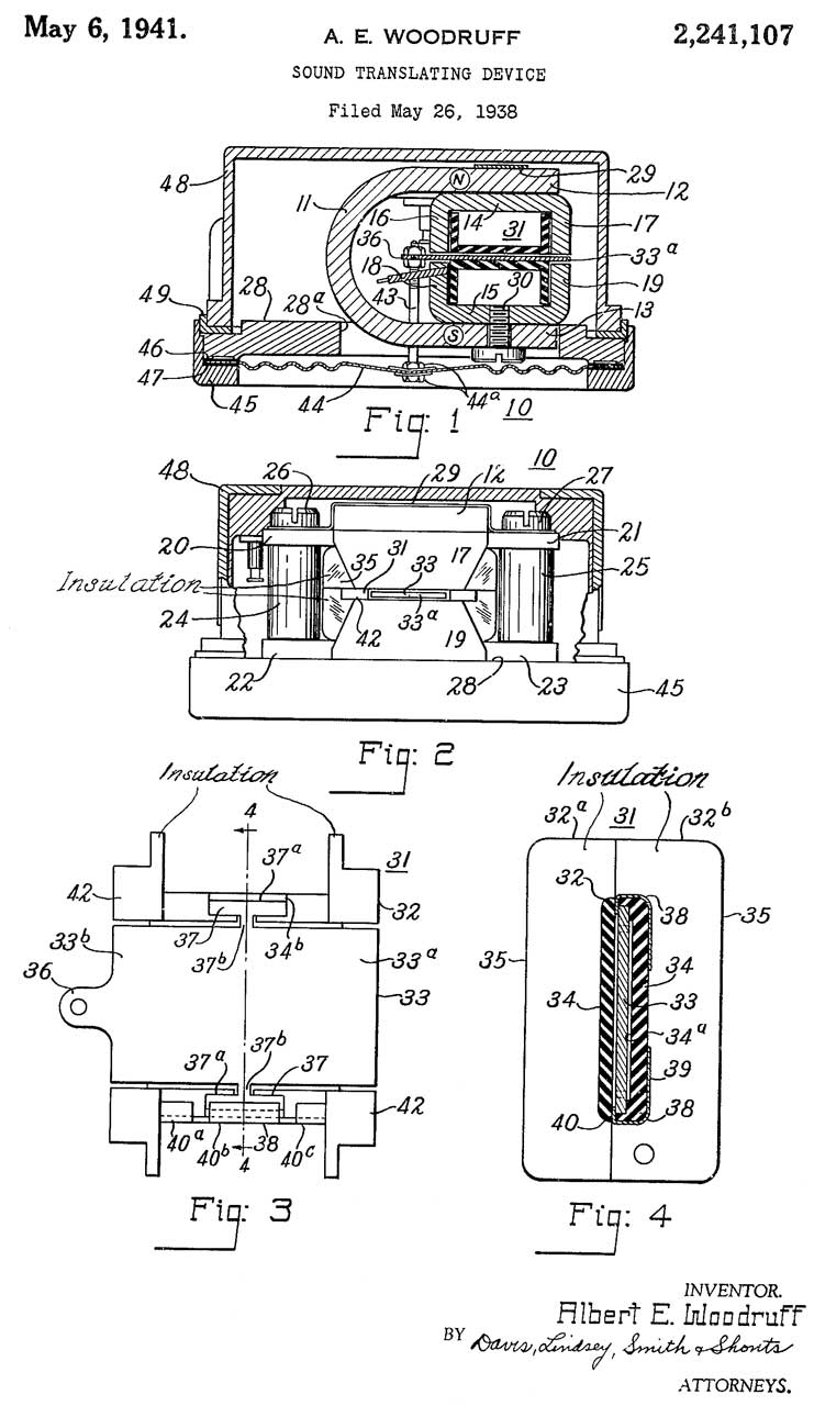
2241107
Sound translating device, Albert
E Woodruff, Associated
Electric Lab,1941-05-06, 381/418; 381/419 - horseshoe
magnet
|
 |
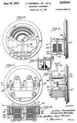 |
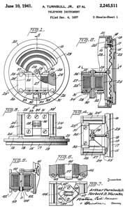
2245511 Telephone instrument, Jr
Arthur Turnbull, Herbert
R Warnke, United
States Instrument Corp, filed: 1937-12-04, Pub:
1941-06-10, 381/418 -
|
 |
|
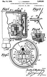
2400281 Electromechanical signal
translating apparatus, Leslie
J Anderson, RCA,
filed: 1940-10-31, Pub: 1946-05-14, 381/346; 181/166;
381/417; |
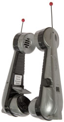
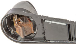
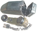
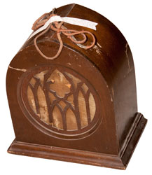
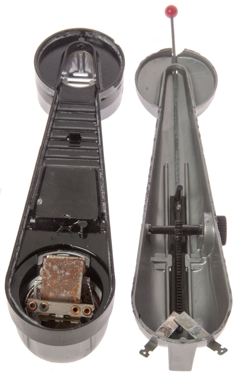
Remco
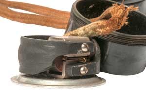
Toy Sound Powered Telephone
This pair of toy sound powered phones was very reasonable
on eBay. The reason is that one of them has a very
poor electrical connection and the other about 11 Ohms, but
steady.
You can see from Fig 2 below that there's only one sound
power element and it serves as both the microphone and
speaker. The problem was they uses a pressure
connection between the external terminals and a pair of
spring contacts.
After using a pencil eraser to clean the terminals and
bending one of the springs out a little the phone halves
were mated and the Ohm meter read a solid 11.7 Ohms. A
few drops of acrylic cement (maybe) will complete the
repair.
Control Instrument Co patent 2109761 uses the same method of using
a single transducer and a speaking tube so it can be used as
both the transmitter and receiver.
Fig 1
|
Fig 2
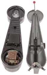 |
Fig 3
 |
|
|
|
US2536179
Magnetic sound-powered telephonic unit, Isaac
Heller, Remco
Ind, Jan 2, 1951, 381/161,
381/418,
381/396
The bottom two illustrations are of how they make a
long bar magnet and break it into small pieces for
use in the element.
|
|
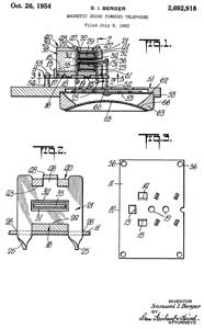
2692918 Magnetic sound powered
telephone, Samuel
I Berger, 1954-10-26, 381/418 -
Put this patent under the Toy phone because Berger has
other patents for sheet metal toys.
Calls:
2245511 see above
2400281 see above
2454425
Magnetic translating device, Benjamin
B Bauer, Shure
Inc, filed: 1943-12-23, Pub: 1948-11-23, 335/231; 335/281; 310/25; 369/148
- dynamic mike
2523775 see below
2536179 see above
2582942 see below
|
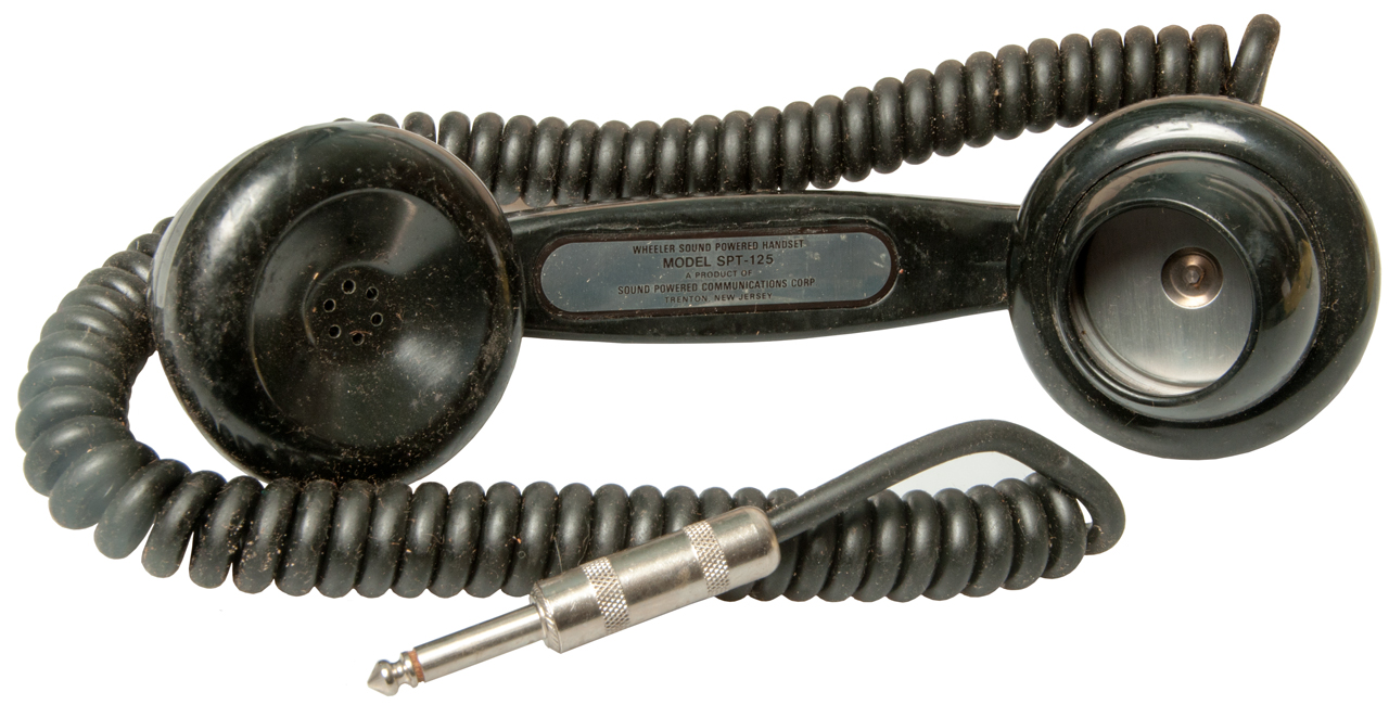
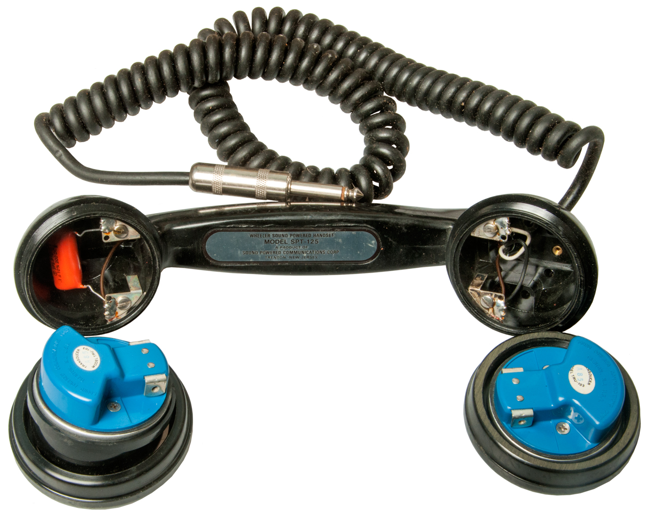
Wheeler
Insulated Wire Handset
AKA: Sound Powered Communications Corp.
SPT-125 with 1/4" Phone Plug
Fig 1 New Old Stock (NOS) SPT-125
|
Fig 2
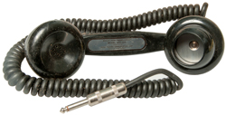 |
Fig 3 Notice the same element for both
talking and listening.
 |
Wheeler Insulated Wire Co. adapted that name in 1922 since
their main product was insulated magnet wire. During the
second world war they made the ‘Marine
‘Raider’ Receiver. (let me know what it is).
Only after the war did they start making sound powered phones.
(Connecticut
Mills).
Electronics magazine, Dec. 1949 - pg 179 Wheeler Insulated
Wire Co. ad for transformers and other products that are
mostly magnet wire, but no sound powered phones.
Fig 1
|
|
|
2492056
Batteryless ringing device, William J
Muldoon, Wheeler Insulated Wire, 1949-12-20, 379/373.01; 340/328; 310/25;
381/162; 381/418 - dial plucks reed which is
coupled to similar reed in Rx set. Vibrating
reed taps bell. Intended for toy phones as well
as short range general applications
|
|
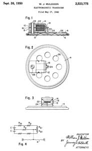
2523775
Electromagnetic transducer, William
J Muldoon, Wheeler Insulated Wire, 1950-09-26, 381/418; 310/25 - |
|
2523769
Calling unit, John
H Maloney, Randall
B Baker, Wheeler Insulated Wire, 1950-09-26, 310/25; 340/333- causes
loud noise in receiver units rather than separate
sound maker
|
|
2533136
Vibratory reed signaling device, William
J Muldoon, Wheeler Insulated Wire, 1950-12-05, 340/384.73; 310/25; 116/167;
379/167.01; 335/93- more powerful ringing
than patent 2492056
|
|
2582942
Electroacoustical transducer, Randall
B Baker, Wheeler
Insulated Wire, 1952-01-22, 310/25 - same
application as 2523775. |
|
2607857
Telephone handset, Randall
B Baker, Wheeler
Insulated Wire, 1952-08-19, 379/433.01; 446/142 - Tx and
Rx units plug in (no screws), toothed wheel for
2523769 signaling
|
|
2634378
Vibratory reed signaling device, William
J Muldoon, Wheeler Insulated Wire, 1953-04-07, 310/29; 340/6.13; 335/252;
335/230; 340/333 - even more powerful,
includes bell
|
|
2808461
Handset, Aldrich
R Thomas, Wheeler Insulated Wire, 1957-10-01, 379/422; 379/395; 379/433.06;
379/433.01- includes a PNP transistor
amplifier in the Tx cavity or can work as sound
powered w/PB switch.
|
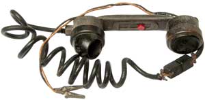
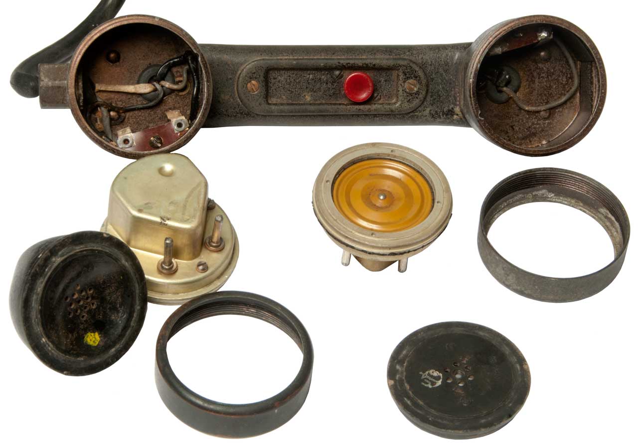
Control
Instrument Co. Handset
Fig 1 Type L
Serial No. 2267
N.D. Control No. d1515, N.D. Insp.
Intermittent connection.
|
Fig 2 inside both elements look the
same.
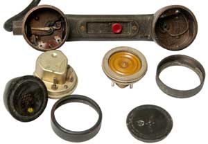
|
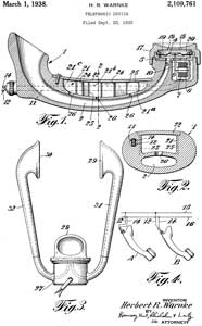 |
2109761
Telephonic device, Herbert
R Warnke, Control
Instrument Co, 1938-03-01, -
The Remco
toy uses the same method of using a single
transducer and a speaking tube so it can be used as
both the transmitter and receiver.
|
|
2115795
Magnetic unit, Herbert
R Warnke, Control
Instrument Co,1938-05-03, - for high power
loudspeaker?
|
|
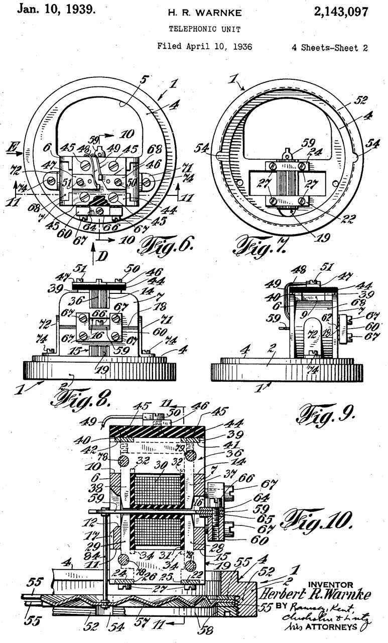
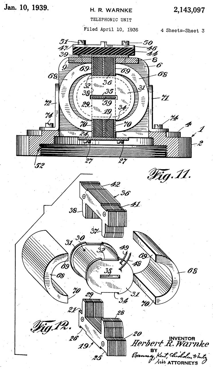
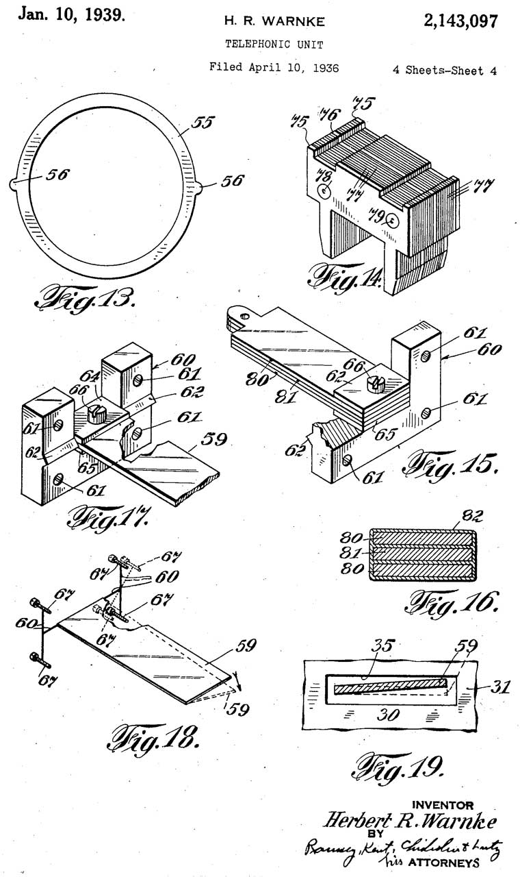
2143097
Telephonic unit, Herbert
R Warnke, Control
Instrument Co,1939-01-10, -
"...capable of Operating as a receiving unit or as a
transmitting unit...high efficiency." |
|
2163161
Magnetic unit, Leslie
H Wadsworth, Control
Instrument Co, 1939-06-20, - "one-piece magnet casting"
- sound powered element (either Tx or Rx).
|
|
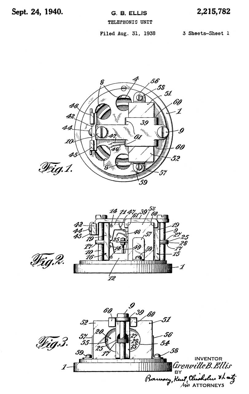
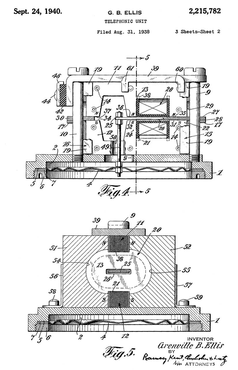
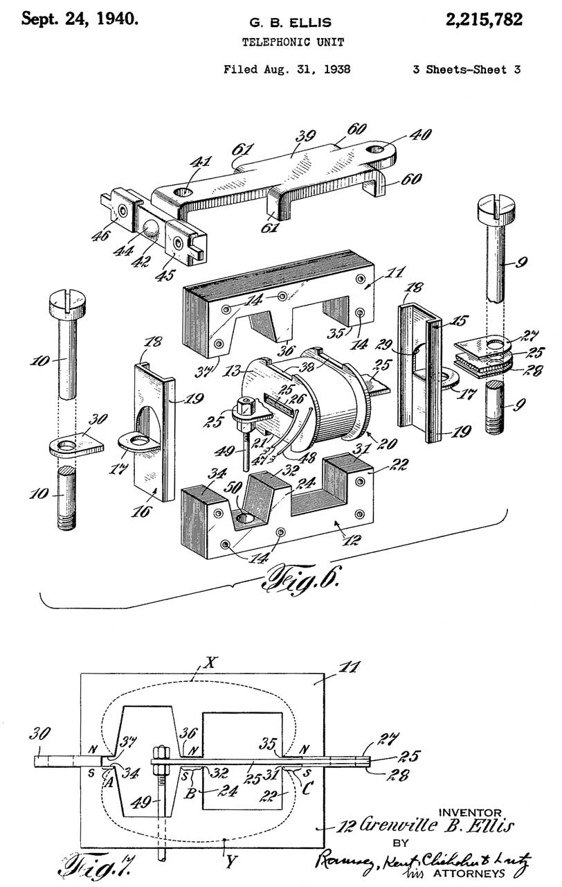
2215782
Telephonic unit, Grenville
B Ellis, Control
Instrument Co, 1940-09-24, - Diminishes
"blasting" like happens with gun fire nearby.
For more patents by G.B. Ellis see Radiosonde
Batteries.
|
|
2358529
Telephone system, William
J Muldoon, Harold
T Stenhammer, Control
Instrument Co, 1944-09-19, - much simplified
based on stepping switches.
|
|
2372801
Selector switch, Harold
T Stenhammer, Control
Instrument Co, 1945-04-03, -
|
|
D140289
Casing for telephone units, William
J. Muldoon, Filed: 1944-08-21, Pub: 1945-02-06,
- wedge shape unit
|
|
2380560
Permanent magnet, Urquhart
Noel, Control
Instrument Co, Filed: 1942-06-11, W.W.II, Pub:
1945-07-31, - "...a protective coating is applied
thereto to prevent corrosion and chipping under shock.
.." "It is an object of the invention to completely
cover a permanent magnet with a protective coating,
while causing no impairment of its mag netic
performance." |
|
2381673
Electromagnetic device, Lehde
Henry, Control
Instrument Co, Filed: 1942-04-06 W.W.II, Pub:
1945-08-07, -sound powered element, either Tx or Rx.
very rugged, easily assembled,
|
|
2389695
Impulse sender, Harold
T Stenhammer, Control
Instrument Co, 1945-11-27, - quiets down the
clicking noise of a phone dial
|
|
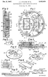
2432424
Electromagnetic sound translating device, John
J Hyland, William
J Muldoon, Control
Instrument Co, 1947-12-09, 381/418; 310/25 - |
|
2523775
Electromagnetic transducer, William J
Muldoon, Weeler
Insulated Wire, 1950-09-26, -
|
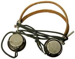
Chest Set
This set has a strong similarity to the Dynalec UA1814-1
(702020-110) NSN: 5975-01-27, DTID: 3211A0128BH21 but this
set has the chest mount microphone support and headphone
headbands.
In the movie Submarine: Steel Boats - Iron Men (IMDB)
about life on the USS Hyman G. Rickover (Wiki)
what appear to be sound powered chest sets are used in many
places.
Fig 1 United States Instrument Corp.
 |
|
Dynalec H-200/U Sound Powered
Chest Set
|
Type H-200/U
Sound Powered
Headset-Chestset
NSN: 5965-00-900-6401
Naval Sea Systems Command
Dynalec Corp p/n: 702019-375
Contr: DLA900-90-C-1582
Serial No. (blank)
Insp. (blank)
|
Patents
2149628
220566?
2205906
Sound translating device supporting assembly, Herbert
F Obergfell, Associated
Electric Labs,
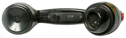
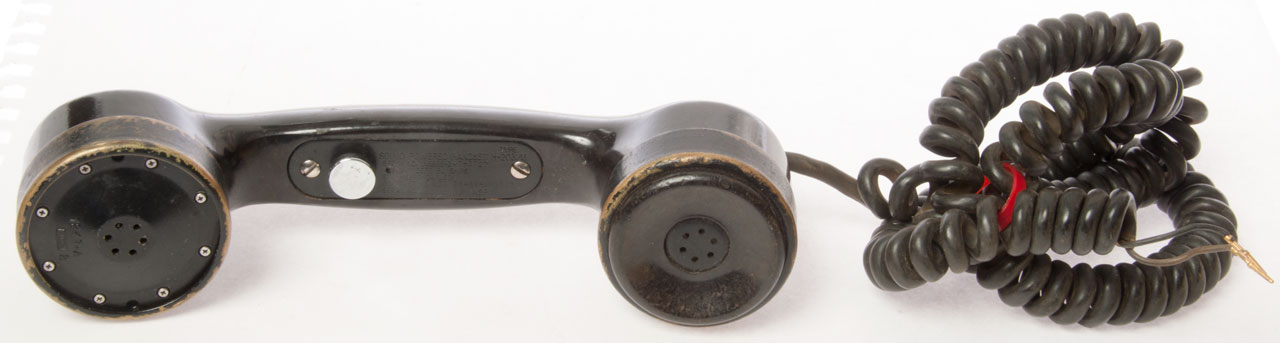
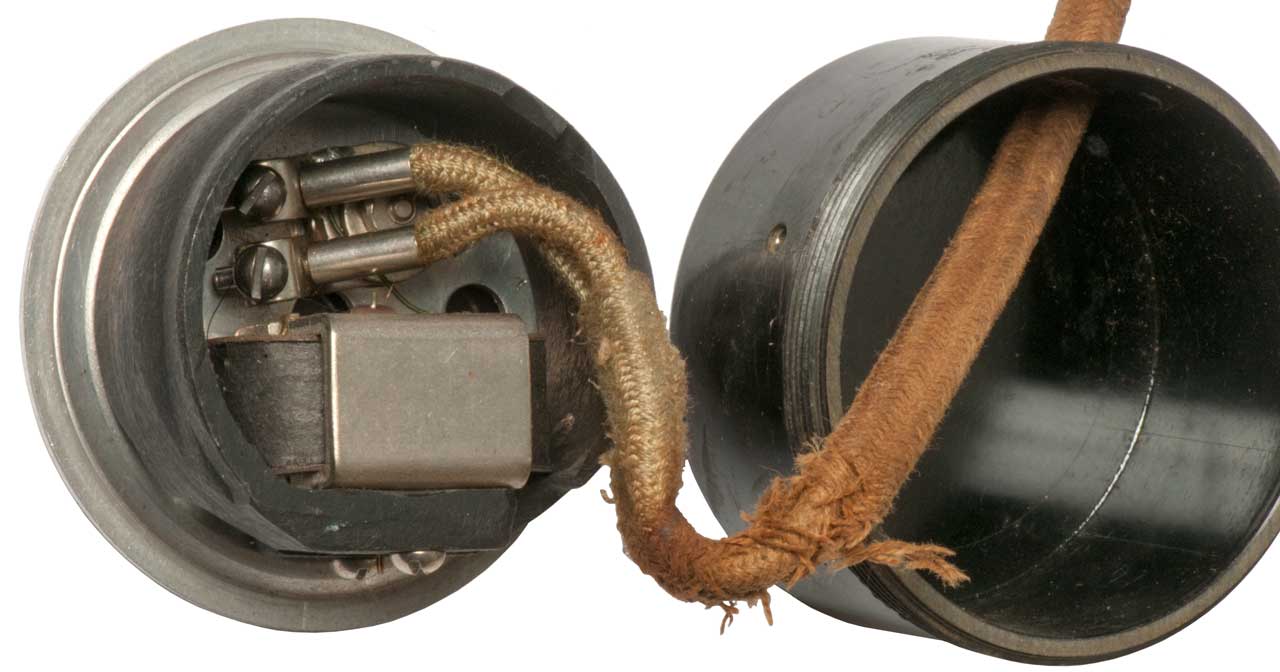
H-203/U Handset
This is a handset with Push-To-Talk button. With the
button up the resistance between the 2 leads shows open,
when the button is pressed the resistance is about 32
Ohms. In DMM Diode Test mode when the button is
pressed and the leads are brushed against the phone
terminals you can hear scratching sounds from both the mike
and earphone on the handset.
Switch Plate marked:
Sound Powered Handset Type H-203/U
Stock No. 1N5965-247-0727
Navy Dept. Bu. Ships
Stromberg-Carlson
Contract No. N001 26-69-G-2303
Serial No. (blank) Insp. (blank) |
Receiver Marked:
1247-A
Alcoa 2
|
Transmitter Marked:
1247-A
Alcoa 1
|
There is a small difference in the elements used for the
microphone and speaker, but the fundamental part numbers
seem to be the same.
Fig 1 The screw on caps are made of
brass, not plastic.
|
Fig 2
15 MF
200 VDC
|
|
1247A
Alcoa 2
UA1614-1
U.S. Patent
No. 2245511
9/67
|
1247-A
Alcoa 1
UA1614-1
U.S. Patent
No. 2245511
10/69
|
|
|
|
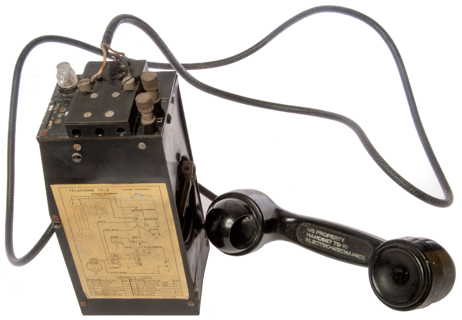
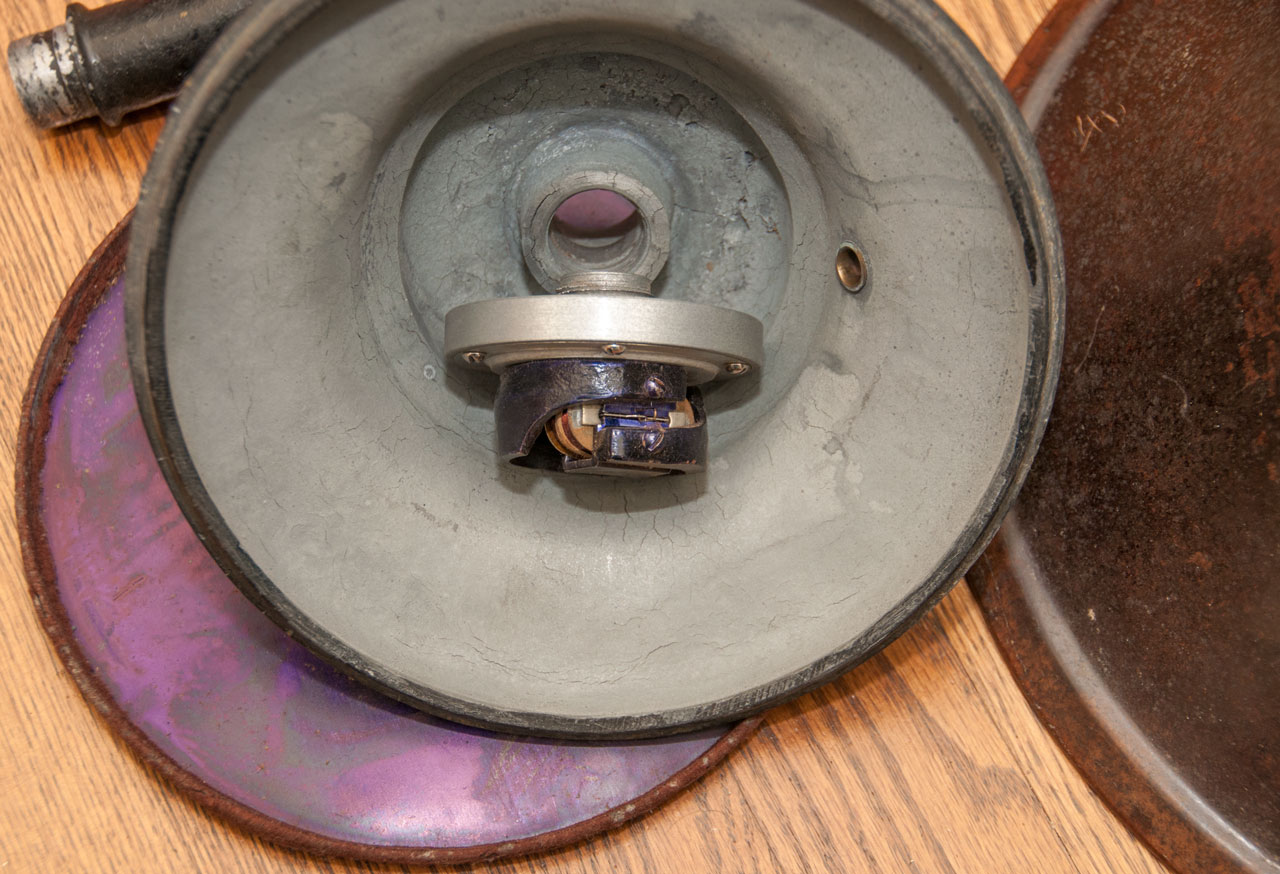
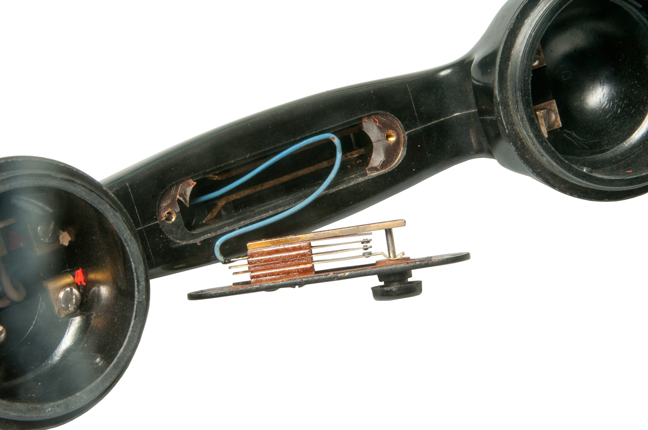
TP-3 Sound Powered Telephone Set
This is a telephone set, meaning that it has ringer
capability in addition to the sound powered aspect. It
has the same functionality as the TA-1
Sound powered field phone set below.
This is a derivative of the EE-8 Field
Telephone and uses the same outer case (either leather
or canvas) and many other parts interchange. The key
difference is that the handset makes use of sound powered
elements and so it does not need a battery. The sound
power elements are the same as in
the H-203 handset.
There are a couple of blocking capacitors included in this
set, one to keep DC out of the sound powered handset and
another to keep DC away from the ringer coils/core.
When used with a common battery switchboard an off hook
signal to the operator is possible by shorting the L1 and L2
terminals in an alternating pattern of 1 second short 1
second open.
Manuals
Instruction Book for Telephone TP-3-T1
December 5, 1938
Reprint July 15, 1940
TM11-2043
TO 16-40T-P3-5
Telephone
TP-3
War Department - 30 August 1944
Technical Data
The handsets measure 36 and 40 Ohms. About the same
as the H-203 above which makes sense since they both use the
same elements.
Fig 1

|
Fig 2 the right side plate is bent.
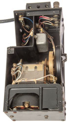 |
From Instruction Book.
This is the same mechanism
as 1767546 Fig 2 (below).
|
Fig 3
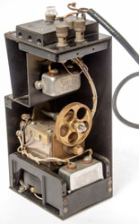 |
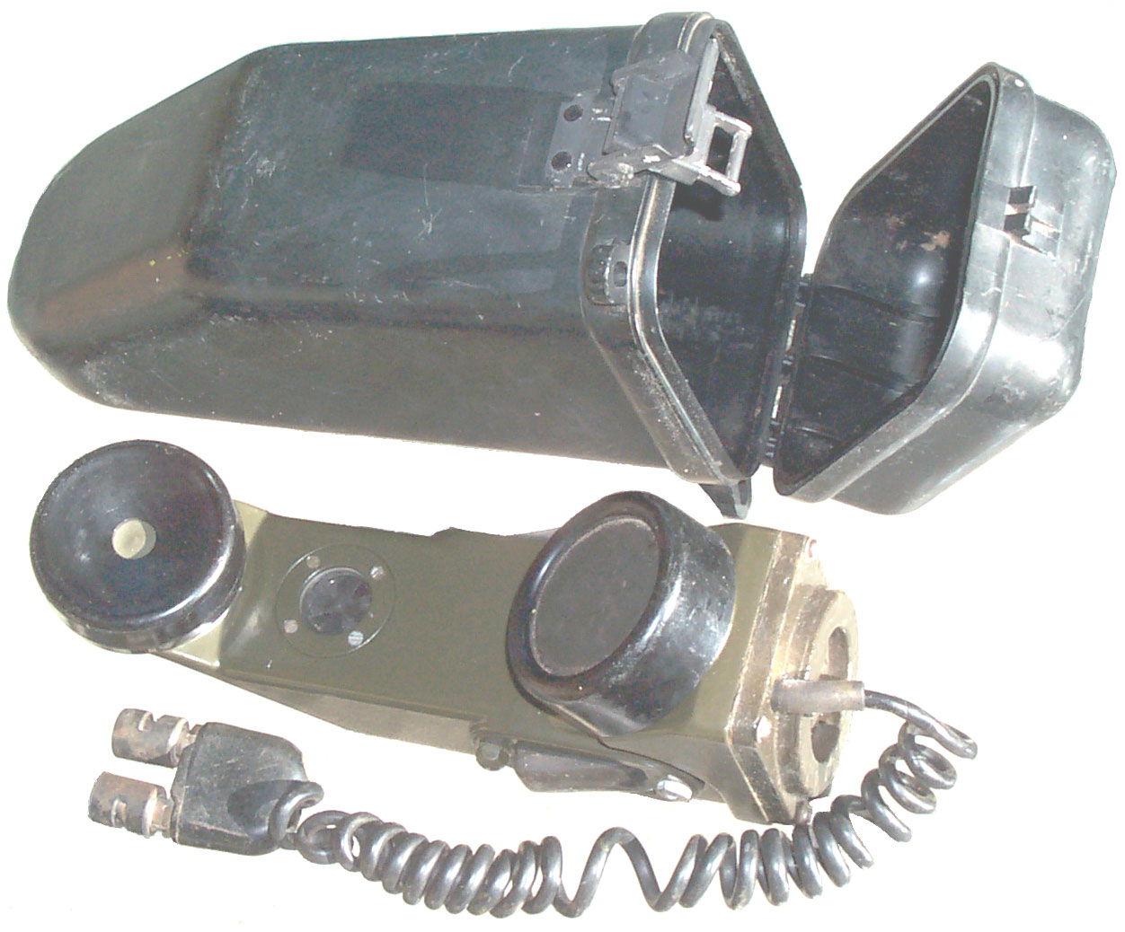
TA-1 Field Phones
Note the ear piece is much thinner on the TA-1 when
compared to the The chest set, H-203 or TP-3 above.
That's so that the ear piece can be placed under a helmet.
Fig 1 with carry case
|
Fig 2

|
Sound powered field phones with generator driven buzzer, so
no batteries or external power needed. On separate web
pages TA-1.
Earphone element: SM-D-189373
Microphone element: TA-Z21/PT
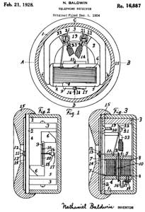
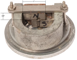
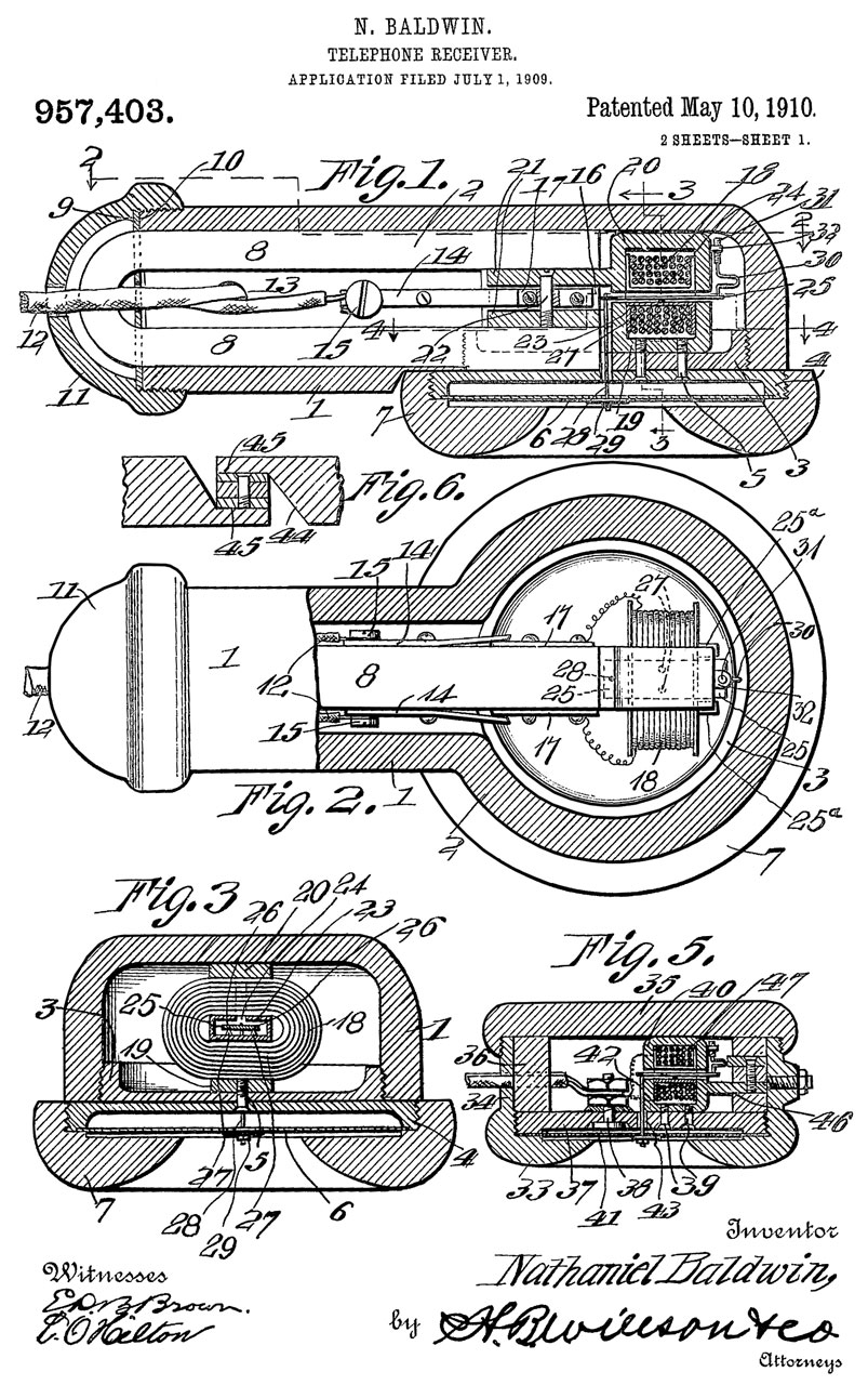
Baldwin Speaker
Driver
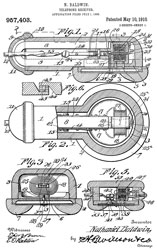
The 957403 patent dated May 10, 1910
appears to the the oldest on this web page and is for an
efficient sound powered microphone or earphone, but it's not
a loud speaker, i.e. there's no large cone. Note that
the term "speaker" was used in this time frame to mean
anything that made sound. So, for example a telephone
handset has a microphone and speaker. For loud
speakers see the Lektophone.
This earphone driver uses the efficient drive
mechanism where the coil axis is at right angles to the disk
center axis.
Markings shown in Fig 1:
Nathaniel Baldwin Incorporated
Salt Lake, Utah
Pat. May 10, 1910 - Oct 26, 1926
Nos. 957403 - 1604251
When I used a magnetic polarity tester to determine the
polarity of the horseshoe magnet the tester did not respond,
meaning that the magnet had lost it's charge. To
recharge it I used a stack of neodymium disk magnets to
recharge the horseshoe magnet. (see: K&J
Magnetics)
Both of the below patents show some support for the armature
on the end opposite the diaphragm drive rod. The newer
patent also shows the pole pieces that look very similar to
the photos, but the spring support on the end of the
armature opposite the drive rod is missing from this
example.
The end of the armature can be moved so is somehow floating.
I attempted to add modern 1/16" thick magnets to the poles
of the existing horseshoe and pole pieces, but it didn't
seem to offer much improvement over just using a modern
magnet to recharge the horseshoe magnet. Fig 3 &
Fig 4 were marked with measurements to help selecting
magnets.
https://patents.google.com/?q=H04R11%2f00&inventor=Baldwin&country=US&sort=old

|
905781
Telephone Receiver, N.
Baldwin, 1908-12-01, 381/418; 340/388.1; 335/231 -
|
|
957403
Telephone-receiver, Nathaniel
Baldwin, May 10, 1910, 381/418
-
|
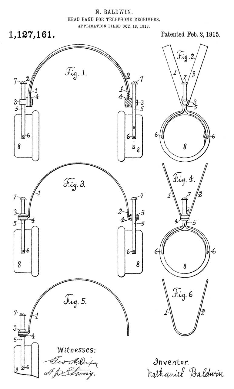
1127161
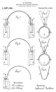 |
1127161
Head-band for telephone-receivers, Nathaniel
Baldwin, 1915-02-02, 381/379; D14/205 -
|
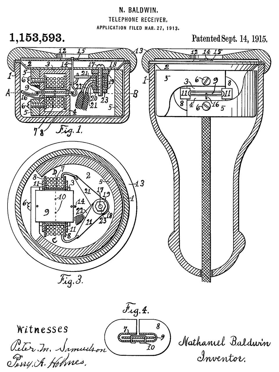
1153593

|
1153593
Telephone-receiver, Nathaniel
Baldwin, Sep 14, 1915, 381/418
-
|

|
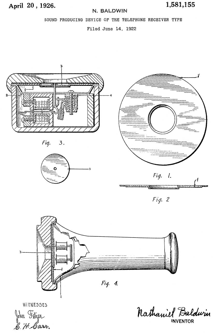
1581155
Sound-producing device of the telephone-receiver type,
Baldwin
Nathaniel, App: 1922-06-14, Pub: 1926-04-20, 381/386 -
|

|
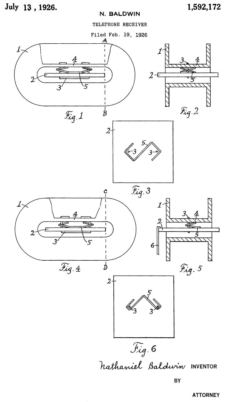
1592172
Telephone receiver, Baldwin
Nathaniel, 1926-07-13, 381/418; 335/270 -
|
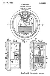 |
1604251
Telephone receiver, Nathaniel
Baldwin, Oct 26, 1926, 381/418, 381/419 -
3: horseshoe magnet
4 & 5: pole
pieces
9: flat plate armature
|
|
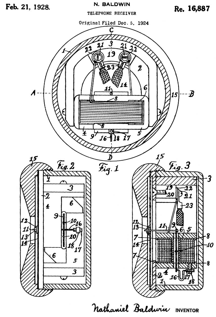
RE16887
Telephone Receiver, N. Baldwin, App: 1924-12-05, Pub:
1928-02-21, 381/418 -
This is a Re-Issue of 1604251.
|

|
1683945
Telephone receiver, Baldwin
Nathaniel, 1928-09-11, 381/418 -
based on patent 957403.
"... to provide a virtual fulcrum for the armature
within the spool."
|
|
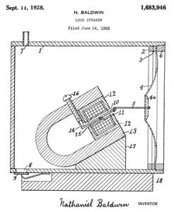
1683946
Loud speaker, Baldwin
Nathaniel, 1928-09-11, 381/162; 381/165; 381/417 -
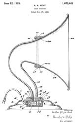
Paper cone diaphragm (4).
Hydrogen gas enters at port (7) , and flap valve (8
& 9) maintain a constant pressure inside the
cabinet.
|
Fig 1

|
Fig 2
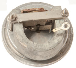 |
Fig 3
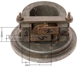 |
Fig 4
 |
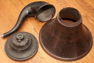
Baldwin
Driver + Horn
This is a three part horn.
The cast iron base holds the driver.
The cast iron neck connects the base to the big horn.
The big horn is made of Bakalite with a sheet metal ring for
the connection to the neck
Fig 1
|
Fig 2 Note bottom plate of base is
friction fit with felt trapped between the two.
 |
Fig 3 Using the DMM Diode test function
produces a loud scratching noise.
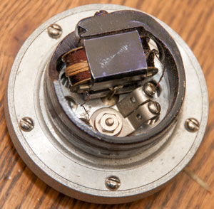 |
Fig 4 Nathaniel Baldwin Incorporated
Salt Lake City, Utah
Patented
May 10, 1910 Sept 14 1915
Those are different than the patents listed on the driver above.
They are 957403 and 1153593
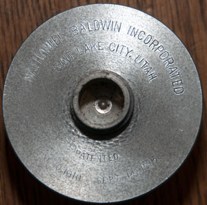 |
Fig 5
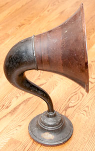 |
Fig 6 "Standard Loud Speaker"
 |
Baldwin Headphones
Label on back of phones:
Manufactured and Sold by the Baldwin Radio Co. Salt Lake
City, Utah, under Nathanel Baldwin's Pat May 18, 1910 (see 957403 above), Sept 14, 1915 (see 1153593
above), Type "C".
Note that patent 1604251 (See above)
is not referenced so these were made after 1915 and before
1924.
Fig 1
|
Fig 1cu Close Up of Label
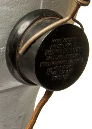
|
Fig 2 Pat Feb 2, 1915 (see 1127161 above)
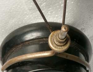 |
Fig 3 Inside
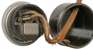 |
Fig 4 Inside
 |
|
Dictograph
Western Electric No. 555 Receiver
This was the first loudspeaker to be used for talking
movies (Wiki).
It consisted of the WE No. 555 moving coil driver coupled
with a huge horn to make enough sound for to fill a movie
theater.
1707544
Electrodynamic device, Albert L Thuras,
Western Electric, Filed: 1926-08-04, Pub: 1929-04-02 -
Dynamic moving coil speaker driver - WE No. 555
1729806
Electrodynamic device, Albert L Thuras,
Western Electric, Filed:1928-04-26, Pub: 1929-10-01 -
increase the efficiency of electrodynamic devices
1812389
Acoustic device, Edward C Wente,
Western Electric, Filed: 1925-04-01, Pub: 1931-06-30 -
probably the No. 555 driver "Receiver"
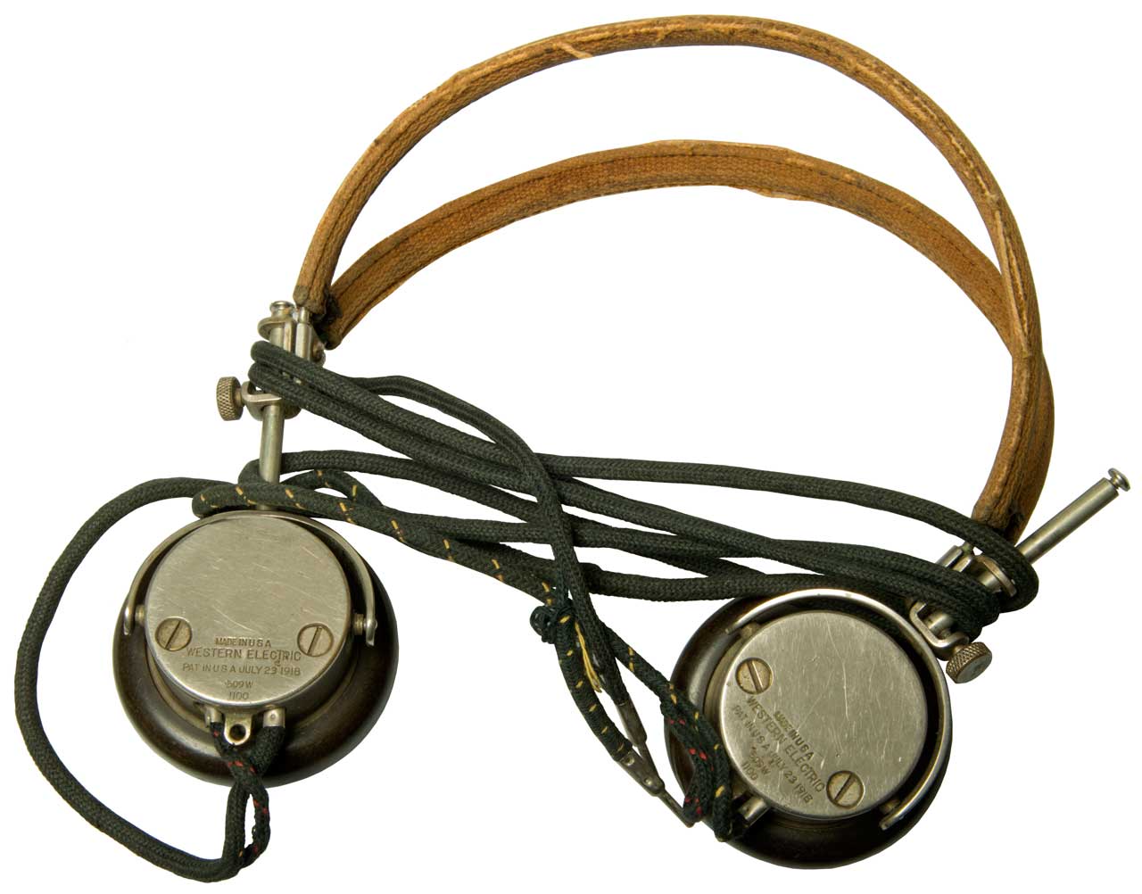
Western Electric No. 509w Receiver
These were designed to work with the 600 Ohm impedance
telephone system in the voice frequency range? But
measurements show they are over 100 times higher in
impedance at 1 kHz than 600 Ohms, so that idea may not be
correct?
Each earphone measures 1.1 k Ohm at DC and at the tip lead
measures 2.2 k Ohm (Fluke 87V DMM), i.e. the headphones are series
wired.
The DE-5000
measures 5 H inductance at the tips and 69 k Ohms both at 1
kHz.
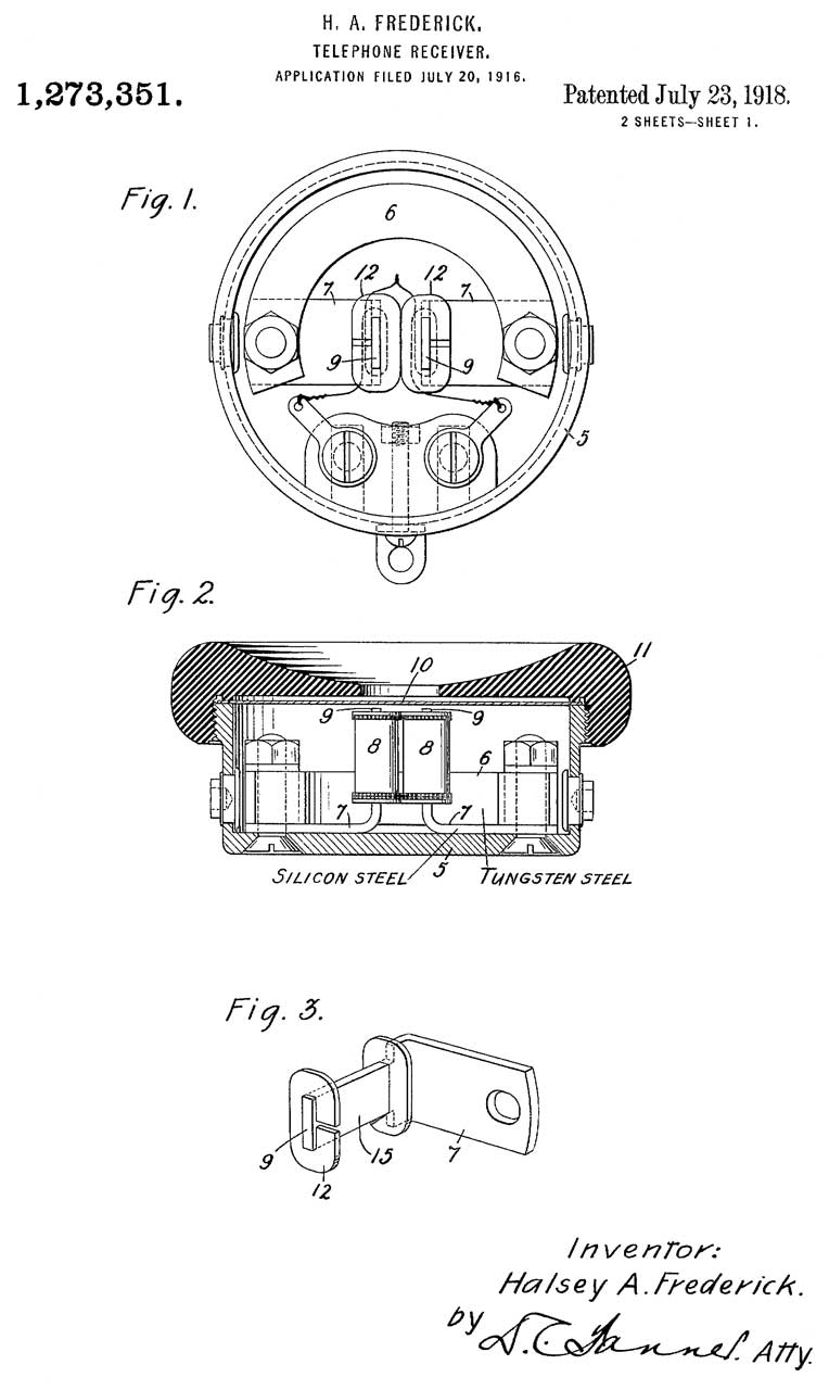
|
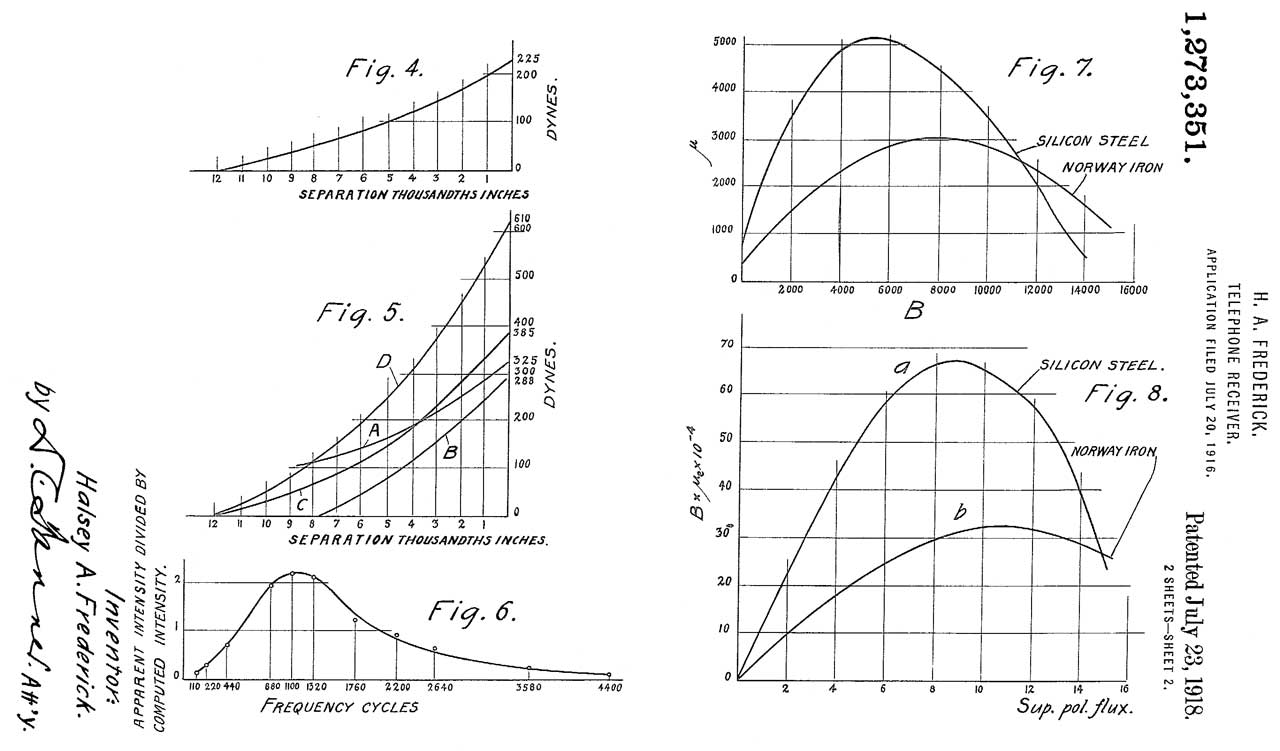
1273351
Telephone-receiver, Halsey
A Frederick, WE,
1918-07-23, - maximum efficiency (for the time), uses
Silicon steel coil core.
This shows the change over from soft iron to Silicon
Steel for electromagnets.
Fig 4. Diaphragm stiffness due to the cap.
Fig 5. Force, deflection and magnetic attraction for
this receiver
Fig 6. Composite curve of the apparent variation in
sensitiveness of the human ear
Fig 7. Permeability of Silicon Steel and Norway iron
v. flux density
Fig 8 Flux density comparison Silicon steel v. Norway
iron
|
Fig 1
|
Marked:
Made in U.S.A.
Western Electric
Pat in USA July 23 1918
509W
1100
|
|
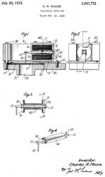
1547772
Telephone receiver, Charles
R Moore, Western
Electric, 1925-07-28, - sound power type, i.e.
right angle receiver
also see WE 396A Chest horn
Carbon microphone
|
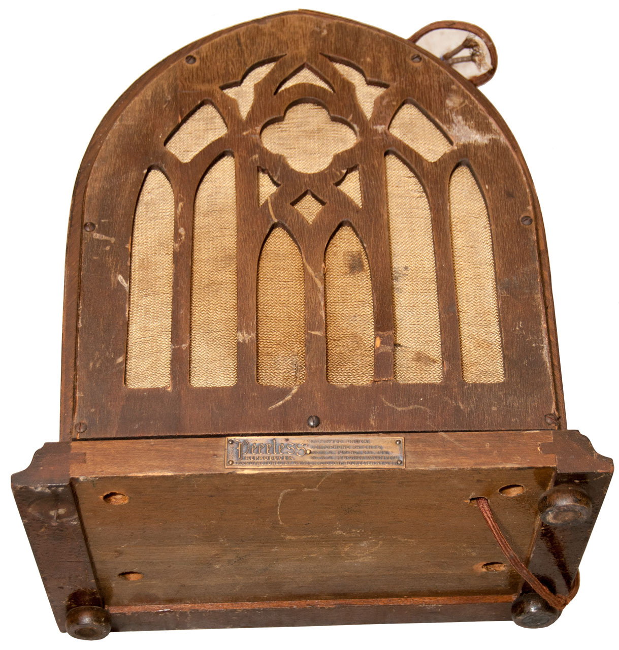
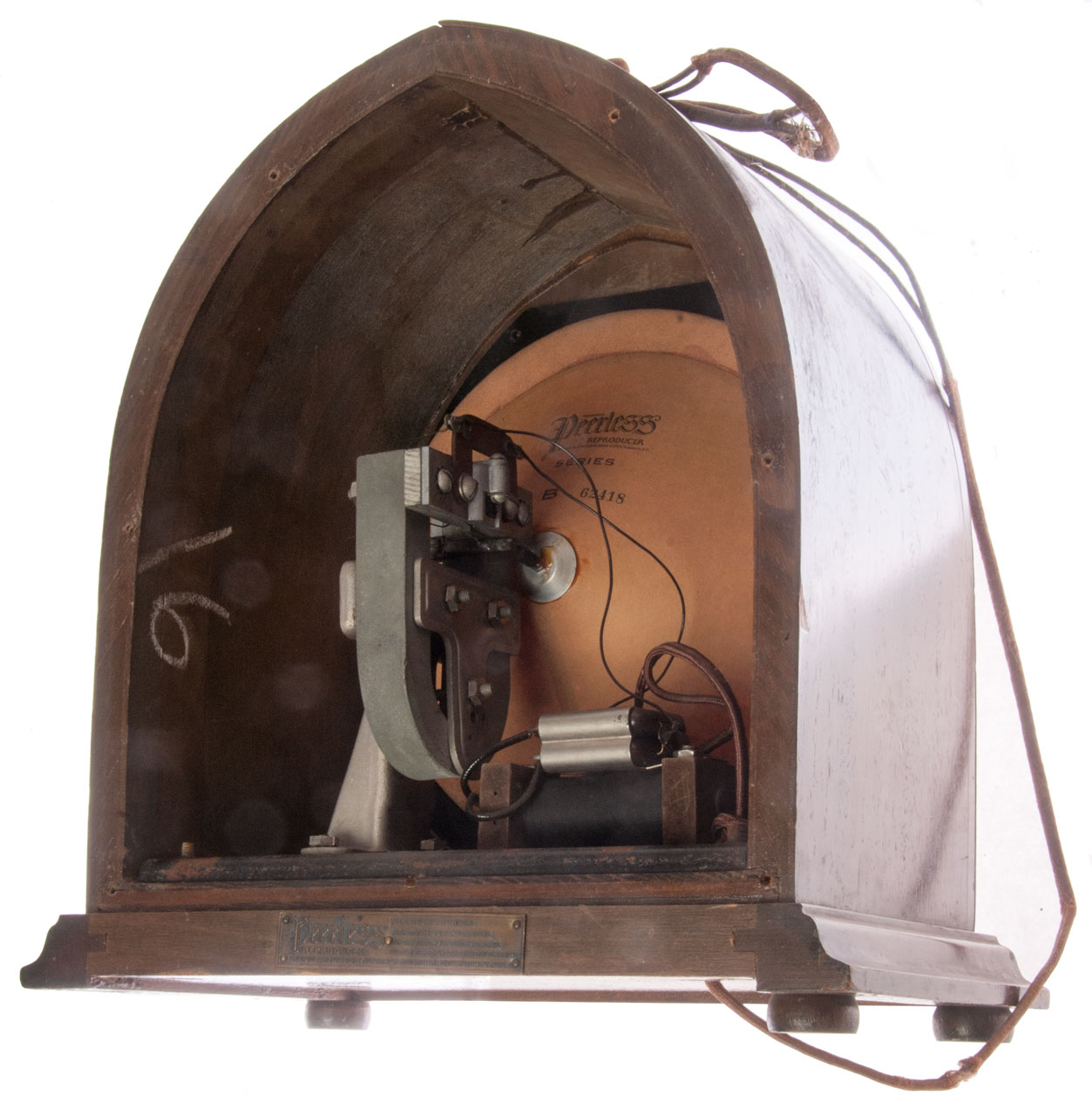
Peerless Speaker (Lektophone)
This speaker was made under the
Lektophone Patents as were many early speakers while the
patents were in force.
The label spells this out.
Peerless
Licensed Under
Lektophone Patents
No. 1271527 - No. 1271529
No. 1271528 - Other Patents Pend.
Manufactured by United Radio
Corp. Rochester, N.Y. U.S.A. |
This speaker was purchased and
it's located on the Sound Powered Telephone web page
because the central axis of the coil is a right angles to
the central axis of the speaker cone, i.e. an efficient
structure.
The speaker measures 1.34 k
Ohms. There is a low pass filter made up of two
capacitors and an iron core inductor between the input
wires and the speaker proper. When you look into the
front with a flashlight you can see a second cone.
That's to say there are two speaker cones with different
cone angles.
Photos
Fig 1 Front
|
Fig 2 Back
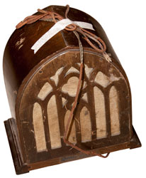 |
Fig 3 Bottom
 |
Fig 4
 |
Fig 5
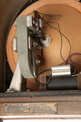 |
Fig 6 Coil at top of horseshoe magnet
has it's axis up and down.
 |
Patents
----------------------------
Listed on Label ----------------------
1271527
Sound-regenerating machine, Marcus
C Hopkins, Lektophone
Corp, Jul 2, 1918, 369/80,
369/158
- This is a
flat record player (not Edison cylinder, Wiki)
and instead of using a horn speaker (Wiki)
it uses a large diameter cone that has a rod driving the
center point.
1271528
Sound-regenerating machine, Marcus
C Hopkins, Lektophone
Corp, Jul 2, 1918, 369/158,
369/170
- very similar to the ...527 patent.
1271529
Acoustic device, Marcus
C Hopkins, Lektophone
Corp, Jul 2, 1918, 181/164,
181/173,
181/171,
369/155,
381/432
-
-------------------------- Other Patents Pend.
----------------------
1389632
Acoustic diaphragm, Davis
William H, Joss
Fredrick E, Lektophone
Corp, Sep 6, 1921, 181/171
- Just the
cone part of a speaker
1829355
Acoustic diaphragm, Houghton
Vernon T, Lektophone
Corp, Oct 27, 1931, 181/173
- about folding the cone outer diameter
surface to add compliance. Modern speaker cones have
"ripples" to to that.
1855168
Loud
speaker, Farrand
Clair L, Lektophone
Corp, Apr 19, 1932, 381/418,
381/432,
181/172
- can
be used as either Microphone or speaker. "'The principal object of this
invention is to provide a loudspeaker of the above
described general type in which the flexible support for
the diaphragm is supplemented by a special flexible
support for the armature, which will permit the armature
to move freely in an axial direction but will hold the
armature, or assist the flexible support for the cone in
holding it, in the proper aligned position in the air gap.
" Coil axis is concentric with cone axis so not the
high efficiency Sound Powered Telephone design.
Lektophone Corporation v. The Rola Company, 282 U.S. 168
(1930) (Supreme.justia,
FindLaw)
"There is not to be found in the prior art a
sounding board such as Hopkins designed and had patented
as his invention, and it is not enough to defeat his
patent to say that the elements of his claims are already
found in the prior art in isolation or in other
combinations."
963362
Apparatus for recording or
reproducing sounds, Thomas
A Edison, Jul 5, 1910, 369/165;
181/162; 181/173; 369/168 -flat pleated disk, not a cone
986477
Acoustical instrument, Louis
Lumiere, Mar 14, 1911, 29/896.23;
369/160 - pleated cone
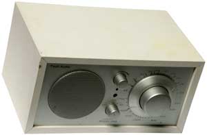
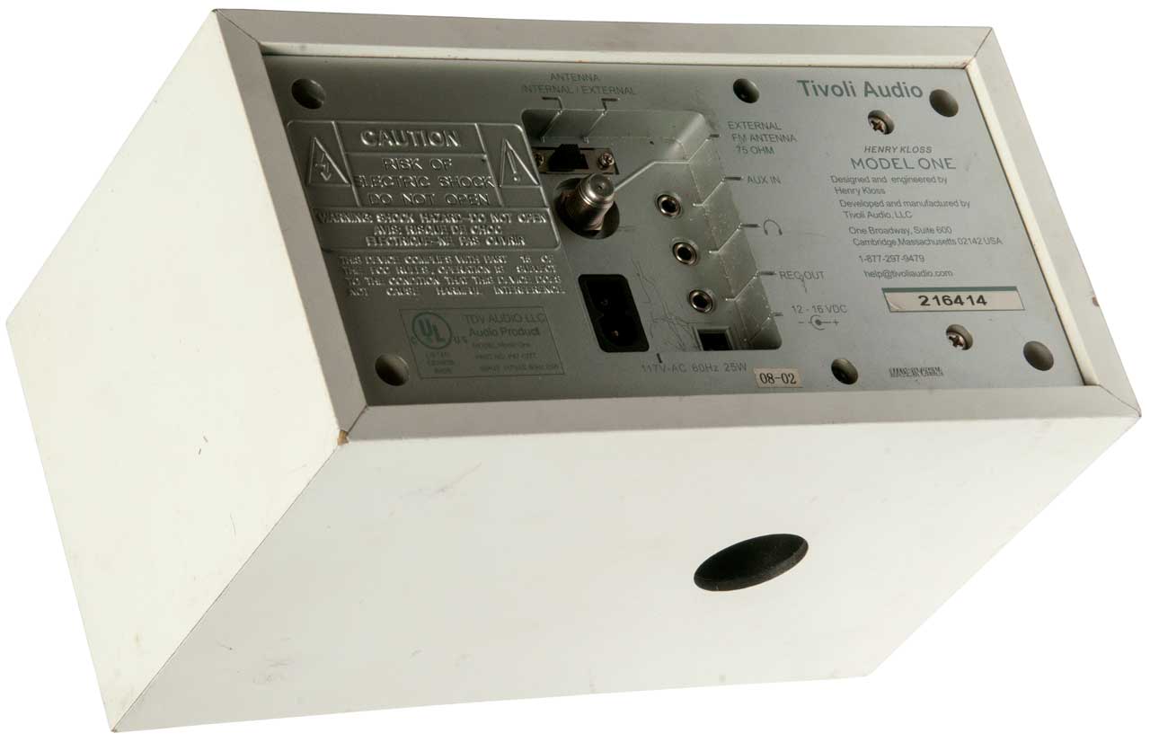
Tivoli Audio Model One Radio
Tivoli Audio (Wiki)
- "The Company was founded in Massachusetts in 2000
by legendary audio engineer Henry Kloss and entrepreneur Tom
DeVesto, who noticed a gap in the consumer audio market for
high-quality, well designed and affordable audio products.
Their first product was the Model One, a simple to use
mid-century modern designed table top radio with a
high-performance tuner, receiving FM radio in congested urban
locations, while maintaining the ability to pick out distant
or low power stations."
The
Strange Truth about KLH, Advent, Acoustic Research,
13:03 -
While watching a number of streaming TV series set in
Scandinavian countries a common small table radio shows up.
I searched for it expecting it to come from Sweden or
Denmark. But it was designed in the U.S.A. and some
legendary audio people were involved.
While the design was what attracted me in the first place
there are other features that make this even more
attractive. The Auxiliary input senses when the 1/8"
stereo plug is inserted and turns off the radio audio
automatically. This allows the box to be used as an
amplified speaker. See: Music Speakers. In
addition there is an option for "12 Volt DC" power, which
has two advantages, first: allows radio to be used in an
emergency powered from batteries or a cigarette lighter
adapter and second: by using a small battery as a portable
music speaker.
It came with only the AC line cord, so I purchased an FM
antenna with a Type-F connector on eBay as well as some
stick-on feet since the factory feet had fallen off.
While researching this model I found a number of fix-it
YouTube videos about replacing the tuning capacitor.
Rather than do that I looked for a radio that had a
manufacturing date sticker hoping that meant the radio was
new enough not to need that repair. So far that's the
case.
Photos
Fig 1
|
Fig 2 The black circle is the end
of a tube
that's part of the bass reflex loading design.
 |
Fig 3 Connectors
Aux In: 1/8" stereo
DC In: 5.5mm x
Ant: The eBay "75 Ohm
Indoor FM Dipole Antenna Radio Stereo Signal
Receiver Amplifier Aerial" is defective.
Instead of a wire center conductor it has a tube so
will not fit. I have a message to the seller:
lepo-beauty. More after
I hear back.
This is a "PAL" connector for Eurpoe, not the wire
type for the US.

|
Bass Reflex Speaker Design (Audio
Judgement)
YouTube: Tivoli Audio Model One
Radio, 20:51 - her radio may have problems. Also
she connected an AM antenna to the FM antenna jack.
CCRadio2
This radio is made at C Crane located a few hours
drive North of me. It has bands: FM, AM, 2 meter Ham, WX
& Aux audio in. It does not have shortwave.
Runs on AC line or internal 6 D cell batteries. This is
much more convenient than using an external battery pack with
the Tivoli above. After a month or so the "D" batteries
have gone dead. Not sure if that's because they started
out low or if the radio consumes a lot of power when
"off". You should probably store batteries out of the
radio.
When the batteries die so do all the presets.
Not so great as an emergency radio because there will be no
preset frequencies. You need a hard copy so you can load
the frequencies after you install fresh batteries.
There are 5 preset frequencies for each band so a total of
20. To select a preset you need to first choose the band
then press the desired preset.
There have been a number of CCRadios with different features
over the years. Got this one used from eBay. It's
the CCRadio2 not the CCRadio2E that has better sound quality.
Preset frequencies:
1. (2 meters) 147.39
Press and hold a control for a few seconds to get the
(secondary function).
Main Tuning knob (Squelch)
Unlike the Tivoli
above, this radio does not have an external FM antenna
input.
Power
AC mains or internal 4 internal D cell batteries.
Mode
|
VDC
|
Function
|
Current
ma
|
Off
|
6.0
|
BL Off
|
0.001
|
Off
|
6.0
|
BL Very Dim
|
0.000
|
Off
|
6.0
|
BL Bright
|
0.017
|
On
|
6.0
|
Loud
|
0.3
|
| Dead |
3.9 |
-- |
-- |
The Energizer L95 (datasheet.pdf)
should last a very long time IF the Back Light (BL) is off
or very dim AND the WX monitor function is turned off.
Note: When the battery goes dead you loose all preset
frequencies.
Fig 1 Front

|
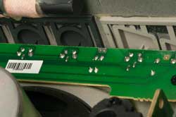
Fig 4 Close-up of top Push Button PCB.
Right Angle Momentary Tactile Push Button Switch
maybe 6x6x5mm size?
The buttons are hinged and
have a post that presses on the switch.
There are Surface Mount resistors, maybe the
resistance
indicates which button pressed, or it's a matrix?
|
Fig 2 Rear
 |
|
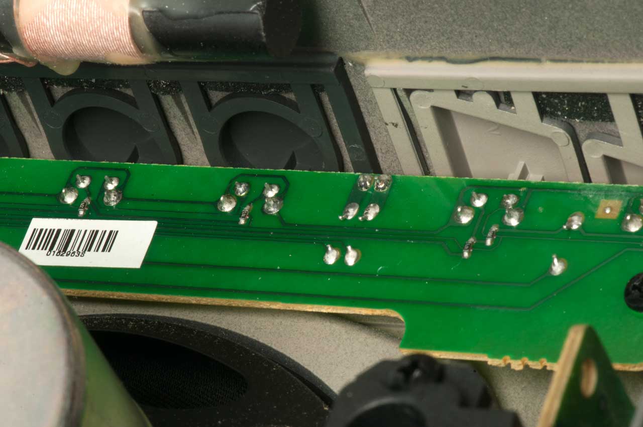
Fig 3 Inside - Looks like was in dusty
environment.
 |
Remove 6 screws (all have an arrow).
Top: Ferrite Antenna
8 Push button PCB
Left: RF & AF PCB..
Left hidden: Front panel PCB
Middle: 4 Ohm 6 Watt Speaker
AC to 6VDC power supply at lower right corner.
|
Acoustic Research Speakers
Acoustic Research (Wiki) - "Acoustic Research, Inc. (“AR”)
was founded in 1952[1] and incorporated on August
10, 1954, by audio pioneer, writer, inventor,
researcher and audio-electronics teacher Edgar Villchur and
his student, Henry
Kloss."
When I built a Heathkit Hi-Fi system the speakers were
copies of the AR-1.
YouTube: DeVORE FIDELITY: John
DeVore goes on a rant about the High End Audio lie that
inspired him to start his company - This is about
speaker sensitivity.
The
Strange Truth about KLH, Advent, Acoustic Research,
13:03 -
|
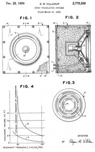
2775309
Sound translating devices, Edgar
M Villchur, ACOUSTIC
RES, 1956-12-25, 381/346; 181/151 -acoustic
suspension
Kloss was taught by Villchur at NYU
|
|
3150441
Method of making a loudspeaker, Henry
E Kloss, KLH
Research and Development Corp, 1964-09-29, -
|
|
5046104
Loudspeaker system, Kenry
E. Kloss, Cambridge
Soundworks, 1991-09-03, -
|
YouTube: The
Truth about Speaker Size Nobody Talks About, 21:40 -
UK LS3/5A speaker (Wiki); Q Acoustics:
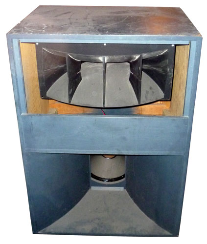
A7 Voice of
the Theater Speakers
Altec Lansing (Wiki),
JBL (Wiki)
I got these as part of a Hi-Fi system that was built into a
house. There were alcoves on either side of the
fireplace where these sat. A speaker cloth grill
covered them and the wiring was routed inside the house to
the electronics which ended up being McIntosh. See Home Theater VOT for
more.
The sensitivity of the A7 VOT is 97 dB. (sound level 1
meter in front of speaker with 1 Watt drive.) This
goes directly to dynamic range since the maximum power is
limited to the 200 Watt speaker rating or the amplifier
rating. When music is played loud you're at the max
rating for the loud passages and the speaker sensitivity for
the quieter passages.
The heart of the speaker is the horn (Wiki).
A comment by James Wilkes related by my comment on the
YouTube:
YouTube: DeVORE FIDELITY: John DeVore goes on a
rant about the High End Audio lie that inspired him to start
his company - This is about speaker sensitivity:
Looks like they have a
515B LF driver, Altec Lansing specs for it say 98dB at 4'
with 1W pink noise 500-1000 Hz, which is probably the safe
figure -
500-3000 Hz yields 102 dB, but that's because the driver is
rather peaky above 1000 Hz. SPL varies with distance per
square law,
so a reading from 1m should be nearly 2 dB higher,
approaching 100 dB/1W/1m. Very efficient speaker.
Time Alignment (Wiki)
This may be the reason that the voice coils of the horn
and speaker are in the same vertical plane. Another
reason may be to make the horizontal pattern the same for
the horn and speaker. Both of these would tend to
make the sound better over a larger area than not doing
it.
The web page on time alignment (http://www.troelsgravesen.dk/Time-Alignment.htm)
shows a case where the frequency range is about 1600 to
4000 Hz and so may not be applicable to the VOT speaker
where the crossover frequency is around 900 Hz and where
the physical difference is voice coil locations would
differ by almost two feet.
|
|
|
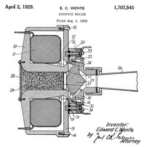
1707545
Acoustic device, Edward
C Wente, Bell Labs, 1929-04-02, 181/159 - Horn
speaker/microphone |

|
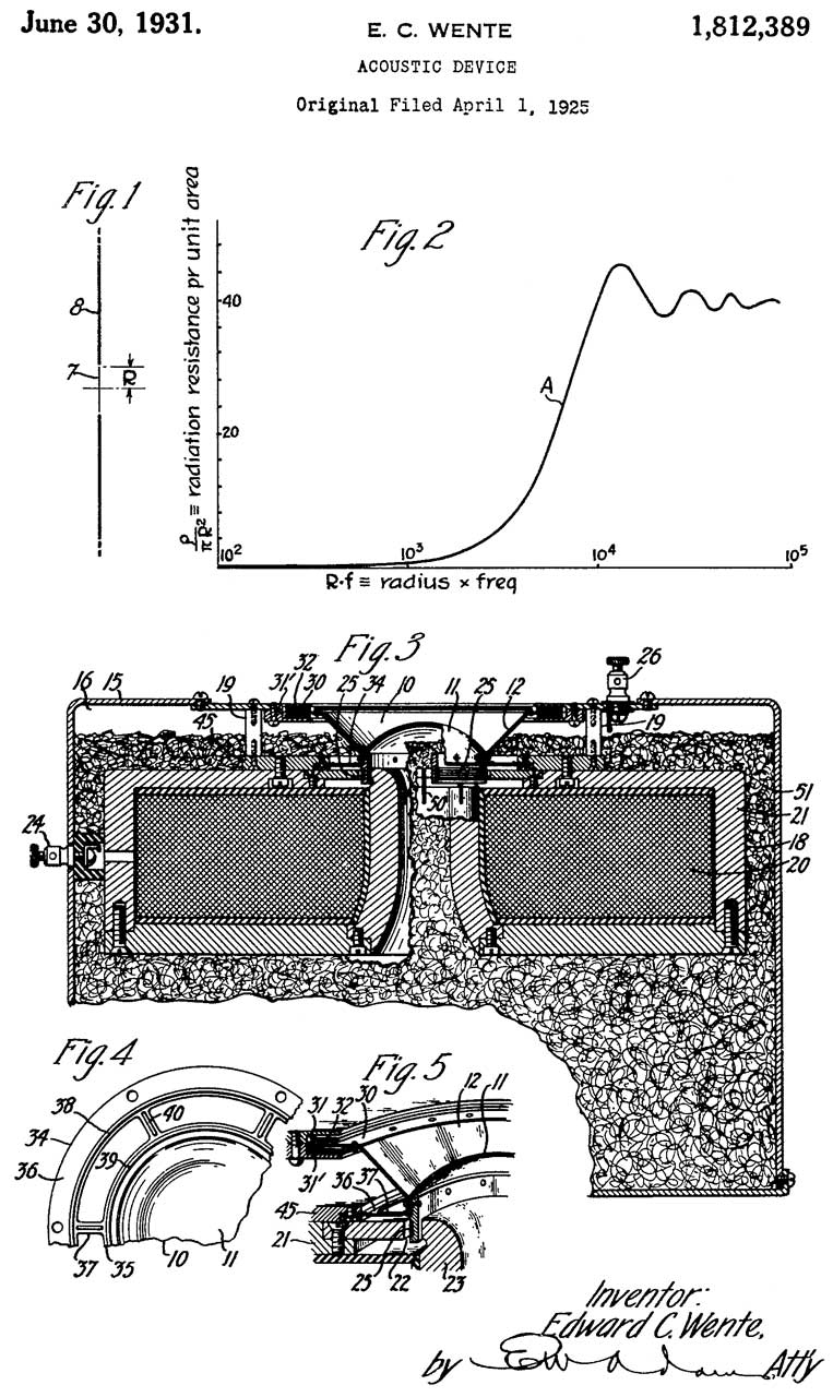
1812389
Acoustic device, Edward
C Wente, Western
Electric, 1931-06-30, 381/346 - direct-radiator
loudspeaker |
|
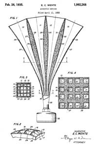
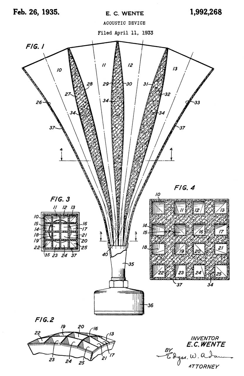
1992268
Acoustic device, Edward
C Wente, Bell Labs, 1935-02-26, 181/187 -
sectional horn
|
Freed-Eismann
Radio Speaker FE-50
See my Crystal Radio
page for information on this exponential horn speaker.
Like the VOT above it's very efficient.
Kellog S&S Co 178-C Chest
Microphone, 65A Earphone & 102 Four Prong Plug
Got this because it looked correct for the Western
Electric SCR-59 Three Tube Radio.
But the plug has the wrong diameter pins and the pin-to-pin
spacing is wrong.
|
|
|
986606
Telephone-body support, Victorien
Tardieu, 1911-03-14, - |
|
1567105
Head receiver set, Ernest
A Bohlman, Kellogg
Switchboard and Supply Co, 1925-12-29, -
|
|
1592978
Head receiver set, Jr
Frank William Kaisling, Kellogg
Switchboard and Supply Co, 1926-07-20, -
|
|
1598042
Head receiver set, Ernest
A Bohlman, Kellogg
Switchboard and Supply Co, 1926-08-31, -
|
|
1602517
Head receiver set, Frank
A Bosh, Kellogg
Switchboard and Supply Co, 1926-10-12, -
|
|
1657145
Receiver, Ernest
A Bohlman, Kellogg
Switchboard and Supply Co, 1928-01-24, -
|
|
1661082
Receiver,
Emil J Nielsen, Kellogg
Switchboard and Supply Co, 1928-02-28, -
|
|
1677185
Receiver, Kaisling
William, Kellogg
Switchboard and Supply Co, 1928-07-17, -
|
|
1943425
Diaphragm, George
R Eaton, Kellogg
Switchboard and Supply Co, 1934-01-16, - has
resonant frequency above audio range.
|
|
2014427
Microphone, George
R Eaton, Kellogg
Switchboard and Supply Co, 1935-09-17, - capsule
held together by two screws
|
|
2340777
Throat microphone, Harvey
H Stanley, Kellogg
Switchboard and Supply Co, 1944-02-01, -
|
Patents
Electric
Phonograph Pickup Patent
Prior to the early 1920s all the reproducers were
mechanical in nature because vacuum tubes (Wiki)
were not yet available.
1384295
Electric reproducer for
phonographs, Pierre
Frely Henry Armagnat An (Paris, France), Jul
12, 1921, 369/148
- prior to this all pickups and reproducers were mechanical.
1531252
Electrical reproducer for
phonograph records, Thomas
Jones Edward, Wired
Radio Inc, Mar 24, 1925, 369/147
- electrical pickup, 2 tube amp, driver & Horn.
Spring motor for phonograph disk.
1536116
Sound
reproducer, Martin
William H, American
Telephone & Telegraph, May 5, 1925, 381/184,
381/432
- Fig 2 efficient design driving
diaphragm attached to cone, horseshoe
magnet
1596045
Sound reproducer, Frank
J Kaehni, William
L Kaehni, Cleveland
Trust Co, Aug 17, 1926, 369/9,
123/73.00V
- driver moves flat diaphragm attached to dish shaped cone,
i.e. driving the wrong part.
1734271
Conical-diaphragm
sound reproducer, Peterson
Charles W, Nov 5, 1929, 181/166
-
Exponential
Folded Horn
2338262
Acoustic
horn, Vincent
Salmon, Jensen
Radio Mfg Company, Jan 4, 1944, 181/192,
181/194
-
cited by 4176731
Altec Corp. dual exponential horn. See Voice of the Theater)
Sound Powered
Elements
All of the below patents use the same type of element where
a rod couples the diaphragm to the permanent magnet device.
|
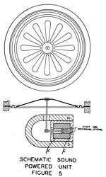
1767546
Sound-reproducing
device, Mueller
Herman C, Jun 24, 1930, 381/418, 381/419 - this
is a loudspeaker consisting of an exponential horn
connected to a removable "driver". The driver
contains a horseshoe magnet.
This is very similar in function to the Freed-Eismann
Radio Speaker FE-50 and the Baldwin + Horn
above. These speakers needed to be very
efficient since they were powered from crystal radios
with very low output power. Note that a speaker
of this type can also be used as a microphone.
This patent is cited as prior art by the Roanwell patent
3454912 below.
|
1886031
Mechanical
construction of loud speakers, Langley
Ralph H, Crosley
Radio Corp, Nov 1, 1932, 335/231, 335/281, 335/266, 335/270 -
2267808
Electromagnetic
device, Nelson
Blount, Bell
Telephone Labor Inc, Dec 30, 1941, 335/231, 381/354 - ..improve the
efficiency and operating
characteristics....
|
2391627
Transducer,
Howell
Arthur S, Stromberg
Carlson Co, Dec 25,
1945, 381/418 - "A telephone of
this type is adapted to serve either
as a transmitter or receiver thus when
two of such, telephones have their
respective terminals connected by
suitable conductors in an electrical
circuit, the arrangement comprises a
complete telephone system which
operates without an external source of
current or power other than the sound
from the speakers voice. Such a
soundpowered telephone is especially
useful for military purposes and
therefore it must be small in size so
that it can be used in conjunction
with a helmet and its construction
must be such that it will not
bedamaged when overloaded by loud
blasts."
|
2603724
Sound
translating device arranged to eliminate extraneous
sound, Kettler
Alfred H, Rca
Corp, Filed: Oct 30, 1948, Pub:
Jul 15, 1952, 381/372, 381/359, 181/129, D14/249 - a noise
cancelling headsest. Needed because
headphones act as microphones when not on a
head. They add noise into a multistation
sound powered phone system. Switches are
not good in a emergency situation.
2611035
Noise-canceling
microphone, Duncan
Robert K, Rca
Corp, Sep 16, 1952, 381/94.9, 381/170, 381/115, 381/91, 381/94.7 - two
microphones back to back "noise-cancelling
close-talking"
2714134
Headset
receiver, Kettler
Alfred H, Touger
Martin L, Secretary of the
Air Force, Filed: Feb
27, 1951, Pub: Jul 26,
1955, 381/345, 381/371 - designed to work from sea
level to 40,000 feet.

|
2896026
Sound powered phone,
Kettler
Alfred H, Secretary of the Navy, Filed: Nov 2, 1953, Pub: Jul 21, 1959, 381/177, 381/337, 381/355 - This is about
adding an effective noise cancelling
capability to a sound powered phone for use on
ships during wartime conditions.
|
3111563
Electro-mechanical
transducer, Elmer
V Carlson, Industrial
Research Products Inc, Nov 19, 1963,
381/418, 335/231 - external magnetic
flux changes have no effect on output, i.e. shielded.
3454912
Transducer drive rod, Morrison
Louis A, Roanwell
Corp, Jul 8, 1969, 335/231, 381/412, 381/396 - headband holds two receivers,
adjustable height of each receiver
Murdock Headphones
These may not belong on the sound powered telephone
web page, but I've found some patents and his is where I'm
parking them.
655726
Telephone-receiver, William J Murdock, 1900-08-14, 381/393 - long pole or headphone style
786588
Telephone-receiver, William J Murdock, 1905-04-04, 379/428.01 - long pole
801034
Telephone-receiver, William J Murdock, 1905-10-03, 379/440 - long pole
853186
Telephone, William J Murdock, 1907-05-07, 379/428.01 - long pole case molded with woven
core
1091528
Circuit-detector, William J Murdock, 1914-03-31, 324/555 - headset with series battery and test
probes = audible continuity tester (test equipment, not phone)
1513924
Telephone head set, William J Murdock, 1924-11-04 - similar to
1583088 except pinch screw height adjustment
1583088
Telephone head set, William J Murdock, 1926-05-04 - headband
& two earphones, spring clip earphone height adjustment
Brandes Inc
1447969
Telephone head set, Dietrich Frederick,
Brandes Inc, 1923-03-13, 379/430; 296/139 - adjustable headband, see YouTube
1536482
Telephone receiver, Dietrich Frederick, Brandes Inc,
1925-05-05, 381/412 - matches design in
YouTube video. - specifically mentions ability to take apart
without breaking leads, but in video all the leads were
broken.
1543325
Headband for telephone head sets, Dietrich Frederick,
Brandes Inc, 1925-06-23, 2/209.3;
381/376 - to fit head of wearer
1544136
Electrical connection for telephone headsets, Dietrich Frederick, Brandes
Inc, 1925-06-30, 381/379;
174/36; 381/189; 381/377 - not exposed terminals so B+
from tube radio will not cause electrical shock.
1645231
Electromagnetic sound reproducer,
Dietrich Frederick, Brandes Inc, 1927-10-11,
381/160; 381/432 - triangular speaker enclosure
D71138
Loud Speaker, Dietrich
Frederick, Brandes Inc, Sep 28, 1926, D14/211 -
Condenser Microphone
1333744
Telephone-transmitter, Edward
C Wente, WE,
1920-03-16, -
Throat Microphone
I've read that these always sounded garbled and so were not
used for very long.
2121778
Sound translating
apparatus, Ballantine
Stuart, 1938-06-28 -
2121779
Sound translating apparatus, Ballantine
Stuart, 1938-06-28, - cited
by 25 patents
2121780
Sound translating
apparatus, Ballantine
Stuart, 1938-06-28, -
2121781
Sound translating device, Ballantine
Stuart, 1938-06-28, -
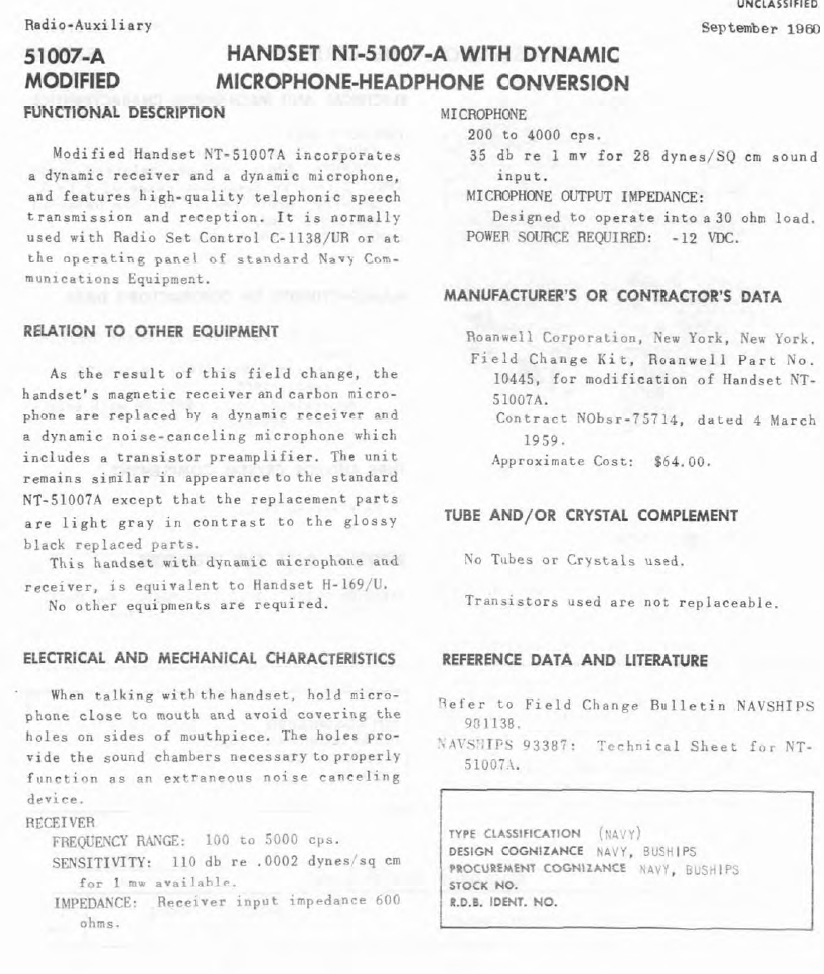
This NT-51007A (NSN: 5965-665-3480) is NOT a sound powered
unit, but rather a carbon microphone type.
Patents
Related to the 51007-A handset. The 51007 has a
carbon mike element. A retrofit kit (Navy-Radio: Xmtr-handsets,
NT-51007a)
replaced the mike and speaker with new elements giving the
51007A a dynamic mike with built-in amplifier and circuitry
that allows it to work with equipment that expects to see a
carbon mike element.
Roanwell still
makes the Type 503 H-169/U handset which is
based on an upgrade kit to the 51007 replacing the carbon
mike element with a dynamic element that contains an
amplifier designed to run from the carbon mike DC
bias. This mick element is a noise cancelling design
so your lips need to be touching the mouthpiece. I
think the speaker element was also replaced. Newly
made H-169/U handsets are gray in color.
Navy-Radio: Transmitter
Handsets -
51007A
Carbon Mike element: 35 - 50 [or 35 Ohms +/- 10] Ohms.
1300 Ohms DC! Maybe the mike element is bad?
Speaker Impedance: 600 [or 600 Ohms +/- 150] Ohms. 143 Ohms
DC. 370 Ohms @ 1 kHz
This appears to be a New Old Stock (NOS) handset. The
switch only has a single blue wire.
From
NAVSEA 0967:
page 97:
STOCK NUMBERS FOR COMPONENT PARTS IN HANDSET H-169/U,
FSN N5965-679-9501
Transistorized Type Handset H-169/U, complete with
cord-assembly CX-1846A/U, is now available from stock, under
FSN N5965-679-950l. This handset is used with equipments
AN/URC-32 and AN/WRT-2. In many equipments, it can be used
as a direct substitute for Handset Navy Type 51007A.
Component parts for Handset H-169/U are available from
stock, under the following stock numbers:
Description
|
p/n
|
FSN
|
NSN
|
Handset H-169/U w/cord
assy CX-1846/U
|
RC-10385/C |
5965-679-950l
5965-665-3480 |
5965-00-679-9501 |
| Handset H-169/U w/o cord
assy |
RC-10385 |
N5965-803-438l |
|
| Earphone element |
RC-10379 |
N5965-678-5305 |
|
Microphone unit,
w/retainer ring
|
RC-10367 |
N5965-678-5478 |
|
| Microphone unit, w/o
retainer ring |
RC-29020 |
N5965-624-4l34 |
|
Microphone retainer ring
|
8C-l5014 |
N5965-624-4l4l |
|
| Cord assembly |
CX-l846A/U |
N5965-803-438l |
|
"SHOCK HAZARD ON HANDSETS H-169/U AND N.T. 51007A
It has been reported that a shock hazard exists on a few
Navy handset types H-169/U and N. T. Sl007A. This is caused
by a misalignment of the leaf of spring of the switch which
shorts the push-to-talk button (metal) shaft and, in turn,
places the keying potential on the plate of the switch .
When the switch button is engaged or released , an inductive
kick-back potential is present on the switch plate. If
a handset is considered to be a shock hazard, or if a
continuity check indicates a short between the switch
plate and the plug pins, the handset should be modified as
follows.
1. Re-align the pile-up of the push-to-talk switch in order
to prevent shorting to the metal shaft.
2. Reverse the green and block leads of the switch, which
removes the keying voltagee from the leaf spring which, in
turn, shorts to the metal shaft. Figure l shows the modified
wiring diagram of the handset switch.
3. Determine weather excess solder is causing the short.
The drawing for handset H-169/U has been modified in order
that future procurement of the handsets will be manufactured
to reflect this modification. The handset switch is
available from stock under the Federal Stock Number:
N5930-678-5304."
"H-169/U and H.T.-51007A; Modification of Handsets
It has been reported that the push-to-talk switch on some
H-169/U and NT-51007A handsets bind and in some cases, break
due to the guide pin coming in contact with the metallic
rails directly under the switch .
It should be noted that the difficulty is not
apparant upon visual inspection, but develops while
the handsets are in actual use. If, upon depressing the
button at a slight angle, the switch short circuits to the
two brass rails, the handset should be modified by machining
the rails as indicated in figure l.
Specifications have been modified to prevent future
procurement of handsets with the defects indicated above.
(631)."
page 98:
"H-169/U Handsets - Electromagnetic Interference in
Shipboard Installations
Electromagnetic interference in the H-169/U handset was
detected during a recent survey conducted on the DE-1052
class ships. Investigation has indicated that the H-169/U
handset (containing an unshielded solid state audio
amplifier within the microphone transmitter element) when
physically located in open or semi-open areas, such as
flying bridge, bridge wings or pilot house, are vulnerable
to samples of reflected electromagnetic energy from the
ship's radar. Due to the reflective characteristics of the
ship's structure, sufficient levels of reflected RF energy
are present in the pilot house to degrade radio
communications. The signals are detected and amplified
within the self contained solid state circuit of the H-169/U
and reproduced as a series of audio pulses, representative
of the pulse repetition frequency (PRF) of the offending
radar.
The capability of the handsets (located in the exposed
areas) for detecting the PRF of the radar can be prevented
simply and inexpensively by replacing the existing dynamic'
solid state amplifier transmitter element with a carbon
element as used in the older Navy Type 51007A Handsets. This
carbon element is in the supply system under FSN 9N5965-
586-0831. The dynamic and carbon elements are directly
interchangeable, however, the carbon element will slightly
degrade transmitted audio fidelity.
NAVSHIPS has taken direct action to accomplish this change
to SCN funded ships of the DE-1052 class. Active Fleet ships
(OPN funded) should requisition the carbon elements when
similar electromagnetic interference problems are
encountered. (803)"
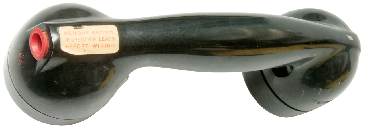
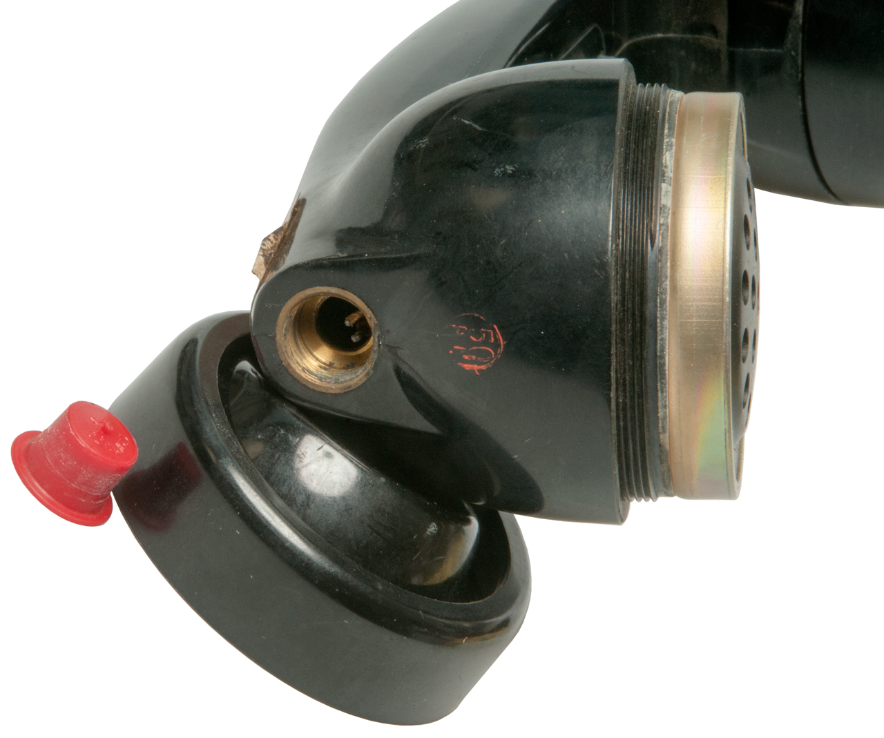
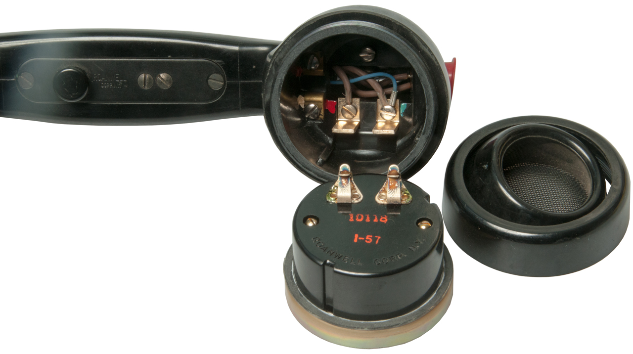
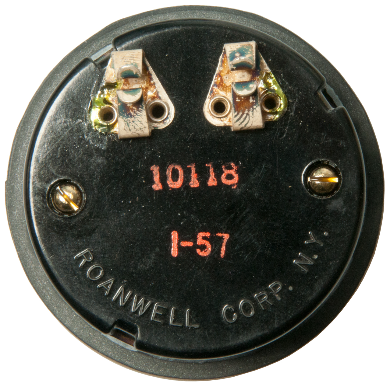
Roanwell 51007A
Photos
Fig 1
|
Fig 2
 |
Fig 3 Speaker 10088
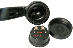 |
Fig 4
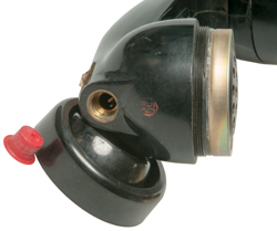 |
Fig 5 Mike element 10118 is from the
NT-51007A (MIL-HDBK-173)
 |
Fig 6
 |
Fig 7 Mike Element 10118: no polarity
marks.
The dynamic mike elements have (+) and (-) polarity
marks next to the electrical terminals.
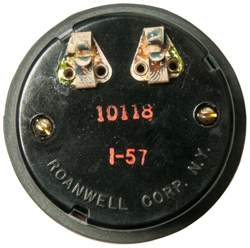 |
Fig 8 Carbon Mike Element marked:
Roanwell Corp. 13544 (A)
This has the look of a classic telephone carbon mike
element.
Measures about 1500 Ohms, not 35 Ohms,
so probably needs help or replacement.
|
|
Brush Development Co
|
2383832
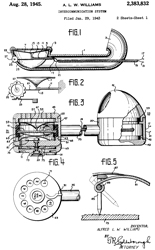
Intercommunication system, Alfred L
W Williams, Brush
Development Co, App: 1943-01-29, Pub:
1945-08-28, -
The microphone works by bending a piezo bar. The
call wheel works by bending this same bar. The
microphone also acts as the speaker by means of a
speaking tube that connects the mike and speaker
positions.
Brush Development Co made a lot of piezo crystal based
products.
|
Atwater Kent
Probably not sound powered, but early speakers.
Atwater
Kent was the assignee on almost 200 patents. Many
related to early automobile electrical parts, like the Unisparker.
Horns
for both radios and cars.
Atwater
Kent Manufacturing Co has about 85 patents.
|
1672493
Loud speaker, Russell
T Kingsford, Atwater
Kent Manufacturing Co, 1928-06-05, -
It looks like there's a wooden part to the horn and a
metal/plastic part. The driver seems to be made
from plastic or metal that has cracked.
The Freed-Eismann Radio
Speaker FE-50 speaker is made of wood and metal
and has lasted very well. The Dicotgraph driver
is metal and looks like new.
From the photos you can get an idea of how to make one
of these. Two sides of the horn are flat
surfaces. The other two sides with curves are
made up of a number of sticks that are glued together.
The Voice of The Theater
speaker may have been made by cutting slots into ply
wood then bending the wood on a form. But again
there are two sides of the horn that are flat
surfaces.
|
|
1673461
Loud speaker, Kent
Arthur Atwater, 1928-06-12, -The driver looks
like a standard headphone type speaker, not the sound
powered type.
|
|
1364381
Prismatic telescope, Kent
Arthur Atwater, App: 1919-02-01, Pub:
1921-01-04, -
Prismatic binoculars
(Wiki)
W.W. I 1914 - 1918, so this is between the two world
wars.
It's usual for one inventor to patent optical and
electrical items.
|
|
1960599
Mechanical rectifier, Albert
D Silva, ATWATER
KENT Manf, 1934-05-29, - a classic humming
automotive vibrator with additional contacts that
rectify the high voltage to provide DC output.
Car battery supplies the A filament voltage and the
vibrator supplies filtered B+.
|
Known for horn speakers and microphones. (Wiki)
SP13.5TRBXWK
Rearaxial Softspeaker data sheet (1 April?)
3095484
Unidirectional microphone, Wayne
A Beaverson, Robert
C Ramsey, Electro
Voice, 1963-06-25, - 642 Cardiline shotgun
microphone (EV
642 data sheet).
4071112
Horn loudspeaker, D.
Broadus Keele, Jr., Electro-Voice,
1978-01-31, - 1982
White Paper on Constant-Directivity Horns.pdf
Bell Labs
|
1707545
Acoustic device, Edward
C Wente, Bell
Labs, 1929-04-02, 181/159 - Horn
speaker/microphone |

|
1869178
Sound translating device, Albert
L Thuras, Bell
Labs, 1932-07-26, -
Note use of electrical circuit elements as analogs for
mechanical elements.
I have a book about the
correspondence between mechanical acoustics and
electrical equivalents. Not sure of title.
See Wiki: Thiele/Small
parameters -
|
|
1992268
Acoustic device, Edward
C Wente, Bell
Labs, 1935-02-26, 181/187 - sectional horn |
|
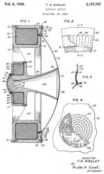
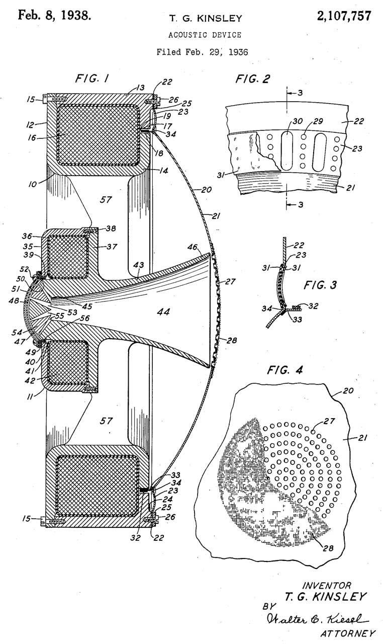
2107757
Acoustic device, Thomas
G Kinsley, Bell
Labs, 1938-02-08, - a horn speaker behind a
woofer with holes in the aluminum speaker dome shaped
cone. |
RCA model 103 speaker
|
1271527, 1271528, 1271529 see
Lektophone above
|
|
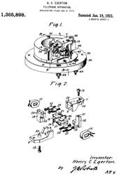
1365898
Telephone apparatus, Henry
C Egerton, Western
Electric, 1921-01-18, - loud speaking
telephone receivers
This is the sound powered efficient design.
|
|
1631646
Sound-reproducing apparatus, Chester
W Rice, General
Electric, 1927-06-07, - tweeter?
|
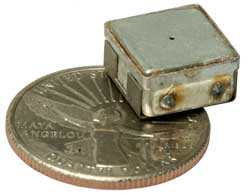
Shure
MC30 Microphone
Small Controlled Magnetic Microphones (MC11J/en-US: MC30_MC11J_guide_en-US.pdf)
Frequency Response: 400 to 4,000 Hz
Pattern: Omnidirectional
Case: Zinc plated annealed brass and Mu-metal (Wiki)
DC Resistance: 595 Ohms
Clicks when tested with 1 mA (Fluke 87V DMM Diode function)
Der DE-5000
LCR meter 1kHz: 226 mH and a Q of 1.187 - The TL-22
tweezers work will, do not block the hole and you can hear
the 1 kHz tone
Fig 1 MC30 on US Quarter coin.
The label is printed on the Mu metal
also see Shielding
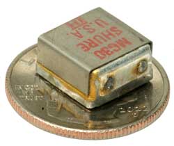
|
Fig 2
 |
Also see Spy Radios \ Technical Services
Division - scroll down to Small Microphones (Note
another source is hearing aids)
Testing Spy Mikes
This is a method Pete ( Spy Radios) came up
with to test the small microphones typically used in Cold
War spy applications.
|
- Establish some basic performance data on
several types of small mics that were (or could
have been) used for clandestine purposes.
Especially the Shure MC30 (a 'standard' item for
CIA in the late 50's and early 60's), the Brush
BA-110, and several types of hearing-aid
transducers.
- Do a 'qualitative' measurement of sensitivity
at 1 KHz.
- Do a measurement of the frequency response
curve, to see how the DUTs perform for voice-audio
purposes.
- Do NOT attempt to measure Directionality,
"hi-fi" performance, high SPL performance, or
other params.
Attached is a picture of my test setup.
The "speaker" in the picture is an old Shure R5
mic cartridge. It works, but it's not a very good
choice. Instead, I'm now using a modern
Chinese-made dynamic mic element "PS-D27", which
is much better.
For "calibrating" the test setup, my Reference
Mic is a Transound TSB-6022A (a 6mm
electret), which is known to have a very flat
response. Measurements of the Reference Mic are
used for comparison against each Test Mic.
The Test Mic is inserted into the smaller tube,
with a scrap of fabric stuffed behind it. The
small tube (3/4" OD : 1/2" ID=1/2" plastic pipe)
is then rolled up in a strip of fleece fabric,
then inserted into the larger tube (which contains
the "speaker") (2" OD : 1-1/2" ID=1-1/2" plastic
pipe). When assembled, the test mic is very close
to the "speaker". The purpose of
the enclosure is to avoid reflection effects,
and to have a close coupling that is much shorter
than the sound wavelength.
The "speaker" is driven by an HP-3310B function
generator, set for sine output, with an
amplitude in the 50-300mV range (typically).
The Test Mic is amplified through a Shure M68
mixer, and the output of the mixer is monitored by
a DVM (to measure AC volts RMS).
The "noise floor" on this setup is 5-10 mV,
while the signal is from 0 to several hundred mV.
Attached are a couple of spreadsheets of my
test data. Each spreadsheet shows the 'reference'
vs the tested mic (both are normalized to 1 KHz,
so the absolute amplitude can NOT be compared). It
is assumed that the 'reference' graph reflects the
non-perfect response of the test setup, so the
true response of the Test Mic can be extrapolated.
In these examples, there is the Shure MC30
(dynamic) ( MC30.xlsx) , the
BT-1751 (electret) ( 1751.xlsx), and 1588
(dynamic center-tapped 'receiver') ( 1588.xlsx).
Note that the 1588 is really pretty good as a
microphone for voice-audio.
Pete
|
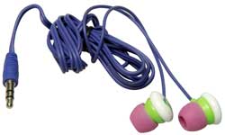
Cheap EarBuds
eBay title: "Lot of 5 In-Ear 3.5mm Simple Stereo
Earphone Earbuds Headset Head Phone" for $4.99 & free
shipping.
In the YouTube Understanding and
Building Crystal Radio Sets (Xtal1800 Ref 1) @14:04
it was mentioned "modern
dollar store earbuds, i.e. those with rare Earth
magnets are almost as good. An audio matching
transformer is needed."
When tested with the AMY6 Magnetic Polarity
Tester, both as is and after opening as in Fig 2
below, no magnetic filed is seen.
DE5000 LCR Meter Testing
Rs (DC): 31.94 Ohms
Ls: 55.5 uH @ 1kHz
I got a similar answer when testing the ear buds that came
with the Roku Ultra
where they plug into the remote.
Maybe are sensitive when a transformer is used?
Photos
Fig 1
|
Fig 2
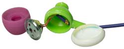 |
Knowles
Hearing Aid Speakers
Knowles
makes very small balanced armature speakers for use in
hearing aids. There are a lot of them on eBay ("Knowles
speaker").
Their drivers are used in some "in ear" speakers (eBay
"Knowles in ear") which are about $60 for a pair on eBay
by various makers.
Linsoul sells a large number of balanced armature ear buds
by many makers. Priced from $15 a pair to $1,500 a
pair.
ZS10 Pro
Located under Knowles because I think they use a couple
of Knowles ballanced armature drivers in each ear bud.
2023 Nov 21 on order eBay title:KZ
ZS10 Pro DIY Earbuds 5 Hybrid Driver 4BA+1DD in-Ear Monitor
Earphone A7U3Color: Black Without Microphone
These have two Balanced Armature drivers (high & mid
frequency) plus a 10mm dynamic driver
KZ
Acoustics - ZS10
Pro - lower price than eBay.
These sound better than the above cheap ($1 each) ear
buds and are much higher in quality.
Note that the ear bud connectors are marked "L" and
"R". You can see the "R" in Fig 3 below.
There is a stiff tube near the ear bud connector to
route the cable up and back. That means that there
is a Left and Right ear bud which can be identifier by
the connector toward the front top.
DE5000 LCR Meter Testing
Testing a single ear bud. Very loud 1 kHz tone.
Rdc = 24 Ohms
Ls = 94.1 uH @ 1 kHz.
Fig 1 Very nice packaging.
|
Fig 2 bag contains different sizes of
foam insert.
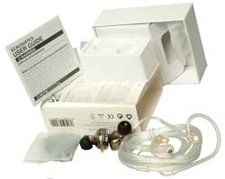 |
Fig 3
 |
I expect
that top of the line earbuds might be the B&O
Beoplay EQ $400 a pair. But these are
wireless so not good for Crystal Radios.
Summary
While noticeably better than the $1 ear buds they fall
far short of my computer speakers, which include a sub
woofer and far far short of my 7.1 Surround Sound Movie
system.
2912523
Electro-acoustic transducer, Knowles
Hugh S, Mullen
Joseph E, Industrial
Research Products Inc, Nov 10, 1959, 381/418, 335/301, 335/231, 335/252, 335/235, 310/25, 335/236 - for
use in hearing aids as both mike and speaker. Not
susceptible to or cause external magnetic fields so the
mike can be close to the speaker.
Collier Receiver
This was the receiver used by Marconi in 1901 for trans
Atlantic radio. See Crystal Radios Ref. 1.
|
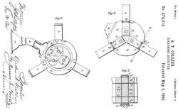 |
474214
Telephone Receiver, Arthur T. Collier, 1892-05-03, - |
Magnavox
What
Killed Consumer Electronics in America? What Happened to
Magnavox? General Electric Raytheon, 13:02 -
1448279
Electrodynamic receiver, Edwin
S Pridham, Peter
L Jensen, Magnavox
Co, 1923-03-13, -
National
Research Council of Canada
3112005
Earphones, Edgar
A G Shaw, George
J Thiessen, National
Research Council of Canada, 1963-11-26, - George has
other very impressive patent on a fog horn.
Measuring
This is an easy way to both measure the impedance of an
audio transducer. Note this is different from the DC
resistance measured with something like the Fluke 87V DMM.
There are a number of files at the above URL including:
Setup.exe, Brochure, Quick Start Guide v3, Quick Start Guide
v3.1, White Paper on speaker measurements and a couple of
reviews. They also have a comprehensive book store.
I have a book that goes into how the mechanical properties
of a transducer are tightly related to its electrical
equivalent circuit. Maybe in the Sonobuoy
Books paragraph.
This small box works with measurement software running on a
computer to make two terminal audio measurements and the
version 3 includes some sophisticated characterization of
audio drivers.
11272301
Measuring loudspeaker nonlinearity and asymmetry, Brian
K. Myers, John
L. Murphy, Parts
Express International, 2022-03-08, - cites
26 patents
Related
Audio - military audio
connectors
Audiopack
Sound Systems 360 Public Address Set -
Aviation Headsets -
Bell System 302 Dial Phone - the "I
Love Lucy" phone, this is the first phone I can
remember. The first phone to have all the parts in one
case.
Bell System 500 Dial Phone - basis
for the REN Ring Equivalence Number that's on the label of all
modern phones
Bell system 2500 Touch Tone phone -
Beltone 12D Audiometer
CA-67 Interface Unit, Automatic Data
Processing Stardynamic
5895-01-443-5081
Cell Phones
DialTelegraph
EE-8 Telephone Set
E-89-A Telephone Repeater
EM200 EM200 Ear Mike
Fullerphones
Gamewell
- Long Range Acoustic Devices -
GR650A General Radio GR 650-A &
GR 1650B Impedance Bridges
GRsound General Radio Sound
Measurement Instruments
GRA-39 Radio Set Remote over phone
wire
H161 H-161E/U Headset used in Crew
Served Vehicles (2 connectors)
H-207A/VRC Handset
H250 H-250/U Handset with Noise
Canceling mike
H251 H-251A/U Headset (earphones)
H33 H-33F/PT Handset
H350 H-350/U Handset
Harris RF-5980-SA001
Amplified Speaker
Harris TS1000 ADSL Test Set
-
Harris TSP-21 Telephone Test
Set Plus (like but set, but belt-clip & operators headset
Hearing -
hearing aids - ZenithA2A uses 2 tubes
Home Theater - 7.1 Surround
Sound - Voice Of The
Theater Speakers (very efficient)
HP204 HP 204B Audio Oscillator from
HP 3350 Carrier Test Set (AN/USM-181 Telephone Test Set
HP241A HP 241A Audio Oscillator
w/Radio Buttons
HP415E HP 415E SWR Meter - 1 kHz
tuned voltmeter
HP4260 HP 4260A Universal Bridge
HP 4261A LCR Meter
HP427A HP 427A Voltmeter AC &
DC Volts & Ohms
HP4274_4275_LCR lHP
4274A & HP 4275A LCR Meters
HP4332 HP 4332 LCR Meter
HP 4395A HP 4395A Combination
Network, Spectrum, Impedance Analyzer includes audio
frequencies
HP33120 15 MHz Function/Arbitrary
Waveform Generator
HS2B4 Plantronics Supra -01NC
992C Headset
HS30A HS-30-A Headphones, CD-604
Transformer
HYX-65-1 Wire-line Adapter Local
Unit & KY-65
KS-8455L2 Kick Test Set Line Loop
Tester Telephone Installers & Repairman's Meter
KY68 KY-68 Secure Field Telephone
LS-147 Intercom
LS454 LS-454/U Loudspeaker
LS-685/U Crystal Loudspeaker
LS-688 PM Loudspeaker
M1024 Magnacord 1024 Reel to Reel
Tape Recorder
M153 M-153/U Microphone, Voice
Silencer
M80 M-80/U Handset (Microphone)
MAA Military Audio Accessories -
tables with thumbnail photos & links to more info.
Magnetics
MATEL 2C800 Field Phone by Racal
Acoustics Ltd.
MK-356/G Wire Splicing Kit
MRC67 MRC-67A Amplifier-Speaker
Music
No6 - No. 6 Dry Cell
Noisecom 7110-FAC Programmable
Noise Generator
NSLB Model NS-LB Noise Generator
Orion
Electronics Ltd. Cellular Base Station ST616-CBS -
simulated cell tower for man-in-the-middle attack (Wiki)
Panasonic KX-TA824 Telephone
System
PatchP Audio Patch Panel
Racal MATEL 2C800 Field Phone
RS 38-A Carbon Microphone
RT1185 RT-1185/GRA-114 Sound
Observer Receiver Transmitter
SB-22A Analog Switchboard
SB-4170 Digital Switchboard
SB-3614A(V)/TT Telephone Switchboard
SG-886A/UR Interference (Noise &
Tone) Generator
SidekickTandN Tempo Sidekick
T&N Telephone Line Tester
Sonobuoy
Spying on Cell (Mobil)
Phones
Subscriber Loop
Analyzers
TA-1 Sound Powered Telephone Set
TA-1042 Digital Non-Secure
Voice Terminal (DNVT)
TA-312/PT Telephone Set (Field
Phone)
TA-341/TT
TA-838/TT Telephone Set
Teledyne Avionics TA-3D Acoustic
Impedance Meter - ear canal impedance
Telegraph Telegraph Equipment,
Stock Ticker, District Telegraph, Teletype, Keys, Relays,
Sounders, Veedre Counter, Early Connectors, Electro-magnets
Telephones
Telephone Patents & photos
Telephone Tool Kit
Telephone Poles - Utility,
Power, Cable TV Poles
Tempo Sidekick T&N Line
Tester
TF2700 Marconi TF-2700 Universal
Bridge
TG-5-B Telegraph Set
Tone & Probe
station wire testing
TS-2839/GY German H-33 Audio Test Set
TS-3647/G, Control Orderwire Unit
(COU), Telephone Test Set
TS585 TS-585 Audio Level Meter
TSD-3600 Telephone Security Device
TSEC/KY-68 Digital Subscriber Voice
Terminal
Tuning Forks
& Helmholtz Resonators
U229AA U-229 Audio Accessories
U229PO U-229 Pin Out by Function
U229Y "Y" Cable, U-229/U
Ultrasonics
UIQ10 UIQ-10 Public Address Set
VIC VIC Vehicle Inter Communication
& VRC-12
Series Radios
Voice Over Internet Protocol (VOIP) Phone
Service
Western Electric 202 Dial phone-
consists of a phone and a "sub set" that's mounted on the
wall.
WE 500 Dial Phone -
Western Electric 2554 Wall Touch
Tone Telephone
WTFME1 Funkanpaßgerät WT-FM-E1 AP01
Telefunken Military wire to radio interface
Xtal1800 Crystal Radio 1800?
& Brooke Clarke #1 & horn speaker
ZM-4B/U Resistance Bridge
Zo Transmission Line Zo (not a
constant) vs. Frequency - down to audio
References
History
of the AES: Loudspeaker
History -
IEEE:
Bell,
Watson, Soft Iron, and the Insight That Commercialized the
Magneto Telephone, Ralph O. Meyer, V108, No. 12 -
Crystal Radio Net - Sound Powered
Phones for Crystal Radios - Impedance
and Resistance Measurments Of Sound Powered Elements -
Submarine Telephone Talker's Manual, NAVPERS 16171 (subtalker.pdf),
Dec 1944, by NDRC & Navy training (then Restricted) -
Circuits (most common in sub movies is the "1MC"):
Circuit
|
Type
|
Function
|
Locations
|
XJA
|
Phone
|
General Communication
|
All compartments
|
JA
|
Phone
|
Torpedo-gyro control
|
Aft Torp, Maneuvering, Conning,
Control, For Torp
|
1JP
|
Phone
|
Exterior circuit
|
Bridge to XJA-or-JA; Conning to Deck
gun
|
7MC
|
Speaker |
Combat Information
|
Bridge, Conning & Control
|
1MC
|
Speaker |
Emergency & PA
|
all compartments
|
Numbers: WUN, TOO, THUR-REE, FO-WER, FI-YIV, SIX, SEVEN,
ATE, NINER, ZE-RO
Microphones
Explained for Beginners, August 1938 Radio-Craft -
Single Button Carbon, Double Button Carbon, Condenser,
Ribbon, Moving Coil, Diaphragm type Crystal, Sound Cell
Crystal
Horn
Loudspeaker Design, J. Dinsdale, Wireless World, March, May
& June 1974 -
YouTube: Bruce
Yeany: String
Telephones versus Sound tubes..., 9:23 - First string
based, the @ 5:18 tube
based (much better than string) - Whisper tube science
demonstration, 3:12 - Homemade speaker made
with a toy motor, 4:47 -
6175633
Radio communications apparatus with attenuating ear pieces
for high noise environments, Jeffrey C. Morrill, Gerald J.
Jonas, Cavcom,
2001-01-16, - cites
86, cited
by 63
Transmission and Reception of Sounds Under Combat
Conditions, OSRD, 1946 (declassified 1960), 318 pgs (transmissionrece03unit.pdf)
- includes drawings of rubber
speaker holders like used on helmets and earphones (Chapt 11
pg 192). Chapt 15 Hearing Aids pg 234,
Links
Microphone Parts - S12
Kit - Tested:
Where Does The Tone Come From In A Microphone?, 29:50 -
True
Condenser Build, 18:49 -
PRC68, Alphanumeric
Index of Web pages, Contact,
Products for Sale
Page Created 2017 October 13


James Wilkes: